
The production topology contains redundant components and is used for all mission-critical and end-user network traffic.
The figure below shows a validated production topology for this example:
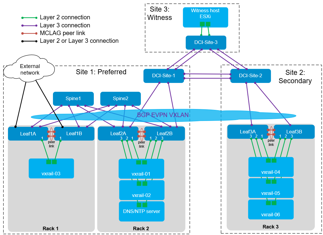
vSAN stretched clusters require three fault domains: preferred, secondary, and witness (also referred to as Sites 1, 2, and 3).
All leaf and spine switches in the stretched cluster topology must be running Dell Enterprise SONiC. Data center interconnect (DCI) switches and external network switches can run SONiC or another network operating system. Switch requirements are detailed later in this document.
Each rack contains two leaf switches for redundancy and performance. A multichassis link aggregation group (MC-LAG) peer link connects each pair of leaf switches. When spines are used at a site, every leaf switch is connected to every spine switch to form a leaf-spine topology.
This example uses a leaf-spine fabric in Site 1 and a single leaf pair in Site 2 to demonstrate the connection methods for leaf-spine compared to leaf-only topologies. Spines can be used at one or both sites as needed. At a minimum, one leaf pair is required in each of the preferred and secondary sites. Spines are required if more than one leaf pair is used in a site.
BGP EVPN with Virtual Extensible LAN (VXLAN) stretches virtual (overlay) Layer 2 networks across a physical (underlay) Layer 3 leaf-spine fabric. To facilitate this, each leaf pair is configured as a VXLAN tunnel end point (VTEP). In this topology, the Layer 2 networks are stretched across the spines in Site 1 and across the Site 1 and Site 2 DCI switches in the same manner. This BGP EVPN architecture allows for the scalability of Layer 3 networks with the mobility benefits of a Layer 2 network. For example, a VM or physical host can be moved from one rack - or site - to another, without needing to change its IP address and gateway information.
In Figure 1 above, Leaf 1A and Leaf 1B are also connected to an external network, which is typically an existing network in the data center with DNS services, NTP services, and Internet access. Any leaf pair can be used, and these connections are optional. Leaf 3A and Leaf 3B can also be connected to an external network in Site 2 in the same manner (not shown).
Leafs 2A and 2B in Site 1 and Leafs 3A and 3B in Site 2 connect to their respective DCI switch. They are each BGP peers with the DCI switch they are directly connected to. The links between the leafs and DCI switches must be Layer 3 to support BGP. Leafs 2A and 2B are also configured as BGP EVPN peers with Leafs 3A and 3B. This enables Layer 2 networks to be stretched between sites. While the DCI switches are configured for BGP, they are not configured for EVPN or VXLAN.
Leaf switches with uplinks to an external network or to DCI switches are called border leafs. In figure 1, all three leaf pairs are acting as border leafs in addition to supporting the VxRail nodes connected to them. As an option, you can add a dedicated pair of border leafs with no VxRail nodes connected. This could be preferable if the VxRail node leaf switches are heavily used or there are large amounts of North-South traffic. If dedicated border leafs are used, these leafs must be connected to the spine switches in the same manner as the other leafs.
VxRail nodes in the VxRail vSAN stretched cluster are in Sites 1 and 2. The nodes in this example are named vxrail-01 through vxrail-06. Dell Technologies recommends using an equal number of VxRail nodes in Sites 1 and 2, which provides equal resources at both sites if there is a complete outage at either site. A witness host running ESXi must be deployed in Site 3 as required for a stretched cluster.