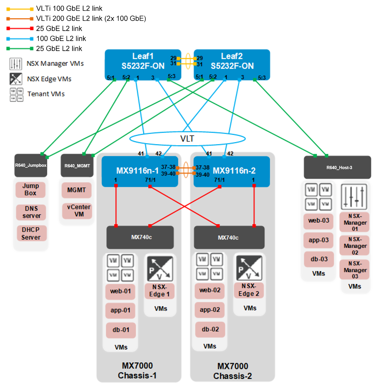
The diagrams shown below depict the logical and physical topologies for the deployment examples used in this guide.
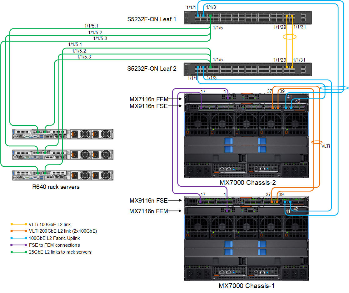
Two Dell EMC PowerEdge MX7000 chassis are set in a multichassis management group. The Dell EMC Networking MX7116n FEMs are connected to the Dell EMC Networking MX9116n FSEs. The MX9116n FSEs are in a VLTi connected on QSFP28-DD ports 1/1/37 and 1/1/39. The uplinks from both MX9116n FSEs are connected to both Dell EMC PowerSwitch S5232F-ON leafs using ports 1/1/41 and 1/1/42.
The Dell EMC PowerSwitch S5232F-ON switches are connected in a VLTi that uses ports 1/1/29 and 1/1/31. Port group breakout is configured on the100 GbE port 1/1/5 to create 4x 25 GbE ports. Each S5232F-ON switch is then connected to the three PowerEdge R640 servers using the 1/1/5:1, 1/1/5:2, and 1/1/5:3, 25 GbE ports.
The following wiring diagram shows the physical layout used to validate the deployment examples provided in this guide.