
Uplinks to the existing network may be configured as L2, L3 routed, or L3 VLAN. This section covers L2 uplinks.
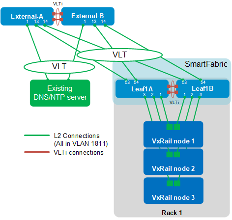
The switches are cabled as shown in Figure 19. When L2 uplink configuration is complete, Leaf1A and Leaf1B will connect with a VLT port channel to a switch pair named External-A and External-B. In this example, an existing DNS/NTP server also connects to the external switches using a VLT port channel. All VLT port channels use LACP in this guide.
All ports on the four switches shown in Figure 19 are in the External Management VLAN, 1811.
Configure L2 uplinks in SFS
L2 uplinks to the external network are configured as follows:
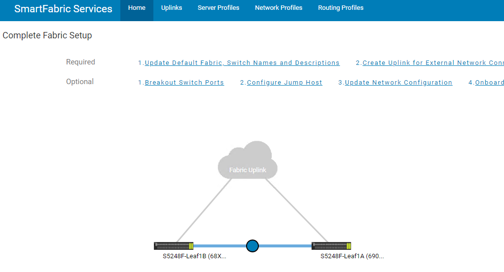
- On the SFS UI home page, click 2. Create Uplink for External Network Connectivity.
- On the Uplink Details page, select Layer 2. Enter a Name and optionally a Description.
Figure 20. Uplink details 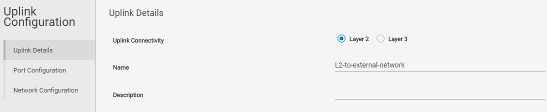
- Click NEXT.
- On the Port Configuration page, select the uplink ports used on each leaf switch and set the LAG Mode to LACP or Static. In this example, 100 GbE ports 1/1/53-1/1/54 are used on each switch, and the LAG mode is set to LACP.
Note: Be sure to configure the corresponding ports on the external switches with the same LAG mode. External switch configuration examples using LACP are provided in the Configure external switches for L2 connections section of this guide.
Figure 21. Uplink port configuration 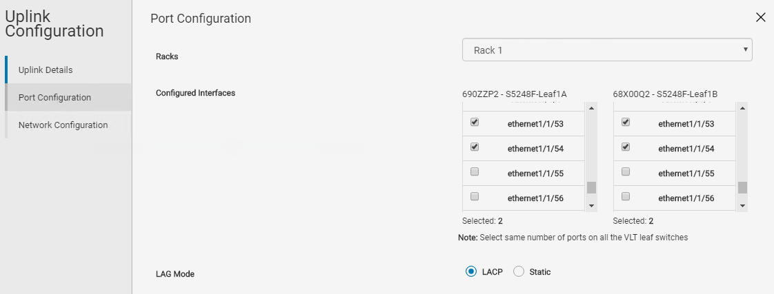
- Click NEXT.
- VxRail Manager must be able to contact a DNS server to resolve hostnames during deployment. The External Management VLAN is created to enable this, and the uplinks are added to it as follows: On the Network Configuration page, click ADD NETWORK.
Figure 22. Network configuration page 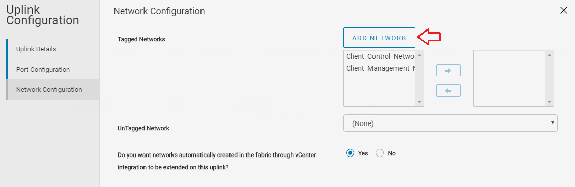
- In the dialog box that opens, provide a Name, Description (optional), and a VLAN ID for the External Management network. In this example, VLAN ID 1811 from Table 3 is used.
Figure 23. Network details 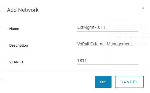
- Click OK.
- Next to Tagged Networks, select the External Management VLAN created above, ExtMgmt-1811. Use the arrow button to move it to the box on the right, as outlined in red in Figure 24. This makes the uplinks tagged members of the External Management VLAN.
Figure 24. Uplink ports tagged in the External Management Network 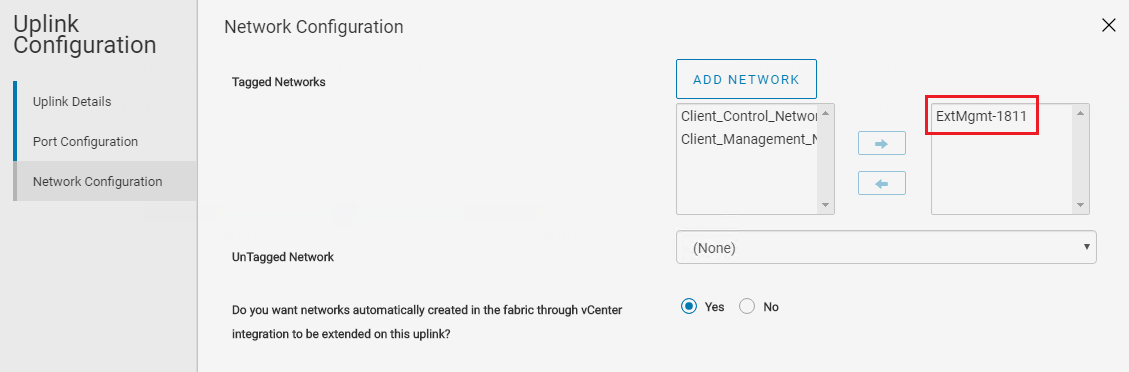
- Leave the box next to UnTagged Network set to None.
- If networks automatically created through vCenter integration are to be extended on this uplink, select Yes. Otherwise, select No. Yes is used in this example.
Note: Networks created through vCenter integration include the External Management, VSAN, vMotion, and VM Networks created during VxRail deployment. It also includes networks added through OMNI post-deployment.
- Click FINISH to apply the settings.
After uplink configuration, the SFS UI Home page appears, as shown in Figure 25.
Optionally, enter the show smartfabric uplinks command at the leaf switch CLI to view configured interfaces and networks on the uplink.
S5248F-Leaf1A# show smartfabric uplinks
----------------------------------------------------------
Name                  : L2-to-external-network
Description           :
ID                    : 8ca32653-854c-4347-af94-e6afaa136c3a
Media Type            : ETHERNET
Native Vlan           : 0
Untagged-network      :
Networks              : network-1811
Configured-Interfaces : D86ZZP2:ethernet1/1/54, D86ZZP2:ethernet1/1/53, 76K00Q2:ethernet1/1/54, 76K00Q2:ethernet1/1/53
Configure external switches for L2 connections
This section shows example configurations for both external switches for L2 connections to the SmartFabric.
General settings
Configure the hostname, OOB management IP address, and OOB management route as shown.
| External-A | External-B |
|
|
Configure VLANs
Create the External Management VLAN. If traffic will be routed from the external switches to other external networks, assign a unique IP address on each switch and configure VRRP to provide gateway redundancy. Set the VRRP priority. The switch with the highest priority value becomes the master VRRP router. Assign the same virtual address to both switches.
| External-A | External-B |
|
|
Configure interfaces
Configure the interfaces for connections to the SFS leaf switches. Interfaces 1/1/13 and 1/1/14 are configured in VLT port channel 100 in this example. Port-channel 100 is set as an LACP port channel with the channel-group 100 mode active command.
Use the switchport mode trunk command to enable the port channel to carry traffic for multiple VLANs. Configure the port channel as tagged on VLAN 1811 (the External Management VLAN).
Optionally, allow the forwarding of jumbo frames with the MTU 9216 command.
In this example, interface 1/1/1 on each external switch is configured in VLT port channel 1 for connections to the DNS/NTP server. Port-channel 1 is set as an LACP port channel with the channel-group 1 mode active command.
Configure ports directly connected to nodes, servers, or other endpoints as STP edge ports. As a best practice, flow control settings remain at their factory defaults as shown.
| External-A | External-B |
|
|
Configure VLT
This example uses interfaces 1/1/11 and 1/1/12 for the VLTi. Remove each interface from L2 mode with the no switchport command.
Create the VLT domain. The backup destination is the OOB management IP address of the VLT peer switch. Configure the interfaces used as the VLTi with the discovery-interface command.
As a best practice, use the vlt-mac command to manually configure the same VLT MAC address on both the VLT peer switches. This improves VLT convergence time when a switch is reloaded.
If you do not configure a VLT MAC address, the MAC address of the primary peer is used as the VLT MAC address on both switches.
When the configuration is complete, exit configuration mode and save the configuration with the end and write memory commands.
| External-A | External-B |
|
|
Validation
Once the uplink interfaces have been configured on the external switches and in the SFS UI, additional validation is done using the switch CLI.
Show command output on External-A
Run the show vlan command to verify ports are correctly assigned to the External Management VLAN. Port channel 100 connects to the SFS leaf switches and is a tagged member of the same VLAN configured on the SmartFabric uplinks (VLAN 1811). It is tagged because it is also tagged on the SmartFabric leaf switches. The DNS/NTP server is connected on port channel 1, which is an access member of VLAN 1811 in this example.
External-A# show vlan
Codes: * - Default VLAN, M - Management VLAN, R - Remote Port Mirroring VLANs,
       @ – Attached to Virtual Network, P - Primary, C - Community, I - Isolated
Q: A - Access (Untagged), T - Tagged
    NUM    Status    Description      Q Ports
*   1      Active                     A Eth1/1/2-1/1/10,1/1/15
                                      A Po100,1000
    1811   Active    External_Mgmt    T Po100,1000
                                      A Po1
    4094   Active                     T Po1000
The show port channel summary command confirms port channel 100 connected to the leaf switches is up and active. Port channel 1000 is the VLTi, and port channel 1 is connected to the DNS/NTP server.
External-A# show port-channel summary
Flags:  D - Down    I - member up but inactive    P - member up and active
        U - Up (port-channel)    F - Fallback Activated
--------------------------------------------------------------------------------
Group Port-Channel           Type     Protocol  Member Ports
--------------------------------------------------------------------------------
1    port-channel1    (U)     Eth      DYNAMIC   1/1/1(P)
100  port-channel100  (U)     Eth      DYNAMIC   1/1/13(P) 1/1/14(P)
1000 port-channel1000 (U)     Eth      STATIC    1/1/11(P) 1/1/12(P)
Show command output on Leaf1A
With SFS, port channel numbers are automatically assigned as they are created. Port channel 1 is the uplink connected to the external switches and is up and active. Port channel 1000 is reserved for the VLTi.
Leaf1A# show port-channel summary

Flags:  D - Down    I - member up but inactive    P - member up and active
        U - Up (port-channel)    F - Fallback Activated
--------------------------------------------------------------------------------
Group Port-Channel           Type     Protocol  Member Ports
--------------------------------------------------------------------------------
1    port-channel1    (U)     Eth      DYNAMIC   1/1/53(P) 1/1/54(P)
1000 port-channel1000 (U)     Eth      STATIC    1/1/49(P) 1/1/50(P) 1/1/51(P) 1/1/52(P)
The L2 uplink, port channel 1 in this example, is added as a tagged member of VLAN 1811. This is verified at the CLI using the show virtual-network command as follows:
Leaf1A# show virtual-network
Codes: DP - MAC-learn Dataplane, CP - MAC-learn Controlplane, UUD - Unknown-Unicast-Drop
Un-tagged VLAN: 4080
Virtual Network: 1811
   VLTi-VLAN: 1811
   Members:
      VLAN 1811: port-channel1, port-channel1000
   VxLAN Virtual Network Identifier: 1811
      Source Interface: loopback2(172.30.0.0)
      Remote-VTEPs (flood-list):

Virtual Network: 3939
   Description: In-band SmartFabric Services discovery network
   VLTi-VLAN: 3939
   Members:
      VLAN 3939: port-channel1000, ethernet1/1/1, ethernet1/1/2, ethernet1/1/3
   VxLAN Virtual Network Identifier: 3939
      Source Interface: loopback2(172.30.0.0)
      Remote-VTEPs (flood-list):

Virtual Network: 4091
   Description: Default untagged network for client onboarding
   VLTi-VLAN: 4091
   Members:
      Untagged: ethernet1/1/1, ethernet1/1/2, ethernet1/1/3
      VLAN 4091: port-channel1000
   VxLAN Virtual Network Identifier: 4091
      Source Interface: loopback2(172.30.0.0)
      Remote-VTEPs (flood-list):