
Compute server connectivity
Compute server connectivity
-
Compute server connectivity
Cisco UCS B-Series blade servers and Cisco UCS C-Series rack servers contain at least one physical Cisco UCS virtual interface card (VIC) for server connectivity.
The VIC passes converged FC and IP network traffic through the Cisco UCS 5108 blade server chassis midplane to the FEX.
The Cisco UCS C-Series rack servers can connect directly to each FI.
Cisco UCS B-Series blade server connectivity
Cisco UCS B-Series blade servers contain half-width blades with 4th-generation Cisco UCS VICs on supported servers. Half-width M6 servers can contain a 4th-generation Cisco UCS VIC 1440 in the motherboard (mLOM) mezzanine slot. The Cisco UCS VIC 1440 are installable with a port expander card for native 40 Gbps connectivity to each fabric.
The following table shows the UCS B-Series network connectivity:
Table 5. Cisco UCS B-Series network connectivity
Blade type
Cisco UCS VIC combination
Bandwidth to each FEX
Total available bandwidth
Half-width
1440
20 Gbps
40 Gbps
1440 + port expander
40 Gbps
80 Gbps
1440 + 1480*
60 Gbps
120 Gbps
1440 + port expander + 1480
80 Gbps
160 Gbps
15411
20 Gbps
40 Gbps
15411 + port expander
40 Gbps
80 Gbps
*Dell Technologies does not recommend using a 1440 + 1480 combination without a port expander to avoid causing unbalanced workloads. When pairing the two VICs, use a port expander on the 1440 VIC to balance the workload per fabric appropriately.
The following figure shows an eight-link l/O module (IOM) at 25 Gbps port speed on a Cisco UCS blade server chassis with FEX to FI connections:
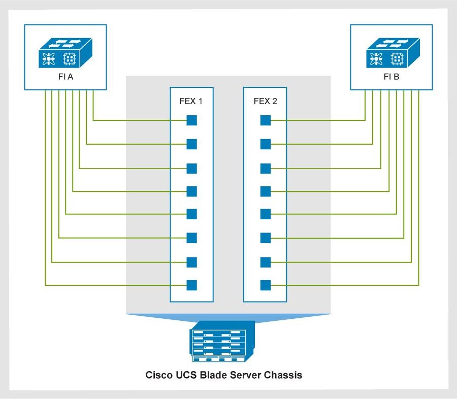
Figure 1. FEX to FI connections on a Cisco UCS blade server chassis
Cisco UCS Manager 4.1 (2a) or later allows the configuration of Cisco UCS 2408 FEX (IOM) with Cisco UCS VIC 1440 adapters and port expanders. This configuration supports up to 40 Gbps aggregate flow and 25 Gbps single flow per virtual Network Interace Card (vNIC).
Cisco UCS C-Series rack server connectivity
Cisco UCS C-Series rack servers connect directly to the FIs. The Direct Connect mode allows single-cable management and data traffic for these servers by the Cisco UCS Manager. Each Cisco UCS VIC connects to the FI using a single link. This approach is preferred for configurations with fewer servers.
A single server does not support different generations of VICs. Use either the Cisco UCS VIC 15xxx or 14xx series.
In Direct Connect mode, 4th-generation Cisco UCS C-Series rack servers include the following features:
- Cisco UCS VIC 1467, a Small Form-Factor Pluggable (SFP28) mLOM card for the M6 servers.
The card supports 10/25-Gbps Ethernet or FCoE.Cisco UCS VIC 1477, a dual-port Quad Small Form-Factor (QSFP28) mLOM card for the M6 servers, and 40-Gbps or 100-Gbps Ethernet or FCoE.
- Cisco UCS VIC 15428, a Small Form-Factor Pluggable (SFP28) mLOM card for the M6 servers.
The card supports 10, 25, or 50-Gbps Ethernet or FCoE.
- Cisco UCS VIC 15238, a Small Form-Factor Pluggable (SFP28) mLOM card for the M6 servers.
The card supports 40, 100, 200-Gbps Ethernet or FCoE.
Cisco UCS C-Series rack server direct connect license
The following table shows the port-to-FI connections of the Cisco UCS VICs:
Table 6. Cisco UCS C-Series VIC connections
Connectivity type
Connections
Single-link connectivity 1477/1495/15238
Port 1 connects to FI A.
Port 2 connects to FI B.
Dual-link connectivity 1455, 1467, 15428
Ports 1 and 2 connect to FI A.
Ports 3 and 4 connect to FI B.
Cisco UCS mixed server configuration
The Cisco UCS architecture uniquely combines compute, data network, and storage network access into a unified set of components that is managed through a single interface.
Cisco UCS integrates access layer networking and servers. Its unified fabric, supported by hardware and software components, runs diverse data center traffic over one converged network adapter. The elimination of switching in a Cisco UCS 5108 blade server chassis reduces network access-layer fragmentation, cutting down the number of switches, cables, adapters, and management points by up to two-thirds. All devices in a Cisco UCS domain are managed under a single domain, which remains highly available by using redundant components.
The following figure shows a mixed server configuration with Cisco UCS B-Series blade servers and Cisco UCS C-Series rack servers:
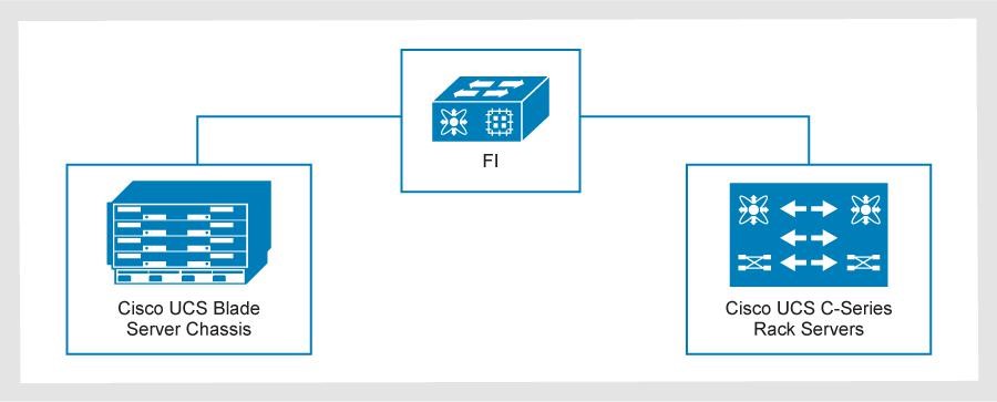
Figure 2. Mixed server configuration: Cisco UCS B-Series blade servers and Cisco UCS C-Series rack servers
FI oversubscription
For best performance, maintain an oversubscription rate of 8:1 or lower across all compute domains. In this ratio, ‘8’ denotes the committed host bandwidth, while ‘1’ denotes the Ethernet and FC uplinks.
The following table shows a 5108 chassis with 4-link and 8-link 25 G connections to the FI. A 6454 FI can have two, four, or six uplink options to a 9336C ToR switch. Oversubscribed areas are marked in red. As an example, 11 chassis with 8-links per side provide 2,200 GB of bandwidth to the FI per side, while two uplinks to the ToR provide only 200 GB of bandwidth. This results in an oversubscription of 2,200 ÷ 200 = 11. To avoid oversubscription, provide four uplinks from the 6454 FI to the 9336C ToR switch.
Table 7. 5108 chassis with 4-link and 8-link 25 G connections to the FI (example)
Cisco B-Series
Qty
Total bandwidth used per side
Oversubscription rates per side on the 6454 FI (8:1 ratio)
1 domain
2-uplinks (200 GB)
4-uplinks (400 GB)
6-uplinks (600 GB)
Chassis IOM with 4-Links 25 G
20 chassis (80 servers)
2 TB
10:1
5:1
3.3:1
Chassis IOM with 8-Links 25 G
11 chassis (88servers)
2.2 TB
11:1
5.5:1
3.6:1
Chassis IOM with 8-Links 25 G
10 chassis (80 servers)
2 TB
10:1
5:1
3.3:1
When planning your CI environment, follow the guidance in the previous table to avoid oversubscribing on Ethernet or FC connections.
Cisco UCS with NVMe over Fibre Channel
Starting with the Cisco UCS firmware release 4.2, NVMe over Fibre Channel is supported by the Cisco UCS Manager (FC-NVMe).
Version 4.2 of Cisco UCS Manager supports FC-NVMe on the following FIs:
- UCS 6454
- UCS 64108
3-Tier Platform support for FC-NVMe requires:
- Cisco UCS VIC 14xx series adapters on M5 and M6 blade and rack mount servers
- VMware vSphere ESXi release versions 7.0 or later
Disjoint Layer 2 configuration
In a Disjoint Layer 2 configuration, traffic is split between two or more networks at the FI to support two or more discrete Ethernet clouds. Configure Disjoint Layer 2 on the FI on ports that are not used for the standard LAN uplink traffic.
On the 4th-generation Cisco UCS 6454 or 64108 FIs, the network ports are:
- Non-FC 10 Gbps or 25 Gbps unified ports
- 40 Gb or 100 GbE Uplink ports
Upstream Disjoint Layer 2 networks give access to the cloud to servers or VMs in the same Cisco UCS domain.
The following figure shows an example of Disjoint Layer 2 networking into a Cisco UCS domain.
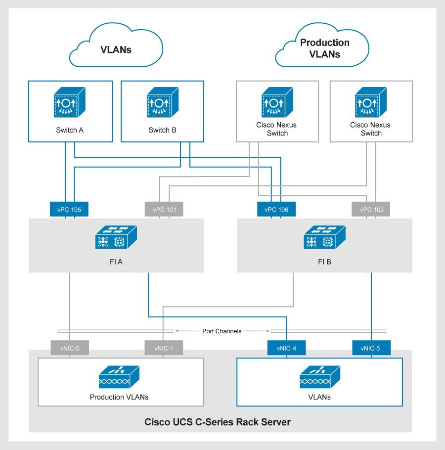
Figure 3. Disjoint Layer 2 networking into a Cisco UCS domain
- vPCs 101 and 102 are production uplinks that connect to the network layer of the 3-Tier Platform.
- vPCs 105 and 106 are external uplinks that connect to other switches.
You can also configure Disjoint Layer 2 network connectivity with an individual uplink on each FI.
Supported cabling in a UCSM domain
The following tables show the supported cabling:
Table 8. Supported cabling on a Cisco UCS 6454 FI
Source equipment
Destination
Connection type
SFP/cable type
Ports
Cisco UCS 6454 FI
Cisco Nexus 9336C
Ethernet uplink
100G AOC cables (domains 1 and 2)
QSFP-40G/100G-SRBD or QSFP-100G-SR4-S (domains 3 to 7)
49 to 54
Cisco UCS 6454 FI
Cisco MDS 9148T, 9396T, 9706-v2, and 9710-v2
FC uplink
DS-SFP-FC32G-SW with LC-LC FC cable
1 to 16
Cisco UCS 6454 FI
Cisco UCS 5108 chassis w/ B200 M6 blade servers
Cisco C220 and C240 M6 rackmount servers
Server
10/25G Twinax
(SFP-H10GB-CUxM)(SFP-H25G-CUxM)
FP-25G-SR-S with LC-LC FC cable
SFP-10G-SR-S with LC-LC FC cable
Note: 10G is only supported on chassis connections. All rackmount connections use 25G options.
Note: The “x” in SFP-H25G-CUxM and SFP-H10G-CUxM denotes the length of the cable.
5 to 48, 9 to 48, or 17 to 48 depending on how many FC uplinks are used.
Table 9. Supported cabling on a Cisco UCS 64108 FIs
Source equipment
Destination
Connection type
SFP/cable type
Ports
Cisco UCS 64108 FI
Cisco Nexus 9336C
Ethernet uplink
100G AOC cables (domains 1 and 2)
QSFP-40G/100G-SRBD or QSFP-100G-SR4-S (domains 3 to 7)
97 to 108
Cisco UCS 64108 FI
Cisco MDS 9148T, 9396T, 9706-v2 and 9710-v2
FC uplink
DS-SFP-FC32G-SW with LC-LC FC cable
1 to 16
Cisco UCS 64108 FI
Cisco UCS 5108 chassis w/ B200 M6 blade servers
Cisco C220 and C240 M6 rackmount servers
Server
25G Twinax (SFP-H25G-CUxM)
SFP-25G-SR-S with LC-LC FC cableNote: The “x” in SFP-H25G- CUxM and SFP-H10G-CUxM denotes the length of the cable.
9 to 96 or 17 to 96 depending on how many FC uplinks are used.
For more information about the supported cabling on a specific Cisco FI, see the corresponding data sheet: