


OneFS NANON

In OneFS parlance, PowerScale clusters with partial front-end connectivity are known as NANON clusters, the acronym abbreviating ‘Not All Nodes On Network’. Today, every PowerScale node in the portfolio includes both front-end and back-end network interfaces. Both of a node’s redundant backend network ports, either Ethernet or InfiniBand, must be active and connected to the supplied cluster switches at all times, because these form a distributed systems bus and handle all the intra-cluster communication. However, while the typical cluster topology has all nodes connected to all the frontend client network(s), this is not always possible or even desirable. In certain scenarios, there are distinct benefits to not connecting all the nodes to the front-end network.
But first, some background. For example, imagine an active archive workload. The I/O and capacity requirements of the workload’s active component can be satisfied by an all-flash F710 pool. By contrast, the inactive archive data is housed on a pool of capacity-optimized A3000 nodes for archiving inactive data. In this case, not connecting the A3000 archive nodes to the front-end network saves on the cost of the cables, ports, and simplifies the overall configuration, while also increasing security.
Such NANON cluster configurations are increasing in popularity, as customers elect not to connect the archive nodes in larger clusters to save cost and complexity, reduce load on capacity optimized platforms, as well as creating physically secure and air-gapped solutions. The recent introduction of the PowerScale P100 and B100 accelerator nodes also increases a cluster’s front end connectivity flexibility.
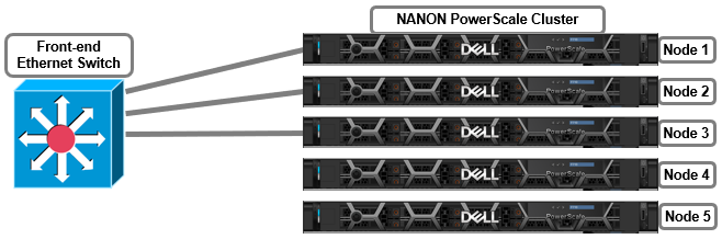
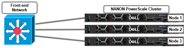
This NANON configuration is among the simplest of the partially connected cluster architectures. In this example, the deployment consists of five PowerScale nodes with only three of them connected to the network. The network is assumed to have full access to all necessary infrastructure services and client access.
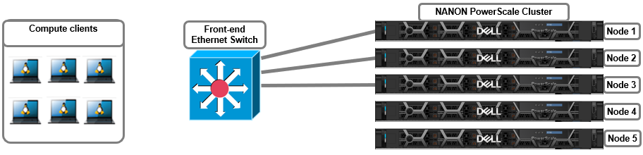
More complex topologies can often include separating client and management networks, dedicated replication networks, multi-tenant and other separated front-end solutions, and often fall into the NANOAN, or Not All Nodes On All Networks, category. For example:
The management network can be assigned to Subnet0 on the cluster nodes, with a gateway priority of 10 (that is, the default gateway), and the client network using Subnet1 with a gateway priority of 20. This would route all outbound traffic through the management network. Static routes, or source-based routing (SBR) can be configured to direct traffic to the appropriate gateway if issues arise with client traffic routing through the management network.
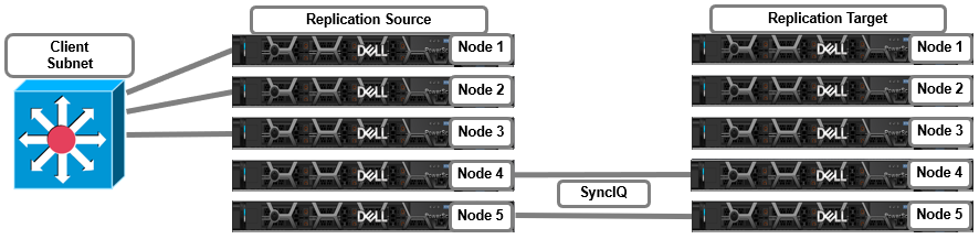
In the following replication topology, nodes 1 through 3 on the source cluster are used for client connectivity, while nodes 4 and 5 on both the source and target clusters are dedicated for SyncIQ replication traffic.
Other more complex examples, such multi-tenant cluster topologies, can be deployed to support workloads requiring connectivity to multiple physical networks.
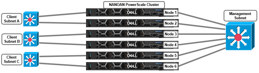
This topology can be configured with a management Groupnet0 containing Subnet0, and additional Groupnets, each with a subnet, for the client networks. For example:
# isi network groupnets list
ID         DNS Cache Enabled  DNS Search      DNS Servers   Subnets
--------------------------------------------------------------------
Client1    1                  c1.isilon.com   10.231.253.14 subnet1
Client2    1                  c2.isilon.com   10.231.254.14 subnet2
Client3    1                  c3.isilon.com   10.231.255.14 subnet3
Management 1                   mgt.isilon.com  10.231.252.14 subnet0
--------------------------------------------------------------------
Total: 4
Or from the WebUI by selecting Cluster management > Network configuration > External network.
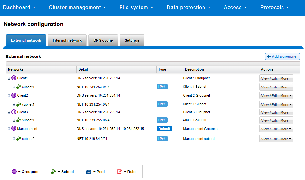
The connectivity details of a particular subnet and pool can be queried with the isi network pools status groupnet.subnet.pool CLI command, and will provide details of node connectivity, as well as protocol health and general node state. For example, querying the management groupnet Management.Subnet0.Pool0 for the six node cluster above, we see that nodes 1-4 are externally connected, whereas nodes 5 and 6 are not:
# isi network pools status Management.subnet0.pool0
Pool ID: Management.subnet0.subnet0

SmartConnect DNS Overview:
       Resolvable: 4/6 nodes resolvable
Needing Attention: 2/6 nodes need attention
        SC Subnet: Management.subnet0

Nodes Needing Attention:
              LNN: 5
SC DNS Resolvable: False
       Node State: Up
        IP Status: Doesn't have any usable IPs
 Interface Status: 0/1 interfaces usable
Protocols Running: True
        Suspended: False
--------------------------------------------------------------------------------
              LNN: 6
SC DNS Resolvable: False
       Node State: Up
        IP Status: Doesn't have any usable IPs
 Interface Status: 0/1 interfaces usable
Protocols Running: True
        Suspended: False
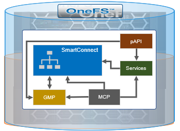
There are two core OneFS components that have been enhanced in 9.4 and later to better support NANON configurations on a cluster. These are:
Name | Component | Description |
Group Management | GMP_SERVICE_ EXT_CONNECTIVE | Allows GMP (Group Management Protocol) to report the cluster nodes’ external connectivity status. |
MCP process | isi_mcp | Monitors for any GMP changes and, when detected, will try to start or stop the affected service(s) under its control. |
SmartConnect | isi_smartconnect_d | Cluster’s network configuration and connection management service. If the SmartConnect daemon decides a node is NANON, OneFS will log the cluster’s status with GMP. |
Here’s the basic architecture and interrelation of the services.
The GMP external connectivity status is available using the sysctl efs.gmp.group CLI command output.
For example, take a three node cluster with all nodes’ front-end interfaces connected:
GMP confirms that all three nodes are available, as indicated by the new external_connectivity field:
# sysctl efs.gmp.group
efs.gmp.group: <79c9d1> (3) :{ 1-3:0-5, all_enabled_protocols: 1-3, isi_cbind_d: 1-3, lsass: 1-3, external_connectivity: 1-3 }
This new external connectivity status is also incorporated into a new Ext column in the isi status CLI command output, as indicated by a ‘C’ for connected or an ‘N’ for not connected. For example:
# isi status -q
                   Health Ext  Throughput (bps)  HDD Storage      SSD Storage
ID |IP Address     |DASR |C/N|  In   Out   Total| Used / Size     |Used / Size
---+---------------+-----+---+-----+-----+-----+-----------------+-----------
  1|10.219.64.11   | OK  | C |25.9M| 2.1M|28.0M|(10.2T/23.2T(44%)|
  2|10.219.64.12   | OK  | C | 840K| 123M| 124M|(10.2T/23.2T(44%)|
  3|10.219.64.13   | OK  | C | 225M| 466M| 691M|(10.2T/23.2T(44%)|
---+---------------+-----+---+-----+-----+-----+-----------------+-----------
Cluster Totals:              |  n/a|  n/a|  n/a|30.6T/69.6T( 37%)|
     Health Fields: D = Down, A = Attention, S = Smartfailed, R = Read-Only
           External Network Fields: C = Connected, N = Not Connected
Take the following three node NANON cluster:
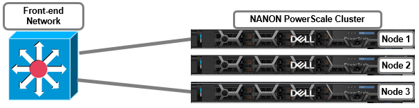
GMP confirms that only nodes 1 and 3 are connected to the front-end network. Similarly, the absence of node 2 from the command output infers that this node has no external connectivity:
# sysctl efs.gmp.group
efs.gmp.group: <79c9d1> (3) :{ 1-3:0-5, all_enabled_protocols: 1,3, isi_cbind_d: 1,3, lsass: 1,3, external_connectivity: 1,3 }
Similarly, the isi status CLI output reports that node 2 is not connected, denoted by an ‘N’, in the ‘Ext’ column:
# isi status -q
                   Health Ext  Throughput (bps)  HDD Storage      SSD Storage
ID |IP Address     |DASR |C/N|  In   Out   Total| Used / Size     |Used / Size
---+---------------+-----+---+-----+------+-----+-----------------+-----------
  1|10.219.64.11   | OK  | C | 9.9M| 12.1M|22.0M|(10.2T/23.2T(44%)|
  2|10.219.64.12   | OK  | N |    0|     0|    0|(10.2T/23.2T(44%)|
  3|10.219.64.13   | OK  | C | 440M|  221M| 661M|(10.2T/23.2T(44%)|
---+---------------+-----+---+-----+------+-----+-----------------+-----------
Cluster Totals:              |  n/a|  n/a|   n/a|30.6T/69.6T( 37%)|
     Health Fields: D = Down, A = Attention, S = Smartfailed, R = Read-Only
           External Network Fields: C = Connected, N = Not Connected
Under the hood, a SmartConnect network module evaluates and determines whether the node has front-end network connectivity. This module leverages the GMP_SERVICE_EXT_CONNECTIVITY service and polls the nodes’ network settings every five minutes by default. SmartConnect’s evaluation and assessment criteria for network connectivity is as follows:
VLAN | VLAN IP | Interface | Interface IP | NIC | Network |
(any) | (any) | Up | No | Up | No |
(any) | (any) | Up | Yes | Up | Yes |
Enabled | Yes | (any) | (any) | Up | Yes |
(any) | (any) | (any) | (any) | Down | No |
OneFS 9.4 and later also provides an option to MCP, the master control process, which allows it to prevent certain services from being started if there is no external network. As such, the two services that fall under MCP’s new NANON purview are:
Service | Daemon | Description |
Audit | isi_audit_cee | Auditing of system configuration and protocol access events on the cluster. |
SRS | isi_esrs_d | Allows remote cluster monitoring and support through Secure Remote Services (SRS). |
There are two new MCP configuration tags, introduced to control services execution depending on external network connectivity:
Tag | Description |
require-ext-network | Delay start of service if no external network connectivity. |
stop-on-ext-network-loss | Halt service if external network connectivity is lost. |
These tags are used in the MCP service control scripts, located under /etc/mcp/sys/services. For example, in the SRS script:
# cat /etc/mcp/sys/services/isi_esrs_d
<?xml version="1.0"?>
<service name="isi_esrs_d" enable="0" display="1" ignore="0" options="require-quorum,stop-on-ext-network-loss">
      <isi-meta-tag id="isi_esrs_d">
            <mod-attribs>enable ignore display</mod-attribs>
      </isi-meta-tag>
      <description>ESRS Service Daemon</description>
      <process name="isi_esrs_d" pidfile="/var/run/isi_esrs_d.pid"
               startaction="start" stopaction="stop"
                depends="isi_tardis_d/isi_tardis_d"/>
      <actionlist name="start">
            <action>/usr/bin/isi_run -z 1 /usr/bin/isi_esrs_d</action>
      </actionlist>
      <actionlist name="stop">
            <action>/bin/pkill -F /var/run/isi_esrs_d.pid</action>
      </actionlist>
</service>
This MCP NANON control will be expanded to additional OneFS services over the course of subsequent releases.
When it comes to troubleshooting NANON configurations, the MCP, SmartConnect, and general syslog log files can provide valuable connectivity troubleshooting messages and timestamps. The pertinent logfiles are:
- /var/log/messages
- /var/log/isi_mcp
- /var/log/isi_smartconnect
Author: Nick Trimbee