
Blogs
Short articles related to Dell PowerScale.

OneFS and HTTP Security

Mon, 22 Apr 2024 20:35:30 -0000
|Read Time: 0 minutes
To enable granular HTTP security configuration, OneFS provides an option to disable nonessential HTTP components selectively. This can help reduce the overall attack surface of your infrastructure. Disabling a specific component’s service still allows other essential services on the cluster to continue to run unimpeded. In OneFS 9.4 and later, you can disable the following nonessential HTTP services:
Service | Description |
PowerScaleUI | The OneFS WebUI configuration interface. |
Platform-API-External | External access to the OneFS platform API endpoints. |
Rest Access to Namespace (RAN) | REST-ful access by HTTP to a cluster’s /ifs namespace. |
RemoteService | Remote Support and In-Product Activation. |
SWIFT (deprecated) | Deprecated object access to the cluster using the SWIFT protocol. This has been replaced by the S3 protocol in OneFS. |
You can enable or disable each of these services independently, using the CLI or platform API, if you have a user account with the ISI_PRIV_HTTP RBAC privilege.
You can use the isi http services CLI command set to view and modify the nonessential HTTP services:
# isi http services list
ID                     Enabled
------------------------------
Platform-API-External Yes
PowerScaleUI          Yes
RAN                   Yes
RemoteService         Yes
SWIFT                 No
------------------------------
Total: 5
For example, you can easily disable remote HTTP access to the OneFS /ifs namespace as follows:
# isi http services modify RAN --enabled=0
You are about to modify the service RAN. Are you sure? (yes/[no]): yes
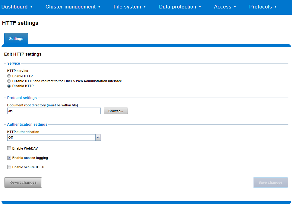
Similarly, you can also use the WebUI to view and edit a subset of the HTTP configuration settings, by navigating to Protocols > HTTP settings:
That said, the implications and impact of disabling each of the services is as follows:
Service | Disabling impacts |
WebUI | The WebUI is completely disabled, and access attempts (default TCP port 8080) are denied with the warning Service Unavailable. Please contact Administrator. If the WebUI is re-enabled, the external platform API service (Platform-API-External) is also started if it is not running. Note that disabling the WebUI does not affect the PlatformAPI service. |
Platform API | External API requests to the cluster are denied, and the WebUI is disabled, because it uses the Platform-API-External service. Note that the Platform-API-Internal service is not impacted if/when the Platform-API-External is disabled, and internal pAPI services continue to function as expected. If the Platform-API-External service is re-enabled, the WebUI will remain inactive until the PowerScaleUI service is also enabled. |
RAN | If RAN is disabled, the WebUI components for File System Explorer and File Browser are also automatically disabled. From the WebUI, attempts to access the OneFS file system explorer (File System > File System Explorer) fail with the warning message Browse is disabled as RAN service is not running. Contact your administrator to enable the service. This same warning also appears when attempting to access any other WebUI components that require directory selection. |
RemoteService | If RemoteService is disabled, the WebUI components for Remote Support and In-Product Activation are disabled. In the WebUI, going to Cluster Management > General Settings and selecting the Remote Support tab displays the message The service required for the feature is disabled. Contact your administrator to enable the service. In the WebUI, going to Cluster Management > Licensing and scrolling to the License Activation section displays the message The service required for the feature is disabled. Contact your administrator to enable the service. |
SWIFT | Deprecated object protocol and disabled by default. |
You can use the CLI command isi http settings view to display the OneFS HTTP configuration:
# isi http settings view
            Access Control: No
      Basic Authentication: No
    WebHDFS Ran HTTPS Port: 8443
                        Dav: No
         Enable Access Log: Yes
                      HTTPS: No
 Integrated Authentication: No
               Server Root: /ifs
                    Service: disabled
           Service Timeout: 8m20s
          Inactive Timeout: 15m
           Session Max Age: 4H
Httpd Controlpath Redirect: No
Similarly, you can manage and change the HTTP configuration using the isi http settings modify CLI command.
For example, to reduce the maximum session age from four to two hours:
# isi http settings view | grep -i age
           Session Max Age: 4H
# isi http settings modify --session-max-age=2H
# isi http settings view | grep -i age
           Session Max Age: 2H
The full set of configuration options for isi http settings includes:
Option | Description |
--access-control <boolean> | Enable Access Control Authentication for the HTTP service. Access Control Authentication requires at least one type of authentication to be enabled. |
--basic-authentication <boolean> | Enable Basic Authentication for the HTTP service. |
--webhdfs-ran-https-port <integer> | Configure Data Services Port for the HTTP service. |
--revert-webhdfs-ran-https-port | Set value to system default for --webhdfs-ran-https-port. |
--dav <boolean> | Comply with Class 1 and 2 of the DAV specification (RFC 2518) for the HTTP service. All DAV clients must go through a single node. DAV compliance is NOT met if you go through SmartConnect, or using 2 or more node IPs. |
--enable-access-log <boolean> | Enable writing to a log when the HTTP server is accessed for the HTTP service. |
--https <boolean> | Enable the HTTPS transport protocol for the HTTP service. |
--https <boolean> | Enable the HTTPS transport protocol for the HTTP service. |
--integrated-authentication <boolean> | Enable Integrated Authentication for the HTTP service. |
--server-root <path> | Document root directory for the HTTP service. Must be within /ifs. |
--service (enabled | disabled | redirect | disabled_basicfile) | Enable/disable the HTTP Service or redirect to WebUI or disabled BasicFileAccess. |
--service-timeout <duration> | The amount of time (in seconds) that the server will wait for certain events before failing a request. A value of 0 indicates that the service timeout value is the Apache default. |
--revert-service-timeout | Set value to system default for --service-timeout. |
--inactive-timeout <duration> | Get the HTTP RequestReadTimeout directive from both the WebUI and the HTTP service. |
--revert-inactive-timeout | Set value to system default for --inactive-timeout. |
--session-max-age <duration> | Get the HTTP SessionMaxAge directive from both WebUI and HTTP service. |
--revert-session-max-age | Set value to system default for --session-max-age. |
--httpd-controlpath-redirect <boolean> | Enable or disable WebUI redirection to the HTTP service. |
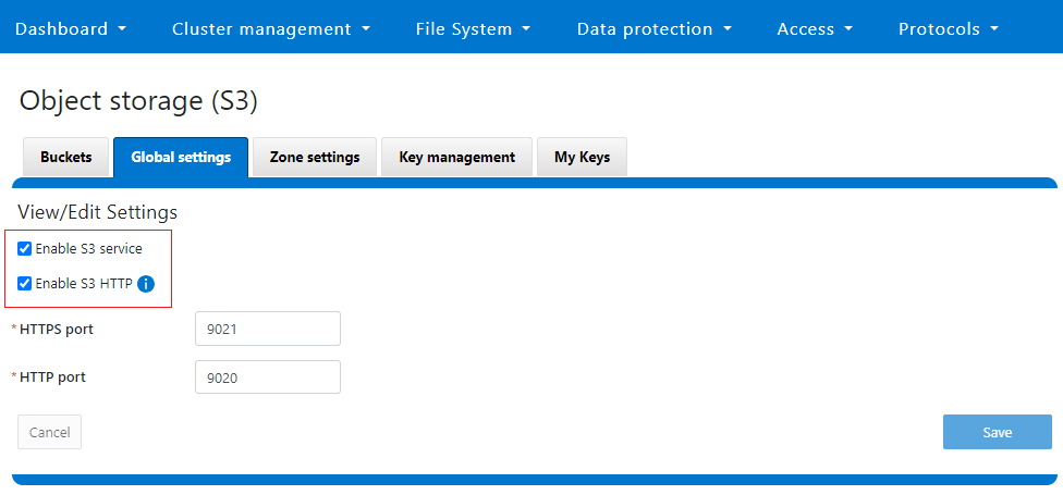
Note that while the OneFS S3 service uses HTTP, it is considered a tier-1 protocol, and as such is managed using its own isi s3 CLI command set and corresponding WebUI area. For example, the following CLI command forces the cluster to only accept encrypted HTTPS/SSL traffic on TCP port 9999 (rather than the default TCP port 9021):
# isi s3 settings global modify --https-only 1 –https-port 9921
# isi s3 settings global view
         HTTP Port: 9020
        HTTPS Port: 9999
        HTTPS only: Yes
S3 Service Enabled: Yes
Additionally, you can entirely disable the S3 service with the following CLI command:
# isi services s3 disable
The service 's3' has been disabled.
Or from the WebUI, under Protocols > S3 > Global settings:
Author: Nick Trimbee

OneFS and PowerScale F-series Management Ports
Mon, 22 Apr 2024 20:12:20 -0000
|Read Time: 0 minutes
Another security enhancement that OneFS 9.5 and later releases brings to the table is the ability to configure 1GbE NIC ports dedicated to cluster management on the PowerScale F900, F710, F600, F210, and F200 all-flash storage nodes and P100 and B100 accelerators. Since these platforms were released, customers have been requesting the ability to activate the 1GbE NIC ports so that the node management activity and front end protocol traffic can be separated on physically distinct interfaces.
For background, since their introduction, the F600 and F900 have shipped with a quad port 1GbE rNDC (rack Converged Network Daughter Card) adapter. However, these 1GbE ports were non-functional and unsupported in OneFS releases prior to 9.5. As such, the node management and front-end traffic was co-mingled on the front-end interface.
In OneFS 9.5 and later, 1GbE network ports are now supported on all of the PowerScale PowerEdge based platforms for the purposes of node management, and are physically separate from the other network interfaces. Specifically, this enhancement applies to the F900, F600, F200 all-flash nodes, and P100 and B100 accelerators.
Under the hood, OneFS has been updated to recognize the 1GbE rNDC NIC ports as usable for a management interface. Note that the focus of this enhancement is on factory enablement and support for existing F600 customers that have the unused 1GbE rNDC hardware. This functionality has also been back-ported to OneFS 9.4.0.3 and later RUPs. Since the introduction of this feature, there have been several requests raised about field upgrades, but that use case is separate and will be addressed in a later release through scripts, updates of node receipts, procedures, and so on.
Architecturally, aside from some device driver and accounting work, no substantial changes were required to the underlying OneFS or platform architecture to implement this feature. This means that in addition to activating the rNDC, OneFS now supports the relocated front-end NIC in PCI slots 2 or 3 for the F200, B100, and P100.
OneFS 9.5 and later recognizes the 1GbE rNDC as usable for the management interface in the OneFS Wizard, in the same way it always has for the H-series and A-series chassis-based nodes.
All four ports in the 1GbE NIC are active, and for the Broadcom board, the interfaces are initialized and reported as bge0, bge1, bge2, and bge3.
The pciconf CLI utility can be used to determine whether the rNDC NIC is present in a node. If it is, a variety of identification and configuration details are displayed. For example, let’s look at the following output from a Broadcom rNDC NIC in an F200 node:
# pciconf -lvV pci0:24:0:0
bge2@pci0:24:0:0: class=0x020000 card=0x1f5b1028 chip=0x165f14e4 rev=0x00 hdr=0x00
      class       = network
      subclass    = ethernet
      VPD ident   = ‘Broadcom NetXtreme Gigabit Ethernet’
      VPD ro PN   = ‘BCM95720’
      VPD ro MN   = ‘1028’
      VPD ro V0   = ‘FFV7.2.14’
      VPD ro V1   = ‘DSV1028VPDR.VER1.0’
      VPD ro V2   = ‘NPY2’
      VPD ro V3   = ‘PMT1’
      VPD ro V4   = ‘NMVBroadcom Corp’
      VPD ro V5   = ‘DTINIC’
      VPD ro V6   = ‘DCM1001008d452101000d45’
We can use the ifconfig CLI utility to determine the specific IP/interface mapping on the Broadcom rNDC interface. For example:
# ifconfig bge0
 TME-1: bge0: flags=8843<UP,BROADCAST,RUNNING,SIMPLEX,MULTICAST> metric 0 mtu 1500
 TME-1:      ether 00:60:16:9e:X:X
 TME-1:      inet 10.11.12.13 netmask 0xffffff00 broadcast 10.11.12.255 zone 1
 TME-1:      inet 10.11.12.13 netmask 0xffffff00 broadcast 10.11.12.255 zone 0
 TME-1:      media: Ethernet autoselect (1000baseT <full-duplex>)
 TME-1:      status: active
In this output, the first IP address of the management interface’s pool is bound to bge0, which is the first port on the Broadcom rNDC NIC.
We can use the isi network pools CLI command to determine the corresponding interface. Within the system zone, the management interface is allocated an address from the configured IP range within its associated interface pool. For example:
# isi network pools list
ID                      SC Zone                  IP Ranges                   Allocation Method
----------------------------------------------------------------------------------------------
groupnet0.mgt.mgt       cluster_mgt_isln.com     10.11.12.13-10.11.12.20     static
# isi network pools view groupnet0.mgt.mgt | grep -i ifaces
               Ifaces: 1:mgmt-1, 2:mgmt-1, 3:mgmt-1, 4:mgmt-1, 5:mgmt-1
Or from the WebUI, under Network configuration > External network:
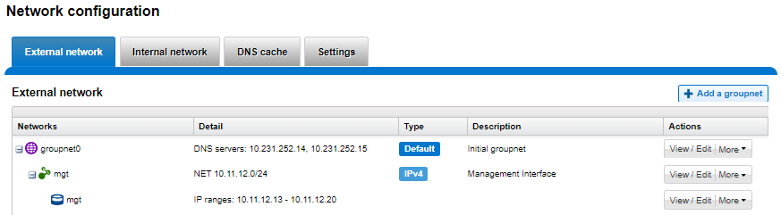
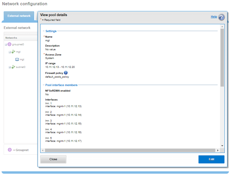
Drilling down into the mgt pool details shows the 1GbE management interfaces as the pool interface members:
Note that the 1GbE rNDC network ports are solely intended as cluster management interfaces. As such, they are not supported for use with regular front-end data traffic.
The F900 and F600 nodes already ship with a four port 1GbE rNDC NIC installed. However, the F200, B100, and P100 platform configurations have also been updated to include a quad port 1GbE rNDC card. These new configurations have been shipping by default since January 2023. This required relocating the front end network’s 25GbE NIC (Mellanox CX4) to PCI slot 2 in the motherboard. Additionally, the OneFS updates needed for this feature have also now allowed the F200 platform to be offered with a 100GbE option too. The 100GbE option uses a Mellanox CX6 NIC in place of the CX4 in slot 2.
With this 1GbE management interface enhancement, the same quad-port rNDC card (typically the Broadcom 5720) that has been shipped in the F900 and F600 since their introduction, is now included in the F200, B100 and P100 nodes as well. All four 1GbE rNDC ports are enabled and active under OneFS 9.5 and later, too.
Node port ordering continues to follow the standard, increasing numerically from left to right. However, be aware that the port labels are not visible externally because they are obscured by the enclosure’s sheet metal.
The following back-of-chassis hardware images show the new placements of the NICs in the various F-series and accelerator platforms:
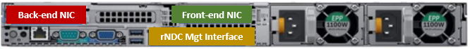
F600
F900
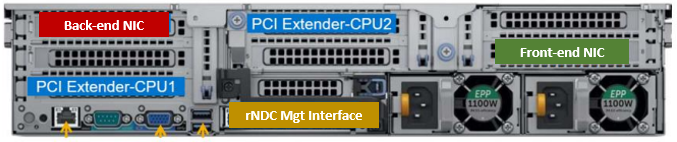
For both the F600 and F900, the NIC placement remains unchanged, because these nodes have always shipped with the 1GbE quad port in the rNDC slot since their launch.
F200
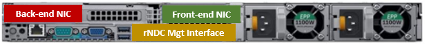
The F200 sees its front-end NIC moved to slot 3, freeing up the rNDC slot for the quad-port 1GbE Broadcom 5720.
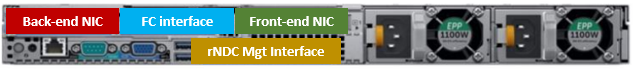
Because the B100 backup accelerator has a fibre-channel card in slot 2, it sees its front-end NIC moved to slot 3, freeing up the rNDC slot for the quad-port 1GbE Broadcom 5720.

Finally, the P100 accelerator sees its front-end NIC moved to slot 3, freeing up the rNDC slot for the quad-port 1GbE Broadcom 5720.
Note that, while there is currently no field hardware upgrade process for adding rNDC cards to legacy F200 nodes or B100 and P100 accelerators, this will be addressed in a future release.
Author: Nick Trimbee

OneFS Security and USB Device Control
Fri, 19 Apr 2024 17:34:44 -0000
|Read Time: 0 minutes
As we’ve seen over the course of the last several articles, OneFS 9.5 delivers a wealth of security focused features. These span the realms of core file system, protocols, data services, platform, and peripherals. Among these security enhancements is the ability to manually or automatically disable a cluster’s USB ports from either the CLI, platform API, or by activating a security hardening policy.
In support of this functionality, the basic USB port control architecture is as follows:
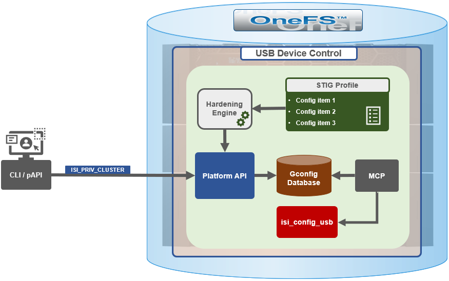
To facilitate this, OneFS 9.5 and subsequent releases see the addition of a new gconfig variable, ‘usb_ports_disabled’, in ‘security_config’, specifically to track the status of USB Ports on a cluster. On receiving an admin request either from the CLI or the platform API handler to disable the USB port, OneFS modifies the security config parameter in gconfig. For example:
# isi_gconfig -t security_config | grep -i usb
usb_ports_disabled (bool) = true
Under the hood, the MCP (master control process) daemon watches for any changes to the ‘isi_security.gcfg’ security config file on the cluster. If the value for the ‘usb_ports_disabled’ variable in the ‘isi_security.gcfg’ file is updated, then MCP executes the ‘isi_config_usb’ utility to enact the desired change. Note that because ‘isi_config_usb’ operates per-node but the MCP actions are global (executed cluster wide), isi_config_usb is invoked across each node by a Python script to enable or disable the cluster’s USB Ports.
The USB Ports enable/disable feature is only supported on PowerScale F900, F600, F200, H700/7000, and A300/3000 clusters running OneFS 9.5 and later, and PowerScale F710 and F210 running OneFS 9.7 or later.
In OneFS 9.5 and later, USB port control can be manually configured from either the CLI or platform API.
Note that there is no WebUI option at this time.
The following table lists the CLI and platform API configuration options for USB port control in OneFS 9.5 and later:
Action | CLI Syntax | Description |
View | isi security settings view | Report the state of a cluster’s USB ports. |
Enable | isi security settings modify --usb-ports-disabled=False | Activate a cluster’s USB ports. |
Disable | isi security settings modify --usb-ports-disabled=True | Disable a cluster’s USB ports. |
For example:
# isi security settings view | grep -i usb
      USB Ports Disabled: No
# isi security settings modify --usb-ports-disabled=True
# isi security settings view | grep -i usb
      USB Ports Disabled: Yes
Similarly, to re-enable a cluster’s USB ports:
# isi security settings modify --usb-ports-disabled=False
# isi security settings view | grep -i usb
      USB Ports Disabled: No
Note that a user account with the OneFS ISI_PRIV_CLUSTER RBAC privilege is required to configure USB port changes on a cluster.
In addition to the ‘isi security settings’ CLI command, there is also a node-local CLI utility:
# whereis isi_config_usb
isi_config_usb: /usr/bin/isi_hwtools/isi_config_usb
As mentioned previously, ‘isi security settings’ acts globally on a cluster, using ‘isi_config_usb’ to effect its changes on each node.
Alternatively, cluster USB ports can also be enabled and disabled using the OneFS platform API with the following endpoints:
API | Method | Argument | Output |
/16/security/settings | GET | No argument required. | JSON object for security settings with USB ports setting. |
/16/security/settings | PUT | JSON object with boolean value for USB ports setting. | None or Error. |
For example:
# curl -k -u <username>:<passwd> https://localhost:8080/platform/security/settings”

 {
 "settings" :
 {
 "fips_mode_enabled" : false,
 "restricted_shell_enabled" : false,
 "usb_ports_disabled" : true
 }
 }
In addition to manual configuration, the USB ports are automatically disabled if the STIG security hardening profile is applied to a cluster.
This is governed by the following section of XML code in the isi_hardening configuration file, which can be found at /etc/isi_hardening/profiles/isi_hardening.xml:
<CONFIG_ITEM id ="isi_usb_ports" version = "1">
              <PapiOperation>
                           <DO>
                                        <URI>/security/settings</URI>
                                        <BODY>{"usb_ports_disabled": true}</BODY>
                                        <KEY>settings</KEY>
                           </DO>
                           <UNDO>
                                        <URI>/security/settings</URI>
                                        <BODY>{"usb_ports_disabled": false}</BODY>
                                        <KEY>settings</KEY>
                           </UNDO>
                           <ACTION_SCOPE>CLUSTER</ACTION_SCOPE>
                           <IGNORE>FALSE</IGNORE>
              </PapiOperation>
 </CONFIG_ITEM>
The ‘isi_config_usb’ CLI utility can be used to display the USB port status on a subset of nodes. For example:
# isi_config_usb --nodes 1-10 --mode display
    Node   |   Current  |  Pending
-----------------------------------
    TME-9  |   UNSUP    | INFO: This platform is not supported to run this script.
    TME-8  |   UNSUP    | INFO: This platform is not supported to run this script.
    TME-1  |     On     |
    TME-3  |     On     |
    TME-2  |     On     |
   TME-10  |     On     |
    TME-7  |   AllOn    |
    TME-5  |   AllOn    |
    TME-6  |   AllOn    |
Unable to connect: TME-4
Note: In addition to port status, the output identifies any nodes that do not support USB port control (nodes 8 and 9 above) or that are unreachable (node 4 above).
When investigating or troubleshooting issues with USB port control, the following log files are the first places to check:
Log file | Description |
/var/log/isi_papi_d.log | Will log any requests to enable or disable USB ports. |
/var/log/isi_config_usb.log | Logs activity from the isi_config_usb script execution. |
/var/log/isi_mcp | Logs activity related to MCP actions on invoking the API. |
Author: Nick Trimbee

OneFS System Configuration Auditing
Thu, 18 Apr 2024 04:55:18 -0000
|Read Time: 0 minutes
OneFS auditing can detect potential sources of data loss, fraud, inappropriate entitlements, access attempts that should not occur, and a range of other anomalies that are indicators of risk. This can be especially useful when the audit associates data access with specific user identities.
In the interests of data security, OneFS provides “chain of custody” auditing by logging specific activity on the cluster. This includes OneFS configuration changes plus NFS, SMB, and HDFS client protocol activity which are required for organizational IT security compliance, as mandated by regulatory bodies like HIPAA, SOX, FISMA, MPAA, and more.
OneFS auditing uses Dell’s Common Event Enabler (CEE) to provide compatibility with external audit applications. A cluster can write audit events across up to five CEE servers per node in a parallel, load-balanced configuration. This allows OneFS to deliver an end to end, enterprise grade audit solution which efficiently integrates with third party solutions like Varonis DatAdvantage.
The following diagram outlines the basic architecture of OneFS audit:
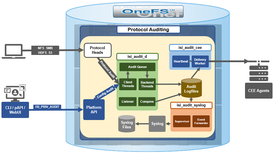 Both system configuration changes, as well as protocol activity, can be easily audited on a PowerScale cluster. However, the protocol path is greyed out above, since it is outside the focus of this article. More information on OneFS protocol auditing can be found here.
As illustrated above, the OneFS audit framework is centered around three main services.
Service | Description |
isi_audit_cee | Service allowing OneFS to support third-party auditing applications. The main method of accessing protocol audit data from OneFS is through a third-party auditing application. |
isi_audit_d | Responsible for per-node audit queues and managing the data store for those queues. It provides a protocol on which clients may produce event payloads within a given context. It establishes a Unix domain socket for queue producers and handles writing and rotation of log files in /ifs/.ifsvar/audit/logs/node###/{config,protocol}/*. |
isi_audit_syslog | Daemon providing forwarding of audit config and protocol events to syslog. |
The basic configuration auditing workflow sees a cluster config change request come in via either the OneFS CLI, WebUI or platform API. The API handler infrastructure passes this request to the isi_audit_d service which intercepts it as a client thread and adds it to the audit queue. It is then processed and passed via a backend thread and written to the audit log files (IFS) as appropriate.
If audit syslog forwarding has been configured, IFS also passes the event to the isi_audit_syslog daemon, where a supervisor process instructs a writer thread to send it to the syslog which in turn updates its pertinent /var/log/ logfiles.
Similarly, if Common Event Enabler (CEE) forwarding has been enabled, IFS will also pass the request to the isi_audit_cee service where a delivery worker threads will intercept it and send the event to the CEE server pool. The isi_audit_cee heartbeat task makes CEE servers available for audit event delivery. Only after a CEE server has received a successful heartbeat will audit events be delivered to it. Every ten seconds, the heartbeat task wakes up and sends each CEE server in the configuration a heartbeat. While CEE servers are available and events are in memory, an attempt will be made to deliver these. Shutdown will only save audit log position if all the events are delivered to CEE since audit should not lose events. It isn't critical that all events are delivered at shutdown since any unsaved events can be resent to CEE on the next start of isi_audit_cee since CEE handles duplicates.
Within OneFS, all audit data is organized by topic and is securely stored in the file system.
# isi audit topics list
Name Max Cached Messages
-----------------------------
protocol 2048
config 1024
-----------------------------
Total: 2
Auditing can detect a variety of potential sources of data loss. These include unauthorized access attempts, inappropriate entitlements, plus a bevy of other fraudulent activities that plague organizations across the gamut of industries. Enterprises are increasingly required to comply with stringent regulatory mandates developed to protect against these sources of data theft and loss.
OneFS system configuration auditing is designed to track and record all configuration events that are handled by the API through the command-line interface (CLI).
# isi audit topics view config
Name: config
Max Cached Messages: 1024
Once enabled, system configuration auditing requires no additional configuration, and auditing events are automatically stored in the config audit topic directories. Audit access and management is governed by the ‘ISI_PRIV_AUDIT’ RBAC privilege, and OneFS provides a default ‘AuditAdmin’ role for this purpose.
Audit events are stored in a binary file under /ifs/.ifsvar/audit/logs. The logs automatically roll over to a new file after the size reaches 1 GB. The audit logs are consumable by auditing applications that support the Dell Common Event Enabler (CEE).
OneFS audit topics and settings can easily be viewed and modified. For example, to increase the configuration auditing maximum cached messages threshold to 2048 from the CLI:
# isi audit topics modify config --max-cached-messages 2048
# isi audit topics view config
Name: config
Max Cached Messages: 2048
Audit configuration can also be modified or viewed per access zone and/or topic.
Operation | CLI Syntax | Method and URI |
Get audit settings | isi audit settings view | GET <cluster-ip:port>/platform/3/audit/settings |
Modify audit settings | isi audit settings modify … | PUT <cluster-ip:port>/platform/3/audit/settings |
View JSON schema for this resource, including query parameters and object properties info. |
| GET <cluster-ip:port>/platform/3/audit/settings?describe |
View JSON schema for this resource, including query parameters and object properties info. |
| GET <cluster-ip:port>/platform/1/audit/topics?describe |
Configuration auditing can be enabled on a cluster from either the CLI or platform API. The current global audit configuration can be viewed as follows:
1# isi audit settings global view
Protocol Auditing Enabled: No
Audited Zones: -
CEE Server URIs: -
Hostname:
Config Auditing Enabled: No
Config Syslog Enabled: No
Config Syslog Servers: -
Config Syslog TLS Enabled: No
Config Syslog Certificate ID:
Protocol Syslog Servers: -
Protocol Syslog TLS Enabled: No
Protocol Syslog Certificate ID:
System Syslog Enabled: No
System Syslog Servers: -
System Syslog TLS Enabled: No
System Syslog Certificate ID:
Auto Purging Enabled: No
Retention Period: 180
System Auditing Enabled: No
In this case, configuration auditing is disabled – its default setting. The following CLI syntax will enable (and verify) configuration auditing across the cluster:
# isi audit settings global modify --config-auditing-enabled 1
# isi audit settings global view | grep -i 'config audit'
Config Auditing Enabled: Yes
In the next article, we’ll look at the config audit management, event viewing, and troubleshooting.
To enable configuration change audit redirection to syslog:
# isi audit settings global modify --config-auditing-enabled true
# isi audit settings global modify --config-syslog-enabled true
# isi audit settings global view | grep -i 'config audit'
Config Auditing Enabled: Yes
Similarly, to disable configuration change audit redirection to syslog:
# isi audit settings global modify --config-syslog-enabled false
# isi audit settings global modify --config-auditing-enabled false
configure audit
2.
#isi audit setting modify --add-cee-server-uris='http://seavee5.west.isilon.com:12228/cee'
4.
# isi audit settings modify --add-audited-zones=auditgti
4' if you don't want audit that much
# isi audit setting modify --remove-audited-zones=System
config zone
3.
#isi zone zones create --all-auth-providers=true --audit-failure=all --audit-success=all --path=/ifs/data --name=auditgti
3'. if you dont' want to audit that much
#isi zone zones create --all-auth-providers=true --audit-failure=read,logon --audit-success=write,delete --path=/ifs/data --name=auditgti
network pool
5.
#isi network create pool --name=subnet0:auditpool --access-zone=auditgit --iface=<your interface> --range=<your range>
5' you can also audit System by default, so this step can be ignored
other settings
#isi audit setting modify --hostname="<any name you want really, this just gets inserted into the payload>"
#isi audit setting modify --cee-log-time="Protocol@1900-01-01 00:00:01"
The platform API can also be used to configure and manage auditing. For example, to enable configuration auditing on a cluster:
PUT /platform/1/audit/settings
Authorization: Basic QWxhZGRpbjpvcGVuIHN1c2FtZQ==
{
'config_auditing_enabled': True
}
Response example
The HTTP ‘204 response code from the cluster indicates that the request was successful, and that configuration auditing is now enabled on the cluster. No message body is returned for this request.
204 No Content
Content-type: text/plain,
Allow: 'GET, PUT, HEAD'
Similarly, to modify the config audit topic’s maximum cached messages threshold to a value of ‘1000’ via the API:
PUT /1/audit/topics/config
Authorization: Basic QWxhZGRpbjpvcGVuIHN1c2FtZQ==
{
"max_cached_messages": 1000
}
Again, no message body is returned from OneFS for this request.
204 No Content
Content-type: text/plain,
Allow: 'GET, PUT, HEAD'
Note that, in the unlikely event that a cluster experiences an outage during which it loses quorum, auditing will be suspended until it is regained. Events similar to the following will be written to the /var/log/audit_d.log file:
940b5c700]: Lost quorum! Audit logging will be disabled until /ifs is writeable again.
2023-08-28T15:37:32.132780+00:00 <1.6> TME-1(id1) isi_audit_d[6495]: [0x345940b5c700]: Regained quorum. Logging resuming.
When it comes to reading audit events on the cluster, OneFS natively provides the handy ‘isi_audit_viewer’ utility. For example, the following audit viewer output shows the events logged when the cluster admin added the ‘/ifs/tmp’ path to the SmartDedupe configuration, and created a new user named ‘test’1’:
# isi_audit_viewer
[0: Tue Aug 29 23:01:16 2023] {"id":"f54a6bec-46bf-11ee-920d-0060486e0a26","timestamp":1693350076315499,"payload":{"user":{"token": {"UID":0, "GID":0, "SID": "SID:S-1-22-1-0", "GSID": "SID:S-1-22-2-0", "GROUPS": ["SID:S-1-5-11", "GID:5", "GID:10", "GID:20", "GID:70"], "protocol": 17, "zone id": 1, "client": "10.135.6.255", "local": "10.219.64.11" }},"uri":"/1/dedupe/settings","method":"PUT","args":{}
,"body":{"paths":["/ifs/tmp"]}
}}
[1: Tue Aug 29 23:01:16 2023] {"id":"f54a6bec-46bf-11ee-920d-0060486e0a26","timestamp":1693350076391422,"payload":{"status":204,"statusmsg":"No Content","body":{}}}
[2: Tue Aug 29 23:03:43 2023] {"id":"4cfce7a5-46c0-11ee-920d-0060486e0a26","timestamp":1693350223446993,"payload":{"user":{"token": {"UID":0, "GID":0, "SID": "SID:S-1-22-1-0", "GSID": "SID:S-1-22-2-0", "GROUPS": ["SID:S-1-5-11", "GID:5", "GID:10", "GID:20", "GID:70"], "protocol": 17, "zone id": 1, "client": "10.135.6.255", "local": "10.219.64.11" }},"uri":"/18/auth/users","method":"POST","args":{}
,"body":{"name":"test1"}
}}
[3: Tue Aug 29 23:03:43 2023] {"id":"4cfce7a5-46c0-11ee-920d-0060486e0a26","timestamp":1693350223507797,"payload":{"status":201,"statusmsg":"Created","body":{"id":"SID:S-1-5-21-593535466-4266055735-3901207217-1000"}
}}
The audit log entries, such as those above, typically comprise the following components:
- Timestamp (Human readable)
- Unique Entry ID
- Timestamp (Unix Epoch Time)
- Node Number
- The user tokens of the person executing the command
- User persona (Unix/Windows)
- Primary group persona (Unix/Windows)
- Supplemental group personas (Unix/Windows)
- RBAC privileges of the person executing the command
- Interface used to generate the command
- 10 = PAPI / WebUI
- 16 = Console
- 17 = SSH
- Access Zone that the command was executed against
- Where the user connected from
- The local node address where the command was executed
- Command
- Command arguments
- Command body
The ‘isi_audit_viewer’ utility automatically reads the ‘config’ log topic by default, but can also be used read the ‘protocol’ log topic too. Its CLI command syntax is as follows:
# isi_audit_viewer -h
Usage: isi_audit_viewer [ -n <nodeid> | -t <topic> | -s <starttime>|
-e <endtime> | -v ]
-n <nodeid> : Specify node id to browse (default: local node)
-t <topic> : Choose topic to browse.
Topics are "config" and "protocol" (default: "config")
-s <start> : Browse audit logs starting at <starttime>
-e <end> : Browse audit logs ending at <endtime>
-v verbose : Prints out start / end time range before printing
records
Note that, on large clusters where there is heavy (up to the 100,000’s) of audit writes, when running the isi_audit_viewer utility across the cluster with ‘isi_for_array’, it can potentially lead to memory starvation and other issues – especially if outputting to a directory under /ifs. As such, consider directing the output to a non-IFS location such as /var/temp. Also, the isi_audit_viewer ‘-s’ (start time) and ‘-e’ (end time) flags can be used to limit a search (for 1-5 minutes), helping reduce the size of data.
In addition to reading audit events, the view is also a useful tool to assist with troubleshoot any auditing issues. Additionally, any errors that are encountered while processing audit events, and when delivering them to an external CEE server, are written to the log file ‘/var/log/isi_audit_cee.log’. Additionally, the protocol specific logs will contain any issues the audit filter has collecting while auditing events.

OneFS System Configuration Auditing – Part 2
Thu, 18 Apr 2024 22:28:35 -0000
|Read Time: 0 minutes
In the previous article of this series, we looked at the architecture and operation of OneFS configuration auditing. Now, we’ll turn our attention to its management, event viewing, and troubleshooting.
The CLI command set for configuring ‘isi audit’ is split between two areas:
Area | Detail | Syntax |
Events | Specifies which events get logged, across three categories: •Audit Failure •Audit Success •Syslog Audit Events | isi audit settings … |
Global | Configuration of global audit parameters, including topics, zones, CEE, syslog, puring, retention, and more. | isi audit settings global ... |
The ‘view’ argument for each command returns the following output:
Events:
# isi audit settings view
Audit Failure: create_file, create_directory, open_file_write, open_file_read, close_file_unmodified, close_file_modified, delete_file, delete_directory, rename_file, rename_directory, set_security_file, set_security_directory
Audit Success: create_file, create_directory, open_file_write, open_file_read, close_file_unmodified, close_file_modified, delete_file, delete_directory, rename_file, rename_directory, set_security_file, set_security_directory
Syslog Audit Events: create_file, create_directory, open_file_write, open_file_read, close_file_unmodified, close_file_modified, delete_file, delete_directory, rename_file, rename_directory, set_security_file, set_security_directory
Syslog Forwarding Enabled: No
Global:
# isi audit settings global view
Protocol Auditing Enabled: Yes
Audited Zones: -
CEE Server URIs: -
Hostname:
Config Auditing Enabled: Yes
Config Syslog Enabled: No
Config Syslog Servers: -
Config Syslog TLS Enabled: No
Config Syslog Certificate ID:
Protocol Syslog Servers: -
Protocol Syslog TLS Enabled: No
Protocol Syslog Certificate ID:
System Syslog Enabled: No
System Syslog Servers: -
System Syslog TLS Enabled: No
System Syslog Certificate ID:
Auto Purging Enabled: No
Retention Period: 180
System Auditing Enabled: No
While configuration auditing is disabled on OneFS by default, the following CLI syntax can be used to enable and verify config auditing across the cluster:
# isi audit settings global modify --config-auditing-enabled 1
# isi audit settings global view | grep -i 'config audit'
Config Auditing Enabled: Yes
Similarly, to enable configuration change audit redirection to syslog:
# isi audit settings global modify --config-auditing-enabled true
# isi audit settings global modify --config-syslog-enabled true
# isi audit settings global view | grep -i 'config audit'
Config Auditing Enabled: Yes
Or to disable redirection to syslog:
# isi audit settings global modify --config-syslog-enabled false
# isi audit settings global modify --config-auditing-enabled false
CEE servers can be configured as follows:
#isi audit settings global modify --add-cee-server-uris='<URL>’
For example:
#isi audit settings global modify --add-cee-server
-uris='http://cee1.isilon.com:12228/cee'
Auditing can be constrained by access zone, too:
# isi audit settings modify --add-audited-zones=audit_az1
Note that, when auditing is enabled, the system zone is included by default. However, it can be excluded, if desired:
# isi audit setting modify --remove-audited-zones=System
Access zone’s audit parameters can also be configured via the ‘isi zones’ CLI command set. For example:
#isi zone zones create --all-auth-providers=true --audit-failure=all --audit-success=all --path=/ifs/data --name=audit_az1
Granular audit event type configuration can be specified, if desired, to narrow the scope and reduce the amount of audit logging.
For example, the following command syntax constrains auditing to read and logon failures and successful writes and deletes under path /ifs/data in the audit_az1 access zone:
#isi zone zones create --all-auth-providers=true --audit-failure=read,logon --audit-success=write,delete --path=/ifs/data --name=audit_az1
In addition to the CLI, the OneFS platform API can also be used to configure and manage auditing. For example, to enable configuration auditing on a cluster:
PUT /platform/1/audit/settings
Authorization: Basic QWxhZGRpbjpvcGVuIHN1c2FtZQ==
{
'config_auditing_enabled': True
}
The following ‘204’ HTTP response code from the cluster indicates that the request was successful, and that configuration auditing is now enabled on the cluster. No message body is returned for this request.
204 No Content
Content-type: text/plain,
Allow: 'GET, PUT, HEAD'
Similarly, to modify the config audit topic’s maximum cached messages threshold to a value of ‘1000’ via the API:
PUT /1/audit/topics/config
Authorization: Basic QWxhZGRpbjpvcGVuIHN1c2FtZQ==
{
"max_cached_messages": 1000
}
Again, no message body is returned from OneFS for this request.
204 No Content
Content-type: text/plain,
Allow: 'GET, PUT, HEAD'
Note that, in the unlikely event that a cluster experiences an outage during which it loses quorum, auditing will be suspended until it is regained. Events similar to the following will be written to the /var/log/audit_d.log file:
940b5c700]: Lost quorum! Audit logging will be disabled until /ifs is writeable again.
2023-08-28T15:37:32.132780+00:00 <1.6> TME-1(id1) isi_audit_d[6495]: [0x345940b5c700]: Regained quorum. Logging resuming.
When it comes to reading audit events on the cluster, OneFS natively provides the handy ‘isi_audit_viewer’ utility. For example, the following audit viewer output shows the events logged when the cluster admin added the ‘/ifs/tmp’ path to the SmartDedupe configuration, and created a new user named ‘test’1’:
# isi_audit_viewer
[0: Tue Aug 29 23:01:16 2023] {"id":"f54a6bec-46bf-11ee-920d-0060486e0a26","timestamp":1693350076315499,"payload":{"user":{"token": {"UID":0, "GID":0, "SID": "SID:S-1-22-1-0", "GSID": "SID:S-1-22-2-0", "GROUPS": ["SID:S-1-5-11", "GID:5", "GID:10", "GID:20", "GID:70"], "protocol": 17, "zone id": 1, "client": "10.135.6.255", "local": "10.219.64.11" }},"uri":"/1/dedupe/settings","method":"PUT","args":{}
,"body":{"paths":["/ifs/tmp"]}
}}
[1: Tue Aug 29 23:01:16 2023] {"id":"f54a6bec-46bf-11ee-920d-0060486e0a26","timestamp":1693350076391422,"payload":{"status":204,"statusmsg":"No Content","body":{}}}
[2: Tue Aug 29 23:03:43 2023] {"id":"4cfce7a5-46c0-11ee-920d-0060486e0a26","timestamp":1693350223446993,"payload":{"user":{"token": {"UID":0, "GID":0, "SID": "SID:S-1-22-1-0", "GSID": "SID:S-1-22-2-0", "GROUPS": ["SID:S-1-5-11", "GID:5", "GID:10", "GID:20", "GID:70"], "protocol": 17, "zone id": 1, "client": "10.135.6.255", "local": "10.219.64.11" }},"uri":"/18/auth/users","method":"POST","args":{}
,"body":{"name":"test1"}
}}
[3: Tue Aug 29 23:03:43 2023] {"id":"4cfce7a5-46c0-11ee-920d-0060486e0a26","timestamp":1693350223507797,"payload":{"status":201,"statusmsg":"Created","body":{"id":"SID:S-1-5-21-593535466-4266055735-3901207217-1000"}
}}
The audit log entries, such as those above, typically comprise the following components:
Order | Component | Detail |
1 | Timestamp | Timestamp in human readable form |
2 | ID | Unique entry ID |
3 | Timestamp | Timestamp in UNIX epoch time |
4 | Node | Node number |
5 | User tokens | The user tokens of the Roles and rights of user executing the command. 1. User persona (Unix/Windows 2. Primary group persona (Unix/Windows 3. Supplemental group personas (Unix/Windows) 4. RBAC privileges of the user executing the command |
6 | Interface | Interface used to generate the command: 1. 10 = pAPI / WebUI 2. 16 = Console CLI 3. 17 = SSH CLI |
7 | Zone | Access zone that the command was executed against |
8 | Client IP | Where the user connected from |
9 | Local node | Local node address where the command was executed |
10 | Command | Command syntax |
11 | Arguments | Command arguments |
12 | Body | Command body |
The ‘isi_audit_viewer’ utility automatically reads the ‘config’ log topic by default, but can also be used read the ‘protocol’ log topic too. Its CLI command syntax is as follows:
# isi_audit_viewer -h
Usage: isi_audit_viewer [ -n <nodeid> | -t <topic> | -s <starttime>|
-e <endtime> | -v ]
-n <nodeid> : Specify node id to browse (default: local node)
-t <topic> : Choose topic to browse.
Topics are "config" and "protocol" (default: "config")
-s <start> : Browse audit logs starting at <starttime>
-e <end> : Browse audit logs ending at <endtime>
-v verbose : Prints out start / end time range before printing
records
Note that, on large clusters where there is heavy (in the 100,000’s) of audit writes, when running the isi_audit_viewer utility across the cluster with ‘isi_for_array’, it can potentially lead to memory starvation and other issues – especially if outputting to a directory under /ifs. As such, consider directing the output to a non-IFS location such as /var/temp. Also, the isi_audit_viewer ‘-s’ (start time) and ‘-e’ (end time) flags can be used to limit a search (ie. for 1-5 minutes), helping reduce the size of data.
In addition to reading audit events, the view is also a useful tool to assist with troubleshoot any auditing issues. Additionally, any errors that are encountered while processing audit events, and when delivering them to an external CEE server, are written to the log file ‘/var/log/isi_audit_cee.log’. Additionally, the protocol specific logs will contain any issues the audit filter has collecting while auditing events.
Author: Nick Trimbee

OneFS Log Gather Transmission
Wed, 17 Apr 2024 15:45:51 -0000
|Read Time: 0 minutes
The OneFS isi_gather_info utility is the ubiquitous method for collecting and uploading a PowerScale cluster’s context and configuration to assist with the identification and resolution of bugs and issues. As such, it performs the following roles:
- Executes many commands, scripts, and utilities on a cluster, and saves their results
- Collates, or gathers, all these files into a single ‘gzipped’ package
- Optionally transmits this log gather package back to Dell using a choice of several transport methods
By default, a log gather tarfile is written to the /ifs/data/Isilon_Support/pkg/ directory. It can also be uploaded to Dell by the following means:
Upload mechanism | Description | TCP port | OneFS release support |
SupportAssist / ESRS | Uses Dell Secure Remote Support (SRS) for gather upload. | 443/8443 | Any |
FTP | Use FTP to upload the completed gather. | 21 | Any |
FTPS | Use SSH-based encrypted FTPS to upload the gather. | 22 | Default in OneFS 9.5 and later |
HTTP | Use HTTP to upload the gather. | 80/443 | Any |
As indicated in this table, OneFS 9.5 and later releases now leverage FTPS as the default option for FTP upload, thereby protecting the upload of cluster configuration and logs with an encrypted transmission session.
Under the hood, the log gather process comprises an eight phase workflow, with transmission comprising the penultimate ‘Upload’ phase:
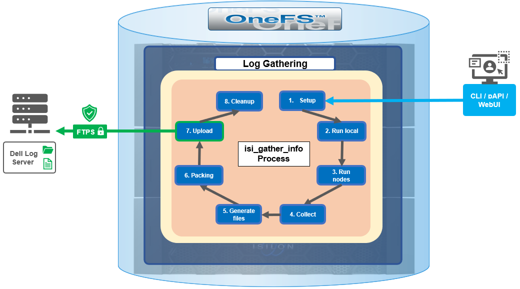
The details of each phase are as follows:
Phase | Description |
1. Setup | Reads from the arguments passed in, and from any config files on disk, and sets up the config dictionary, which will be used throughout the rest of the codebase. Most of the code for this step is contained in isilon/lib/python/gather/igi_config/configuration.py. This is also the step in which the program is most likely to exit, if some config arguments end up being invalid. |
2. Run local | Executes all the cluster commands, which are run on the same node that is starting the gather. All these commands run in parallel (up to the current parallelism value). This is typically the second longest running phase. |
3. Run nodes | Executes the node commands across all of the cluster’s nodes. This runs on each node, and while these commands run in parallel (up to the current parallelism value), they do not run in parallel with the ‘Run local’ step. |
4. Collect | Ensures that all of the results end up on the overlord node (the node that started the gather). If the gather is using /ifs, it is very fast; if it is not using /ifs, it needs to SCP all the node results to a single node. |
5. Generate Extra Files | Generates nodes_info.xml and package_info.xml. These two files are present in every gather, and provide important metadata about the cluster. |
6. Packing | Packs (tars and gzips) all the results. This is typically the longest running phase, often by an order of magnitude. |
7. Upload | Transports the tarfile package to its specified destination using SupportAssist, ESRS, FTPS, FTP, HTTP, and so on. Depending on the geographic location, this phase might also be lengthy. |
8. Cleanup | Cleans up any intermediary files that were created on the cluster. This phase will run even if the gather fails, or is interrupted. |
Because the isi_gather_info tool is primarily intended for troubleshooting clusters with issues, it runs as root (or compadmin in compliance mode), because it needs to be able to execute under degraded conditions (such as without GMP, during upgrade, and under cluster splits, and so on). Given these atypical requirements, isi_gather_info is built as a standalone utility, rather than using the platform API for data collection.
While FTPS is the new default and recommended transport, the legacy plaintext FTP upload method is still available in OneFS 9.5 and later. As such, Dell’s log server, ftp.isilon.com, also supports both encrypted FTPS and plaintext FTP, so will not impact older release FTP log upload behavior.
This OneFS 9.5 FTPS security enhancement encompasses three primary areas where an FTPS option is now supported:
- Directly executing the /usr/bin/isi_gather_info utility
- Running using the isi diagnostics gather CLI command set
- Creating a diagnostics gather through the OneFS WebUI
For the isi_gather_info utility, two new options are included in OneFS 9.5 and later releases:
New option for isi_gather_info | Description | Default value |
--ftp-insecure | Enables the gather to use unencrypted FTP transfer. | False |
--ftp-ssl-cert | Enables the user to specify the location of a special SSL certificate file. | Empty string. Not typically required. |
Similarly, there are two corresponding options in OneFS 9.5 and later for the isi diagnostics CLI command:
New option for isi diagnostics | Description | Default value |
--ftp-upload-insecure | Enables the gather to use unencrypted FTP transfer. | No |
--ftp-upload-ssl-cert | Enables the user to specify the location of a special SSL certificate file. | Empty string. Not typically required. |
Based on these options, the following table provides some command syntax usage examples, for both FTPS and FTP uploads:
FTP upload type | Description | Example isi_gather_info syntax | Example isi diagnostics syntax |
Secure upload (default) | Upload cluster logs to the Dell log server (ftp.isilon.com) using encrypted FTP (FTPS). | # isi_gather_info Or # isi_gather_info --ftp | # isi diagnostics gather start Or # isi diagnostics gather start --ftp-upload-insecure=no |
Secure upload | Upload cluster logs to an alternative server using encrypted FTPS. | # isi_gather_info --ftp-host <FQDN> --ftp-ssl-cert <SSL_CERT_PATH> | # isi diagnostics gather start --ftp-upload-host=<FQDN> --ftp-ssl-cert= <SSL_CERT_PATH> |
Unencrypted upload | Upload cluster logs to the Dell log server (ftp.isilon.com) using plaintext FTP. | # isi_gather_info --ftp-insecure | # isi diagnostics gather start --ftp-upload-insecure=yes |
Unencrypted upload | Upload cluster logs to an alternative server using plaintext FTP. | # isi_gather_info --ftp-insecure --ftp-host <FQDN> | # isi diagnostics gather start --ftp-upload-host=<FQDN> --ftp-upload-insecure=yes |
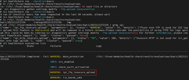
Note that OneFS 9.5 and later releases provide a warning if the cluster admin elects to continue using non-secure FTP for the isi_gather_info tool. Specifically, if the --ftp-insecure option is configured, the following message is displayed, informing the user that plaintext FTP upload is being used, and that the connection and data stream will not be encrypted:
# isi_gather_info --ftp-insecure
You are performing plain text FTP logs upload.
This feature is deprecated and will be removed
in a future release. Please consider the possibility
of using FTPS for logs upload. For further information,
please contact PowerScale support
...
In addition to the command line, log gathers can also be configured using the OneFS WebUI by navigating to Cluster management > Diagnostics > Gather settings.
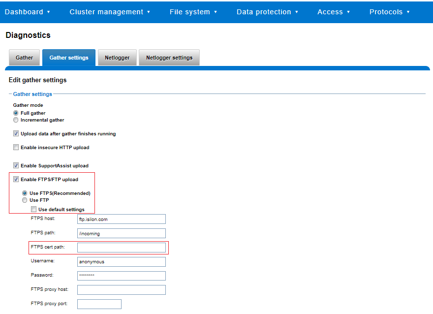
The Edit gather settings page in OneFS 9.5 and later has been updated to reflect FTPS as the default transport method, plus the addition of radio buttons and text boxes to accommodate the new configuration options.
If plaintext FTP upload is configured, the healthcheck command will display a warning that plaintext upload is used and is no longer a recommended option. For example:
For reference, the OneFS 9.5 and later isi_gather_info CLI command syntax includes the following options:
Option | Description |
--upload <boolean> | Enable gather upload. |
--esrs <boolean> | Use ESRS for gather upload. |
--noesrs | Do not attempt to upload using ESRS. |
--supportassist | Attempt SupportAssist upload. |
--nosupportassist | Do not attempt to upload using SupportAssist. |
--gather-mode (incremental | full) | Type of gather: incremental or full. |
--http-insecure <boolean> | Enable insecure HTTP upload on completed gather. |
--http-host <string> | HTTP Host to use for HTTP upload. |
--http-path <string> | Path on HTTP server to use for HTTP upload. |
--http-proxy <string> | Proxy server to use for HTTP upload. |
--http-proxy-port <integer> | Proxy server port to use for HTTP upload. |
--ftp <boolean> | Enable FTP upload on completed gather. |
--noftp | Do not attempt FTP upload. |
--set-ftp-password | Interactively specify alternate password for FTP. |
--ftp-host <string> | FTP host to use for FTP upload. |
--ftp-path <string> | Path on FTP server to use for FTP upload. |
--ftp-port <string> | Specifies alternate FTP port for upload. |
--ftp-proxy <string> | Proxy server to use for FTP upload. |
--ftp-proxy-port <integer> | Proxy server port to use for FTP upload. |
--ftp-mode <value> | Mode of FTP file transfer. Valid values are both, active, and passive. |
--ftp-user <string> | FTP user to use for FTP upload. |
--ftp-pass <string> | Specify alternative password for FTP. |
--ftp-ssl-cert <string> | Specifies the SSL certificate to use in FTPS connection. |
--ftp-upload-insecure <boolean> | Whether to attempt a plaintext FTP upload. |
--ftp-upload-pass <string> | FTP user to use for FTP upload password. |
--set-ftp-upload-pass | Specify the FTP upload password interactively. |
When a logfile gather arrives at Dell, it is automatically unpacked by a support process and analyzed using the logviewer tool.
Author: Nick Trimbee

PowerScale Security Baseline Checklist

Tue, 16 Apr 2024 22:36:48 -0000
|Read Time: 0 minutes
As a security best practice, a quarterly security review is recommended. Forming an aggressive security posture for a PowerScale cluster is composed of different facets that may not be applicable to every organization. An organization’s industry, clients, business, and IT administrative requirements determine what is applicable. To ensure an aggressive security posture for a PowerScale cluster, use the checklist in the following table as a baseline for security.
This table serves as a security baseline and must be adapted to specific organizational requirements. See the Dell PowerScale OneFS: Security Considerations | Dell Technologies Info Hub white paper for a comprehensive explanation of the concepts in the table below.
Further, cluster security is not a single event. It is an ongoing process: Monitor this blog for updates. As new updates become available, this post will be updated. Consider implementing an organizational security review on a quarterly basis.
The items listed in the following checklist are not in order of importance or hierarchy but rather form an aggressive security posture as more features are implemented.
Security feature | Configuration | References and notes | Complete (Y/N) | Notes |
Data at Rest Encryption | Implement external key manager with SEDs | Overview | Dell PowerScale OneFS: Security Considerations | Dell Technologies Info Hub |
|
|
Data in flight encryption | Encrypt protocol communication and data replication | Dell PowerScale: Solution Design and Considerations for SMB Environments (delltechnologies.com)
PowerScale OneFS NFS Design Considerations and Best Practices | Dell Technologies Info Hub
Dell PowerScale SyncIQ: Architecture, Configuration, and Considerations | Dell Technologies Info Hub |
|
|
Role Based Access Control (RBAC) | Assign the lowest possible access required for each role | PowerScale OneFS Authentication, Identity Management, and Authorization | Dell Technologies Info Hub |
|
|
Multifactor authentication |
|
|
| |
Cybersecurity | PowerScale Cyber Protection Suite Reference Architecture | Dell Technologies Info Hub |
|
| |
Monitoring | Monitor cluster activity |
|
|
|
Cluster configuration backup and recovery | Ensure quarterly cluster backups | Backing Up and Restoring PowerScale Cluster Configurations in OneFS 9.7 | Dell Technologies Info Hub |
|
|
Secure Boot | Configure PowerScale Secure Boot | Overview | Dell PowerScale OneFS: Security Considerations | Dell Technologies Info Hub |
|
|
Auditing | Configure auditing |
|
| |
Custom applications | Create a custom application for cluster monitoring | GitHub - Isilon/isilon_sdk: Official repository for isilon_sdk |
|
|
SED and cluster Universal Key rekey | Set a frequency to automatically rekey the Universal Key for SEDs and the cluster | Cluster services rekey | Dell PowerScale OneFS: Security Considerations | Dell Technologies Info Hub |
|
|
Perform a quarterly security review | Review all organizational security requirements and current implementation. Check this paper and checklist for updates: |
|
| |
General cluster security best practices | See the best practices section of the Security Configuration Guide for the relevant release, at PowerScale OneFS Info Hubs | Dell US |
|
| |
Login, authentication, and privileges best practices |
|
| ||
SNMP security best practices |
|
| ||
SSH security best practices |
|
| ||
Data-access protocols best practices |
|
| ||
Web interface security best practices |
|
| ||
Anti-virus | PowerScale: AntiVirus Solutions | Dell Technologies Info Hub |
|
| |
Author: Aqib Kazi – Senior Principal Engineering Technologist

OneFS SyncIQ and Windows File Create Date
Tue, 16 Apr 2024 17:15:51 -0000
|Read Time: 0 minutes
In the POSIX world, files typically possess three fundamental timestamps:
Timestamp | Alias | Description |
Access | atime | Access timestamp of the last read. |
Change | ctime | Status change timestamp of the last update to the file's metadata. |
Modify | mtime | Modification timestamp of the last write. |
These timestamps can be easily viewed from a variety of file system tools and utilities. For example, in this case running ‘stat’ from the OneFS CLI:
# stat -x tstr
File: "tstr"
Size: 0 FileType: Regular File
Mode: (0600/-rw-------) Uid: ( 0/ root) Gid: ( 0/ wheel)
Device: 18446744073709551611,18446744072690335895 Inode: 5103485107 Links: 1
Access: Mon Sep 11 23:12:47 2023
Modify: Mon Sep 11 23:12:47 2023
Change: Mon Sep 11 23:12:47 2023
A typical instance of a change, or “ctime”, timestamp update occurs when a file’s access permissions are altered. Since modifying the permissions doesn’t physically open the file (ie. access the file’s data), its “atime” field is not updated. Similarly, since no modification is made to the file’s contents the “mtime” also remains unchanged. However, the file’s metadata has been changed, and the ctime field is used to record this event. As such, the “ctime” stamp allows a workflow such as a backup application to know to make a fresh copy of the file, including its updated permission values. Similarly, a file rename is another operation that modifies its “ctime” entry without affecting the other timestamps.
Certain other file systems also include a fourth timestamp: namely the “birthtime” of when the file was created. Birthtime (by definition) should never change. It’s also an attribute which organizations and their storage administrators may or may not care about.
Within the Windows file system realm, this “birthtime” timestamp, is affectionally known as “create date”. The create date of a file is essentially the date and time when its inode is “born”.
Note: that this is not a recognized POSIX attribute, like ctime or mtime, rather it is something that was introduced as part of Windows compatibility requirements. And, because it’s a birthtime, linking operations do not necessarily affect it unless a new inode is not created.
As shown below, this create, or birth, date can differ from a file’s modified or accessed dates because the creation date is when that file’s inode version originated. So, for instance, if a file is copied, the new file’s create date will be set to the current time since it has a new inode. This can be seen in the following example where a file is copied from a flash drive mounted on a Windows client’s file system under drive “E:”, to a cluster’s SMB share mounted at drive “Z:”.
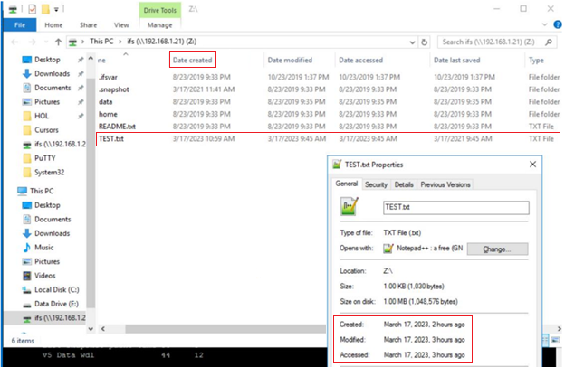
The “Date created” date above is ahead in time of both the “accessed” and “modified”, because the latter two were merely inherited from the source file, whereas the create date was set when the copy was made.
The corresponding “date”, “stat”, and “isi get” CLI output from the cluster confirms this:
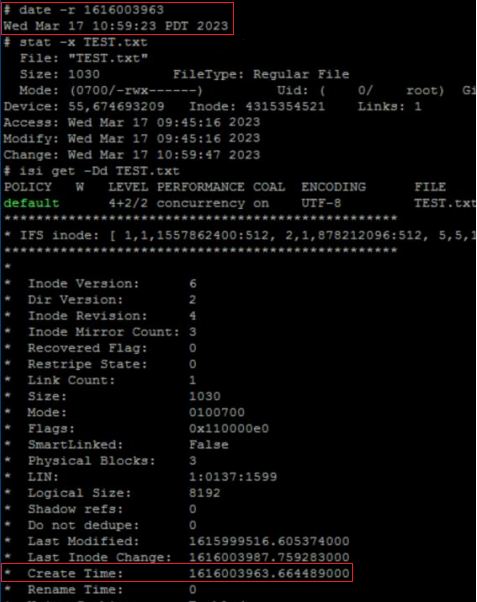
# stat TEST.txt
18446744072690400151 5103485107 -rw------- 1 root wheel 18446744073709551615 0 "Sep 11 23:12:47 2023" "Sep 11 23:12:47 2023" "Sep 11 23:12:47 2023" "Sep 11 23:12:47 2023" 8192 48 0xe0 tstr
# isi get -Dd TEST.txt
POLICY W LEVEL PERFORMANCE COAL ENCODING FILE IADDRS
default 16+2/2 concurrency on UTF-8 tstr <34,12,58813849600:8192>, <35,3,58981457920:8192>, <69,12,57897025536:8192> ct: 1694473967 rt: 0
*************************************************
* IFS inode: [ 34,12,58813849600:8192, 35,3,58981457920:8192, 69,12,57897025536:8192 ]
*************************************************
*
* Inode Version: 8
* Dir Version: 2
* Inode Revision: 1
* Inode Mirror Count: 3
* Recovered Flag: 0
* Restripe State: 0
* Link Count: 1
* Size: 0
* Mode: 0100600
* Flags: 0xe0
* SmartLinked: False
* Physical Blocks: 0
* Phys. Data Blocks: 0
* Protection Blocks: 0
* LIN: 1:3031:00b3
* Logical Size: 0
* Shadow refs: 0
* Do not dedupe: 0
* In CST stats: False
* Last Modified: 1694473967.071973000
* Last Inode Change: 1694473967.071973000
* Create Time: 1694473967.071973000
* Rename Time: 0
<snip>
In releases before OneFS 9.5, when a file is replicated, its create date is timestamped when that file was copied from the source cluster. This means when the replication job ran, or, more specifically, when the individual job worker thread got around to processing that specific file.
By way of contrast, OneFS 9.5 and later releases ensure that SyncIQ fully replicates the full array of metadata, preserving all values, including that of the birth time / create date.
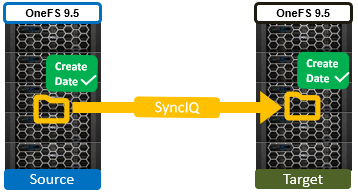
The primary consideration for the new create date functionality is that it requires both source and target clusters in a replication set to be running OneFS 9.5 or later.
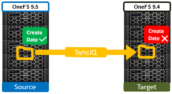
If either the source or the target is running pre-9.5 code, this time field retains its old behavior of being set to the time of replication (actual file creation) rather than the correct value associated with the source file.
In OneFS 9.5 and later releases, create date timestamping works exactly the same way as SyncIQ replication of other metadata (such as “mtime”, etc), occurring automatically as part of every file replication. Plus, no additional configuration is necessary beyond upgrading both clusters to OneFS 9.5 or later.
One other significant thing to note about this feature is that SyncIQ is changelist-based, using OneFS snapshots under the hood for its checkpointing and delta comparisons.. This means that, if a replication relationship has been configured prior to OneFS 9.5 or later upgrade, the source cluster will have valid birthtime data, but the target’s birthtime data will reflect the local creation time of the files it’s copied.
Note: that, upon upgrading both sides to OneFS 9.5 or later and running a SyncIQ job, nothing will change. This is because SyncIQ will perform its snapshot comparison, determine that no changes were made to the dataset, and so will not perform any replication work. However, if a source file is “touched” so that it’s mtime is changed (or any other action performed that will cause a copy-on-write, or CoW) that will cause the file to show up in the snapshot diff and therefore be replicated. As part of replicating that file, the correct birth time will be written on the target.
Note: that a full replication (re)sync does not get triggered as a result of upgrading a replication cluster pair to OneFS 9.5 or later and thereby enabling this functionality. Instead, any create date timestamp resolution happens opportunistically and in the background as files gets touched or modified - and thereby replicated. Be aware that ‘touching’ a file does change its modification time, in addition to updating the create date, which may be undesirable.
Author: Nick Trimbee

Securing PowerScale OneFS SyncIQ
Tue, 16 Apr 2024 17:55:56 -0000
|Read Time: 0 minutes
In the data replication world, ensuring your PowerScale clusters' security is paramount. SyncIQ, a powerful data replication tool, requires encryption to prevent unauthorized access.
Concerns about unauthorized replication
A cluster might inadvertently become the target of numerous replication policies, potentially overwhelming its resources. There’s also the risk of an administrator mistakenly specifying the wrong cluster as the replication target.
Best practices for security
To secure your PowerScale cluster, Dell recommends enabling SyncIQ encryption as per Dell Security Advisory DSA-2020-039: Dell EMC Isilon OneFS Security Update for a SyncIQ Vulnerability | Dell US. This feature, introduced in OneFS 8.2, prevents man-in-the-middle attacks and addresses other security concerns.
Encryption in new and upgraded clusters
SyncIQ is disabled by default for new clusters running OneFS 9.1. When SyncIQ is enabled, a global encryption flag requires all SyncIQ policies to be encrypted. This flag is also set for clusters upgraded to OneFS 9.1, unless there’s an existing SyncIQ policy without encryption.
Alternative measures
For clusters running versions earlier than OneFS 8.2, configuring a SyncIQ pre-shared key (PSK) offers protection against unauthorized replication policies.
By following these security measures, administrators can ensure that their PowerScale clusters are safeguarded against unauthorized access and maintain the integrity and confidentiality of their data.
SyncIQ encryption: securing data in transit
Securing information as it moves between systems is paramount in the data-driven world. Dell PowerScale OneFS release 8.2 has brought a game-changing feature to the table: end-to-end encryption for SyncIQ data replication. This ensures that data is not only protected while at rest but also as it traverses the network between clusters.
Why encryption matters
Data breaches can be catastrophic, and because data replication involves moving large volumes of sensitive information, encryption acts as a critical shield. With SyncIQ’s encryption, organizations can enforce a global setting that mandates encryption across all SyncIQ policies, to add an extra layer of security.
Test before you implement
It’s crucial to test SyncIQ encryption in a lab environment before deploying it in production. Although encryption introduces minimal overhead, its impact on workflow can vary based on several factors, such as network bandwidth and cluster resources.
Technical underpinnings
SyncIQ encryption is powered by X.509 certificates, TLS version 1.2, and OpenSSL version 1.0.2o6. These certificates are meticulously managed within the cluster’s certificate stores, ensuring a robust and secure data replication process.
Remember, this is just the beginning of a comprehensive guide about SyncIQ encryption. Stay tuned for more insights about configuration steps and best practices for securing your data with Dell PowerScale’s innovative solutions.
Configuration
Configuring SyncIQ encryption requires a supported OneFS release, certificates, and finally, the OneFS configuration. Before enabling SyncIQ encryption in production, test it in a lab environment that mimics the production setup. Measure the impact on transmission overhead by considering network bandwidth, cluster resources, workflow, and policy configuration.
Here’s a high level summary of the configuration steps:
- Ensure compatibility:
- Ensure that the source and target clusters are running OneFS 8.2 or later.
- Upgrade and commit both clusters to OneFS release 8.2 or later.
- Create X.509 certificates:
- Create X.509 certificates for the source and target clusters using publicly available tools.
- The certificate creation process results in the following components:
- Certificate Authority (CA) certificate
- Source certificate and private key
- Target certificate and private key
Note: Some certificate authorities may not generate the public and private key pairs. In that case, manually generate a Certificate Signing Request (CSR) and obtain signed certificates.
3. Transfer certificates to clusters:
- Transfer the certificates to each cluster.
4. Activate each certificate as follows:
- Add the source cluster certificate under Data Protection > SyncIQ > Certificates.
- Add the target server certificate under Data Protection > SyncIQ > Settings.
- Add the Certificate Authority under Access > TLS Certificates and select Import Authority.
5. Enforce encryption:
- Each cluster stores its certificate and its peer’s certificate.
- The source cluster must store the target cluster’s certificate, and vice versa.
- Storing the peer’s certificate creates a list of approved clusters for data replication.
By following these steps, you can secure your data in transit between PowerScale clusters using SyncIQ encryption. Remember to customize the certificates and settings according to your specific environment and requirements.
For more detailed information about configuring SyncIQ encryption, see SyncIQ encryption | Dell PowerScale SyncIQ: Architecture, Configuration, and Considerations | Dell Technologies Info Hub.
SyncIQ pre-shared key
A SyncIQ pre-shared key (PSK) is configured solely on the target cluster to restrict policies from source clusters without the PSK.
Use Cases: This is recommended for environments without SyncIQ encryption, such as clusters pre-OneFS 8.2 or due to other factors.
SmartLock Compliance: Not supported by SmartLock Compliance mode clusters; upgrading and configuring SyncIQ encryption is advised.
Policy Update: After updating source cluster policies with the PSK, no further configuration is needed. Use the isi sync policies view command to verify.
Remember, configuring the PSK will cause all replicating jobs to the target cluster to fail, so ensure that all SyncIQ jobs are complete or canceled before proceeding.
For more detailed information about configuring a SyncIQ pre-shared key, see SyncIQ pre-shared key | Dell PowerScale SyncIQ: Architecture, Configuration, and Considerations | Dell Technologies Info Hub.
Resources
- SyncIQ encryption | Dell PowerScale SyncIQ: Architecture, Configuration, and Considerations | Dell Technologies Info Hub
- SyncIQ pre-shared key | Dell PowerScale SyncIQ: Architecture, Configuration, and Considerations | Dell Technologies Info Hub
Author: Aqib Kazi, Senior Principal Engineering Technologist

PowerScale OneFS 9.8
Tue, 09 Apr 2024 14:00:00 -0000
|Read Time: 0 minutes
It’s launch season here at Dell Technologies, and PowerScale is already scaling up spring with the innovative OneFS 9.8 release which shipped today, 9th April 2024. This new 9.8 release has something for everyone, introducing PowerScale innovations in cloud, performance, serviceability, and ease of use.
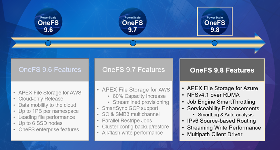 Figure 1. OneFS 9.8 release features
APEX File Storage for Azure
After the debut of APEX File Storage for AWS last year, OneFS 9.8 amplifies PowerScale’s presence in the public cloud by introducing APEX File Storage for Azure.
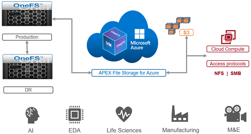 Figure 2. OneFS 9.8 APEX File Storage for Azure
In addition to providing the same OneFS software platform on-prem and in the cloud as well as customer-managed for full control, APEX File Storage for Azure in OneFS 9.8 provides linear capacity and performance scaling from four to eighteen SSD nodes and up to 3PB per cluster, making it a solid fit for AI, ML, and analytics applications, as well as traditional file shares and home directories and vertical workloads like M&E, healthcare, life sciences, and financial services.
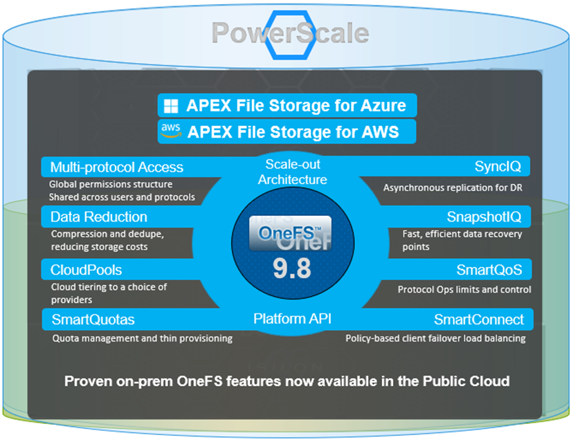 Figure 3. Dell PowerScale scale-out architecture
PowerScale’s scale-out architecture can be deployed on customer-managed AWS and Azure infrastructure, providing the capacity and performance needed to run a variety of unstructured workflows in the public cloud.
Once in the cloud, existing PowerScale investments can be further leveraged by accessing and orchestrating your data through the platform's multi-protocol access and APIs.
This includes the common OneFS control plane (CLI, WebUI, and platform API) and the same enterprise features, such as Multi-protocol, SnapshotIQ, SmartQuotas, Identity management, and so on.
Simplicity and efficiency
OneFS 9.8 SmartThrottling is an automated impact control mechanism for the job engine, allowing the cluster to automatically throttle job resource consumption if it exceeds pre-defined thresholds in order to prioritize client workloads.
OneFS 9.8 also delivers automatic on-cluster core file analysis, and SmartLog provides an efficient, granular log file gathering and transmission framework. Both of these new features help dramatically accelerate the ease and time to resolution of cluster issues.
Performance
OneFS 9.8 also adds support for Remote Direct Memory Access (RDMA) over NFS 4.1 support for applications and clients. This allows for substantially higher throughput performance – especially in the case of single-connection and read-intensive workloads such as machine learning and generative AI model training – while also reducing both cluster and client CPU utilization and provides the foundation for interoperability with NVIDIA’s GPUDirect.
RDMA over NFSv4.1 in OneFS 9.8 leverages the ROCEv2 network protocol. OneFS CLI and WebUI configuration options include global enablement and IP pool configuration, filtering, and verification of RoCEv2 capable network interfaces. NFS over RDMA is available on all PowerScale platforms containing Mellanox ConnectX network adapters on the front end and with a choice of 25, 40, or 100 Gigabit Ethernet connectivity. The OneFS user interface helps easily identify which of a cluster’s NICs support RDMA.
Under the hood, OneFS 9.8 introduces efficiencies such as lock sharding and parallel thread handling, delivering a substantial performance boost for streaming write-heavy workloads such as generative AI inferencing and model training. Performance scales linearly as compute is increased, keeping GPUs busy and allowing PowerScale to easily support AI and ML workflows both small and large. OneFS 9.8 also includes infrastructure support for future node hardware platform generations.
Multipath Client Driver
The addition of a new Multipath Client Driver helps expand PowerScale’s role in Dell Technologies’ strategic collaboration with NVIDIA, delivering the first and only end-to-end large scale AI system. This is based on the PowerScale F710 platform in conjunction with PowerEdge XE9680 GPU servers and NVIDIA’s Spectrum-X Ethernet switching platform to optimize performance and throughput at scale.
In summary, OneFS 9.8 brings the following new features to the Dell PowerScale ecosystem:
Feature | Info |
Cloud |
|
Simplicity |
|
Performance |
|
Serviceability |
|
We’ll be taking a deeper look at this new functionality in blog articles over the course of the next few weeks.
Meanwhile, the new OneFS 9.8 code is available on the Dell Online Support site, both as an upgrade and reimage file, allowing installation and upgrade of this new release.
Author: Nick Trimbee

Unveiling APEX File Storage for Microsoft Azure – Running PowerScale OneFS on Azure
Tue, 09 Apr 2024 20:30:02 -0000
|Read Time: 0 minutes
Overview
PowerScale OneFS 9.8 now brings a new offering in Azure — APEX File Storage for Microsoft Azure! It is a software-defined cloud file storage service that provides high-performance, flexible, secure, and scalable file storage for Microsoft Azure environments. It is also a fully customer managed service that is designed to meet the needs of enterprise-scale file workloads running on Azure. This offer joins another native cloud solution that was released last year - APEX File Storage for AWS, for more information, refer to the link: https://www.dell.com/en-us/dt/apex/storage/public-cloud/file.htm?hve=explore+file
Benefits of running OneFS in Cloud
APEX File Storage for Microsoft Azure brings the OneFS distributed file system software into the public cloud, allowing users to have the same management experience in the cloud as with their on-premises PowerScale appliance.
With APEX File Storage for Microsoft Azure, you can easily deploy and manage file storage on Azure. The service provides a scalable and elastic storage infrastructure that can grow, according to your actual business needs.
Some of the key features and benefits of APEX File Storage for Microsoft Azure include:
- Scale-out: APEX File Storage for Microsoft Azure is powered by the Dell PowerScale OneFS distributed file system. You can start with a small OneFS cluster (minimal 4 nodes) and then expand it incrementally as your data storage requirements grow up to 5.6 PiB in cluster capacity with a single namespace (maximum 18 nodes). This large capacity helps support the most demanding, data intensive workloads such as AI.
- Data management: APEX File Storage for Microsoft Azure provides powerful data management capabilities such as: snapshot, data replication, and backup and restore. Because OneFS features are the same in the cloud as they are in on-premises, organizations can simplify operations and reduce management complexity with a consistent user experience.
- Simplified journey to hybrid cloud: More and more organizations operate in a hybrid cloud environment, where they need to move data between on-premises and cloud-based environments. APEX File Storage for Microsoft Azure can help you bridge this gap by facilitating seamless data mobility between on-premises and the cloud with native replication and by providing a consistent data management platform across both environments. Once in the cloud, customers can take advantage of enterprise-class OneFS features such as: multi-protocol support, CloudPools, data reduction, security, and snapshots, to run their workloads in the same way as they do on-premises.
- Data resilience: Ensuring data resilience is critical for businesses to maintain continuity and to safeguard information. APEX File Storage for Microsoft Azure implements erasure coding techniques. This advanced approach optimizes storage efficiency and enhances fault tolerance, enabling the cluster to withstand multiple node failures. By spreading nodes across different racks using Azure availability set, the cluster ensures that data accessibility is maintained in the event of a rack failure.
- High performance: APEX File Storage for Microsoft Azure delivers high-performance file storage with low-latency access to data, ensuring that you can access data quickly and efficiently. Compared to Azure NetApp Files, Dell APEX File Storage for Microsoft Azure enables: about 6x greater cluster performance, up to 11x larger namespace, up to 23x more snapshots per volume, 2x higher cluster resiliency, and an easier and more robust cluster expansion.
- Proactive support: With a 97% customer satisfaction rate, Dell Support Services provides highly trained experts around the clock and around the globe to address your OneFS needs, minimize disruptions, and help you maintain a high level of productivity and outcomes.
Architecture
APEX File Storage for Microsoft Azure is a software-defined cloud file storage service that combines the power of OneFS distributed file system with the flexibility and scalability of cloud infrastructure. It is a fully customer-managed service that is designed to meet the needs of enterprise-scale file workloads running on Azure.
The architecture of APEX File Storage for Microsoft Azure is built on the OneFS distributed file system. This architecture uses multiple cluster nodes to establish a single global namespace. Each cluster node operates as an instance of the OneFS software, running on an Azure VM to deliver storage capacity and compute resources. It is worth noting that the network bandwidth limit at the Azure VM level is shared between the cluster internal network and the external network.
APEX File Storage for Microsoft Azure uses cloud-native technologies and leverages the elasticity of cloud infrastructure, so that you can easily scale the storage infrastructure as your business requirements grow. APEX File Storage for Microsoft Azure can dynamically scale storage capacity and performance to meet changing demands. It is able to add additional cluster nodes without disruption enabling the storage infrastructure to scale in a more cost-effective and efficient manner. To guarantee the durability and resiliency of data, APEX File Storage for Microsoft Azure distributes data across multiple nodes within the cluster. It also uses advanced data protection techniques such as erasure coding and it provides features such as SyncIQ to ensure that data is available. Even in the event of one or more node failures, the data remains accessible from the remaining cluster nodes.
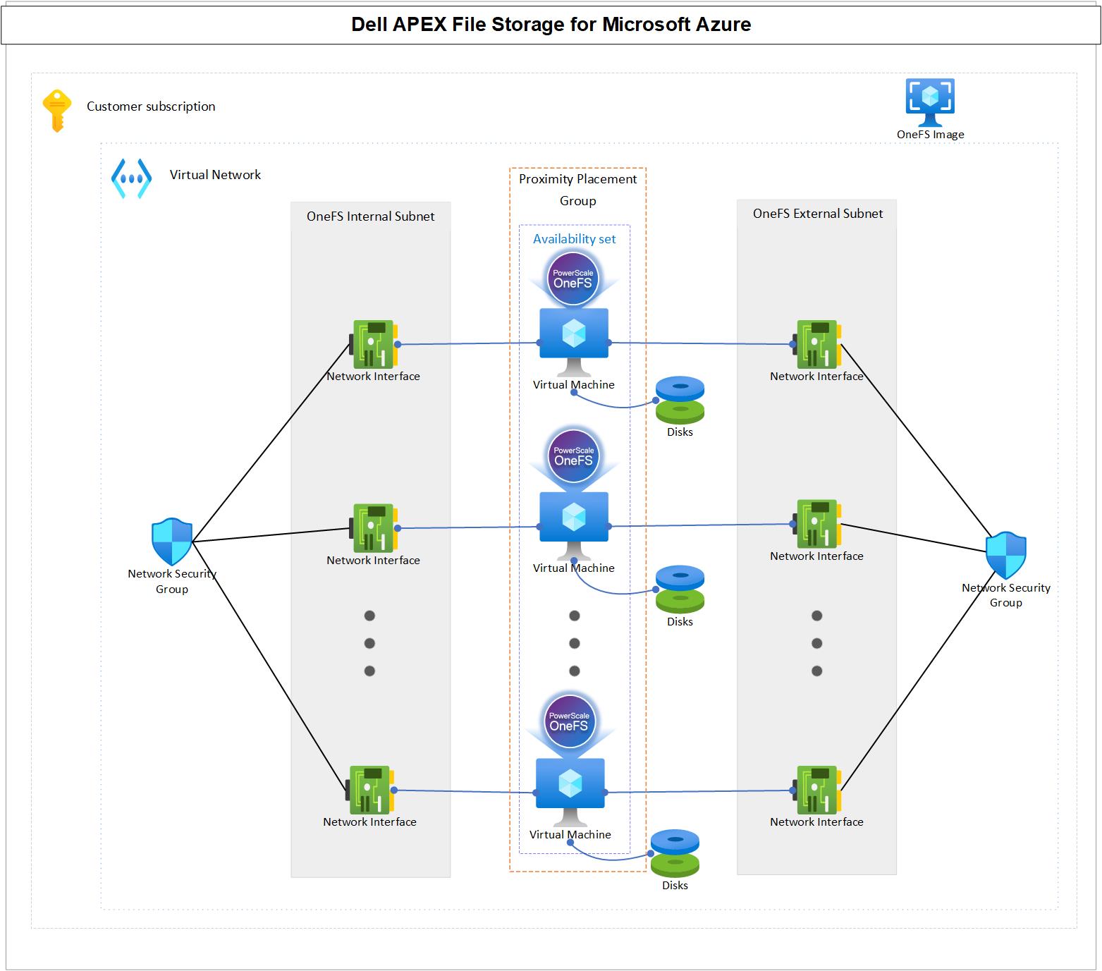
Availability set and proximity placement group: APEX File Storage for Microsoft Azure is designed to run in an availability set, and the availability set is associated with a dedicated proximity placement group. In this way, APEX File Storage for Microsoft Azure can have better reliability by ensuring more consistent, lower latency on the cluster backend network.
Virtual network: APEX File Storage for Microsoft Azure requires an Azure virtual network to provide network connectivity.
- OneFS cluster internal subnet: The cluster nodes communicate with each other through the internal subnet. The internal subnet must be isolated from VMs that are not in the cluster. Therefore, a dedicated subnet is required for the internal network interfaces of cluster nodes that do not share the internal subnets with other Azure VMs.
- OneFS cluster external subnet: The cluster nodes communicate with clients through the external subnet by using different protocols, such as NFS, SMB, and S3.
- OneFS cluster internal network interfaces: Network interfaces are in the internal subnet.
- OneFS cluster external network interfaces: Network interfaces are in the external subnet.
- Network security group: The network security group applies to the cluster network interfaces, which allows/denies specific traffic to OneFS cluster.
- Azure VMs: These VMs serve as cluster nodes running the OneFS file system, backed by Azure managed disks. Each node within the cluster is strategically placed in an availability set and a proximity placement group. This configuration ensures that all nodes reside in separate fault domains, enhancing reliability, and it brings them physically closer together to enable lower network latency between cluster nodes. See the Azure availability sets overview and Azure proximity placement groups documentation for more details.
Overall, APEX File Storage for Microsoft Azure offers a powerful and flexible scale-out file storage solution that can help you improve data management, optimize costs, scalability, and security in a cloud-based environment.
Supported cluster configurations
Table 1 shows the supported configuration for APEX File Storage on Azure. It provides you the flexibility to choose different cluster size, various Azure VM size/SKU and so many Azure disk options to meeting your business requirements. For the detailed explanation of these configurations, refer to https://infohub.delltechnologies.com/en-US/t/apex-file-storage-for-microsoft-azure-deployment-guide.
- Supported configuration for a single cluster
Configuration items | Supported options |
Cluster size | 4 to 18 nodes |
Azure VM size/SKU | All nodes in a cluster must use the same VM size/SKU. The supported VM sizes are:
|
Azure managed disk type | All nodes in a cluster muse use the same disk type. The supported disk types are:
Note: Premium SSDs are only supported with Ddsv5-series and Edsv5-series |
Azure managed disk size | All nodes in a cluster muse use the same disk size. The supported disk sizes are:
|
Disk count per node | All nodes in a cluster muse use the same disk count. The supported disk counts are:
|
Cluster raw capacity | Minimum: 10 TiB, maximum: 5760 TiB |
Cluster protection level | Default is +2n. Also supports +2d:1n with additional capacity restrictions. |
Support Regions
APEX File Storage for Microsoft Azure is globally available. For the detailed regions, refer to https://infohub.delltechnologies.com/en-US/t/apex-file-storage-for-microsoft-azure-deployment-guide.
Performance
Compared to Azure NetApp Files, Dell APEX File Storage for Microsoft Azure enables about 6x greater cluster performance, up to 11x larger namespace, up to 23x more snapshots per volume, 2x higher cluster resiliency, and easier and more robust cluster expansion.
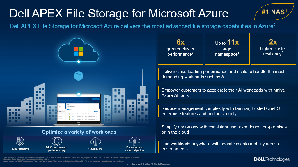
Besides that, I will show you an example of how sequential read and sequential write performance can be linearly scaled out from 4 nodes to 18 nodes to make sure it meets your business requirements.
This is what we have set up:
We are using Azure Standard D48ds_v5 VM type and we scale from 10 nodes to 14 nodes and in the end to 18 nodes for testing purposes. With each deployment we kept all the other factors the same, we maintained 12 P40 Azure premium SSDs for data disks in each node. The following table displays the configuration:
Node type | Node count | Data disk type | Data disk count |
10 | P40 | 12 | |
14 | P40 | 12 | |
18 | P40 | 12 |
The diagram below demonstrates how read performance increases when we scale out our APEX File Storage for Microsoft Azure. You can see a clear positive trend starting from 10 nodes to 18 nodes. The same conclusion also applies with write performance.
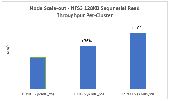
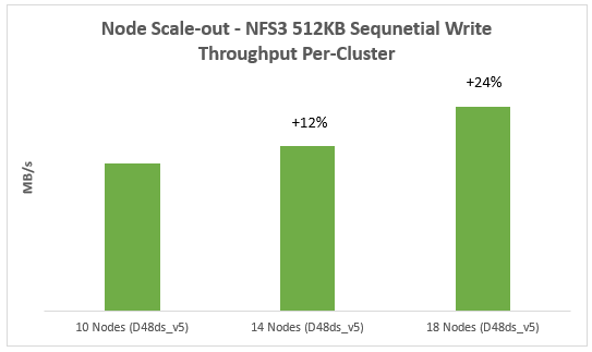
Another example is that you can also scale-up the overall performance of an APEX File Storage for Microsoft Azure by choosing a more powerful Azure VM size/SKU:
In this example, we tested the following Azure VM size/SKU with the same node number (4) and disk number per node (12):
- D32ds_v5
- D48ds_v5
- D64ds_v5
- E104ids_v5
From the results, we can easily find that with the scale-up of Azure VM size/SKU, both read and write performance increase:
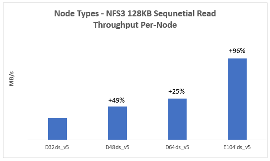

For more details on the performance results and best practices, refer to the following whitepaper https://infohub.delltechnologies.com/en-US/t/introduction-to-apex-file-storage-for-azure-1/.
Resources
https://infohub.delltechnologies.com/en-US/t/apex-file-storage-for-microsoft-azure-deployment-guide
https://infohub.delltechnologies.com/en-US/t/introduction-to-apex-file-storage-for-azure-1/
https://www.dell.com/en-us/blog/ai-anywhere-with-apex-file-storage-for-microsoft-azure/
Authors:
Vincent Shen, Lieven Lin, and Jason He

Optimizing AI: Meeting Unstructured Storage Demands Efficiently
Thu, 21 Mar 2024 14:46:23 -0000
|Read Time: 0 minutes
The surge in artificial intelligence (AI) and machine learning (ML) technologies has sparked a revolution across industries, pushing the boundaries of what's possible. However, this innovation comes with its own set of challenges, particularly when it comes to storage. The heart of AI's potential lies in its ability to process and learn from vast amounts of data, most of which is unstructured. This has placed unprecedented demands on storage solutions, becoming a critical bottleneck for advancing AI technologies.
Navigating the complex landscape of unstructured data storage is no small feat. Traditional storage systems struggle to keep up with the scale and flexibility required by AI workloads. Enterprises find themselves at a crossroads, seeking solutions that can provide scalable, affordable, and fault-tolerant storage. The quest for such a platform is not just about meeting current needs but also paving the way for the future of AI-driven innovation.
The current state of ML and AI
The evolution of ML and AI technologies has reshaped industries far and wide, setting new expectations for data processing and analysis capabilities. These advancements are directly tied to an organization's capacity to handle vast volumes of unstructured data, a domain where traditional storage solutions are being outpaced.
ML and AI applications demand unprecedented levels of data ingestion and computational power, necessitating scalable and flexible storage solutions. Traditional storage systems—while useful for conventional data storage needs—grapple with scalability issues, particularly when faced with the immense file quantities AI and ML workloads generate.
Although traditional object storage methods are capable of managing data as objects within a pool, they fall short when meeting the agility and accessibility requirements essential for AI and ML processes. These storage models struggle with scalability and facilitating the rapid access and processing of data crucial for deep learning and AI algorithms.
The dire necessity of a new kind of storage solution is evident as the current infrastructure is unable to cope with the silos of unstructured data. These silos make it challenging to access, process, and unify data sources, which in turn cripples the effectiveness of AI and ML projects. Furthermore, the maximum storage capacity of traditional storage, tethering at tens of terabytes, is insufficient for the needs of AI-driven initiatives which often require petabytes of data to train sophisticated models.
As ML and AI continue to advance, the quest for a storage solution that can support the growing demands of these technologies remains pivotal. The industry is in dire need of systems that provide ample storage and ensure the flexibility, reliability, and performance efficiency necessary to propel AI and ML into their next phase of innovation.
Understanding unstructured storage demands for AI
The advent of AI and ML has brought unprecedented advancements across industries, enhancing efficiency, accuracy, and the ability to manage and process large datasets. However, the core of these technologies relies on the capability to store, access, and analyze unstructured data efficiently. Understanding the storage demands essential for AI applications is crucial for businesses looking to harness the full power of AI technology.
High throughput and low latency
For AI and ML applications, time is of the essence. The ability to process data at high speeds with high throughput and access it with minimal delay and low latency are non-negotiable requirements. These applications often involve complex computations performed on vast datasets, necessitating quick access to data to maintain a seamless process. For instance, in real-time AI applications such as voice recognition or instant fraud detection, any delay in data processing can critically impact performance and accuracy. Therefore, storage solutions must be designed to accommodate these needs, delivering data as swiftly as possible to the application layer.
Scalability and flexibility
As AI models evolve and the volume of data increases, the need for scalability in storage solutions becomes paramount. The storage architecture must accommodate growth without compromising on performance or efficiency. This is where the flexibility of the storage solutions comes into play. An ideal storage system for AI would scale in capacity and performance, adapting to the changing demands of AI applications over time. Combining the best of on-premises and cloud storage, hybrid storage solutions offer a viable path to achieving this scalability and flexibility. They enable businesses to leverage the high performance of on-premise solutions and the scalability and cost-efficiency of cloud storage, ensuring the storage infrastructure can grow with the AI application needs.
Data durability and availability
Ensuring the durability and availability of data is critical for AI systems. Data is the backbone of any AI application, and its loss or unavailability can lead to significant setbacks in development and performance. Storage solutions must, therefore, provide robust data protection mechanisms and redundancies to safeguard against data loss. Additionally, high availability is essential to ensure that data is always accessible when needed, particularly for AI applications that require continuous operation. Implementing a storage system with built-in redundancy, failover capabilities, and disaster recovery plans is essential to maintain continuous data availability and integrity.
In the context of AI where data is continually ingested, processed, and analyzed, the demands on storage solutions are unique and challenging. Key considerations include maintaining high throughput and low latency for real-time processing, establishing scalability and flexibility to adapt to growing data volumes, and ensuring data durability and availability to support continuous operation. Addressing these demands is critical for businesses aiming to leverage AI technologies effectively, paving the way for innovation and success in the digital era.
What needs to be stored for AI?
The evolution of AI and its underlying models depends significantly on various types of data and artifacts generated and used throughout its lifecycle. Understanding what needs to be stored is crucial for ensuring the efficiency and effectiveness of AI applications.
Raw data
Raw data forms the foundation of AI training. It's the unmodified, unprocessed information gathered from diverse sources. For AI models, this data can be in the form of text, images, audio, video, or sensor readings. Storing vast amounts of raw data is essential as it provides the primary material for model training and the initial step toward generating actionable insights.
Preprocessed data
Once raw data is collected, it undergoes preprocessing to transform it into a more suitable format for training AI models. This process includes cleaning, normalization, and transformation. As a refined version of raw data, preprocessed data needs to be stored efficiently to streamline further processing steps, saving time and computational resources.
Training datasets
Training datasets are a selection of preprocessed data used to teach AI models how to make predictions or perform tasks. These datasets must be diverse and comprehensive, representing real-world scenarios accurately. Storing these datasets allows AI models to learn and adapt to the complexities of the tasks they are designed to perform.
Validation and test datasets
Validation and test datasets are critical for evaluating an AI model's performance. These datasets are separate from the training data and are used to tune the model's parameters and test its generalizability to new, unseen data. Proper storage of these datasets ensures that models are both accurate and reliable.
Model parameters and weights
An AI model learns to make decisions through its parameters and weights. These elements are fine-tuned during training and crucial for the model's decision-making processes. Storing these parameters and weights allows models to be reused, updated, or refined without retraining from scratch.
Model architecture
The architecture of an AI model defines its structure, including the arrangement of layers and the connections between them. Storing the model architecture is essential for understanding how the model processes data and for replicating or scaling the model in future projects.
Hyperparameters
Hyperparameters are the configuration settings used to optimize model performance. Unlike parameters, hyperparameters are not learned from the data but set prior to the training process. Storing hyperparameter values is necessary for model replication and comparison of model performance across different configurations.
Feature engineering artifacts
Feature engineering involves creating new input features from the existing data to improve model performance. The artifacts from this process, including the newly created features and the logic used to generate them, need to be stored. This ensures consistency and reproducibility in model training and deployment.
Results and metrics
The results and metrics obtained from model training, validation, and testing provide insights into model performance and effectiveness. Storing these results allows for continuous monitoring, comparison, and improvement of AI models over time.
Inference data
Inference data refers to new, unseen data that the model processes to make predictions or decisions after training. Storing inference data is key for analyzing the model's real-world application and performance and making necessary adjustments based on feedback.
Embeddings
Embeddings are dense representations of high-dimensional data in lower-dimensional spaces. They play a crucial role in processing textual data, images, and more. Storing embeddings allows for more efficient computation and retrieval of similar items, enhancing model performance in recommendation systems and natural language processing tasks.
Code and scripts
The code and scripts used to create, train, and deploy AI models are essential for understanding and replicating the entire AI process. Storing this information ensures that models can be retrained, refined, or debugged as necessary.
Documentation and metadata
Documentation and metadata provide context, guidelines, and specifics about the AI model, including its purpose, design decisions, and operating conditions. Proper storage of this information supports ethical AI practices, model interpretability, and compliance with regulatory standards.
Challenges of unstructured data in AI
In the realm of AI, handling unstructured data presents a unique set of challenges that must be navigated carefully to harness its full potential. As AI systems strive to mimic human understanding, they face the intricate task of processing and deriving meaningful insights from data that lacks a predefined format. This section delves into the core challenges associated with unstructured data in AI, primarily focusing on data variety, volume, and velocity.
Data variety
Data variety refers to the myriad types of unstructured data that AI systems are expected to process, ranging from texts and emails to images, videos, and audio files. Each data type possesses its unique characteristics and demands specific preprocessing techniques to be effectively analyzed by AI models.
- Richer Insights but Complicated Processing: While the diverse data types can provide richer insights and enhance model accuracy, they significantly complicate the data preprocessing phase. AI tools must be equipped with sophisticated algorithms to identify, interpret, and normalize various data formats.
- Innovative AI Applications: The advantage of mastering data variety lies in the development of innovative AI applications. By handling unstructured data from different domains, AI can contribute to advancements in natural language processing, computer vision, and beyond.
Data volume
The sheer volume of unstructured data generated daily is staggering. As digital interactions increase, so does the amount of data that AI systems need to analyze.
- Scalability Challenges: The exponential growth in data volume poses scalability challenges for AI systems. Storage solutions must not only accommodate current data needs but also be flexible enough to scale with future demands.
- Efficient Data Processing: AI must leverage parallel processing and cloud storage options to keep up with the volume. Systems designed for high-throughput data analysis enable quicker insights, which are essential for timely decision-making and maintaining relevance in a rapidly evolving digital landscape.
Data velocity
Data velocity refers to the speed at which new data is generated and the pace at which it needs to be processed to remain actionable. In the age of real-time analytics and instant customer feedback, high data velocity is both an opportunity and a challenge for AI.
- Real-Time Processing Needs: AI systems are increasingly required to process information in real-time or near-real-time to provide timely insights. This necessitates robust computational infrastructure and efficient data streaming technologies.
- Constant Adaptation: The dynamic nature of unstructured data, coupled with its high velocity, demands that AI systems constantly adapt and learn from new information. Maintaining accuracy and relevance in fast-moving data environments is critical for effective AI performance.
In addressing these challenges, AI and ML technologies are continually evolving, developing more sophisticated systems capable of handling the complexity of unstructured data. The key to unlocking the value hidden within this data lies in innovative approaches to data management where flexibility, scalability, and speed are paramount.
Strategies to manage unstructured data in AI
The explosion of unstructured data poses unique challenges for AI applications. Organizations must adopt effective data management strategies to harness the full potential of AI technologies. In this section, we delve into key strategies like data classification and tagging and the use of PowerScale clusters to efficiently manage unstructured data in AI.
Data classification and tagging
Data classification and tagging are foundational steps in organizing unstructured data and making it more accessible for AI applications. This process involves identifying the content and context of data and assigning relevant tags or labels, which is crucial for enhancing data discoverability and usability in AI systems.
- Automated tagging tools can significantly reduce the manual effort required to label data, employing AI algorithms to understand the content and context automatically.
- Custom metadata tags allow for the creation of a rich set of file classification information. This not only aids in the classification phase but also simplifies later iterations and workflow automation.
- Effective data classification enhances data security by accurately categorizing sensitive or regulated information, enabling compliance with data protection regulations.
Implementing these strategies for managing unstructured data prepares organizations for the challenges of today's data landscape and positions them to capitalize on the opportunities presented by AI technologies. By prioritizing data classification and leveraging solutions like PowerScale clusters, businesses can build a strong foundation for AI-driven innovation.

Best practices for implementing AI storage solutions
Implementing the right AI storage solutions is crucial for businesses seeking to harness the power of artificial intelligence. With the explosive growth of unstructured data, adhering to best practices that optimize performance, scalability, and cost is imperative. This section delves into key practices to ensure your AI storage infrastructure meets the demands of modern AI workloads.
Assess workload requirements
Before diving into storage solutions, one must thoroughly assess AI workload requirements. Understanding the specific needs of your AI applications—such as the volume of data, the necessity for high throughput/low latency, and the scalability and availability requirements—is fundamental. This step ensures you select the most suitable storage solution that meets your application's needs.
AI workloads are diverse, with each having unique demands on storage infrastructure. For instance, training a machine learning model could require rapid access to vast amounts of data, whereas inference workloads may prioritize low latency. An accurate assessment leads to an optimized infrastructure, ensuring that storage solutions are neither overprovisioned nor underperforming, thereby supporting AI applications efficiently and cost-effectively.
Leverage PowerScale
For managing large volumes and varieties of unstructured data, leveraging PowerScale nodes offers a scalable and efficient solution. PowerScale nodes are designed to handle the complexities of AI and machine learning workloads, offering optimized performance, scalability, and data mobility. These clusters allow organizations to store and process vast amounts of data efficiently for a range of AI use cases due to the following:
- Scalability is a key feature, with PowerScale clusters capable of growing with the organization's data needs. They support massive capacities, allowing businesses to store petabytes of data seamlessly.
- Performance is optimized for the demanding workloads of AI applications with the ability to process large volumes of data at high speeds, reducing the time for data analyses and model training.
- Data mobility within PowerScale clusters on-premise and in the cloud ensures that data can be accessed when and where needed, supporting various AI and machine learning use cases across different environments.
PowerScale clusters allow businesses to start small and grow capacity as needed, ensuring that storage infrastructure can scale alongside AI initiatives without compromising on performance. The ability to handle multiple data types and protocols within a single storage infrastructure simplifies management and reduces operational costs, making PowerScale nodes an ideal choice for dynamic AI environments.
Utilize PowerScale OneFS 9.7.0.0
PowerScale OneFS 9.7.0.0 is the latest version of the Dell PowerScale operating system for scale-out network-attached storage (NAS). OneFS 9.7.0.0 introduces several enhancements in data security, performance, cloud integration, and usability.
OneFS 9.7.0.0 extends and simplifies the PowerScale offering in the public cloud, providing more features across various instance types and regions. Some of the key features in OneFS 9.7.0.0 include:
- Cloud Innovations: Extends cloud capabilities and features, building upon the debut of APEX File Storage for AWS
- Performance Enhancements: Enhancements to overall system performance
- Security Enhancements: Enhancements to data security features
- Usability Improvements: Enhancements to make managing and using PowerScale easier
Employ PowerScale F210 and F710
PowerScale, through its continuous innovation, extends into the AI era by introducing the next generation of PowerEdge-based nodes: the PowerScale F210 and F710. These new all-flash nodes leverage the Dell PowerEdge R660 from the PowerEdge platform, unlocking enhanced performance capabilities.
On the software front, both the F210 and F710 nodes benefit from significant performance improvements in PowerScale OneFS 9.7. These nodes effectively address the most demanding workloads by combining hardware and software innovations. The PowerScale F210 and F710 nodes represent a powerful combination of hardware and software advancements, making them well-suited for a wide range of workloads. For more information on the F210 and F710, see PowerScale All-Flash F210 and F710 | Dell Technologies Info Hub.
Ensure data security and compliance
Given the sensitivity of the data used in AI applications, robust security measures are paramount. Businesses must implement comprehensive security strategies that include encryption, access controls, and adherence to data protection regulations. Safeguarding data protects sensitive information and reinforces customer trust and corporate reputation.
Compliance with data protection laws and regulations is critical to AI storage solutions. As regulations can vary significantly across regions and industries, understanding and adhering to these requirements is essential to avoid significant fines and legal challenges. By prioritizing data security and compliance, organizations can mitigate risks associated with data breaches and non-compliance.
Monitor and optimize
Continuous storage environment monitoring and optimization are essential for maintaining high performance and efficiency. Monitoring tools can provide insights into usage patterns, performance bottlenecks, and potential security threats, enabling proactive management of the storage infrastructure.
Regular optimization efforts can help fine-tune storage performance, ensuring that the infrastructure remains aligned with the evolving needs of AI applications. Optimization might involve adjusting storage policies, reallocating resources, or upgrading hardware to improve efficiency, reduce costs, and ensure that storage solutions continue to effectively meet the demands of AI workloads.
By following these best practices, businesses can build and maintain a storage infrastructure that supports their current AI applications and is poised for future growth and innovation.
Conclusion
Navigating the complexities of unstructured storage demands for AI is no small feat. Yet, by adhering to the outlined best practices, businesses stand to benefit greatly. The foundational steps include assessing workload requirements, selecting the right storage solutions, and implementing robust security measures. Furthermore, integrating PowerScale nodes and a commitment to continuous monitoring and optimization are key to sustaining high performance and efficiency. As the landscape of AI continues to evolve, these practices will not only support current applications but also pave the way for future growth and innovation. In the dynamic world of AI, staying ahead means being prepared, and these strategies offer a roadmap to success.
Frequently asked questions
How big are AI data centers?
Data centers catering to AI, such as those by Amazon and Google, are immense, comparable to the scale of football stadiums.
How does AI process unstructured data?
AI processes unstructured data including images, documents, audio, video, and text by extracting and organizing information. This transformation turns unstructured data into actionable insights, propelling business process automation and supporting AI applications.
How much storage does an AI need?
AI applications, especially those involving extensive data sets, might require significant memory, potentially as much as 1TB or more. Such vast system memory efficiently facilitates the processing and statistical analysis of entire data sets.
Can AI handle unstructured data?
Yes, AI is capable of managing both structured and unstructured data types from a variety of sources. This flexibility allows AI to analyze and draw insights from an expansive range of data, further enhancing its utility across diverse applications.
Author: Aqib Kazi, Senior Principal Engineer, Technical Marketing

The Influence of Artificial Intelligence on Video, Safety, and Security

Fri, 23 Feb 2024 22:45:15 -0000
|Read Time: 0 minutes
SIA recently unveiled its 2024 Security Megatrend report in which AI prominently claims the top position, dominating all four top spots. With AI making waves across global industries, there arises a set of concerns that demand thoughtful consideration. The key megatrends highlighted are as follows:
- AI: Security of AI
- AI: Visual Intelligence (Distinct from Video Surveillance)
- AI: Generative AI
- AI: Regulations of AI
This discussion will specifically delve into the first two trends—AI Security and Visual Intelligence.
Security of AI
The top spot on the list is occupied by the security of AI. Ironically, the most effective security for AI is AI itself. AI is tasked with monitoring behaviors related to data creation and access, identifying anomalies indicative of potential malicious activities. As businesses increasingly adopt AI, the value of data rises significantly for the organization. However, with AI becoming a more integral operational component, a cyber incident could disrupt not only data but also overall operations and production, particularly when there's a lack of metadata for decision-making.
Ensuring robust cyber protection for data becomes crucial, and solutions like the Ransomware Defender in Dell Technologies' unstructured data offering play a key role. Cyber recovery strategies are also imperative to swiftly resume normal operations. An air-gapped cyber recovery vault is essential, minimizing disruptions and securing a clean and complete dataset for rapid recovery from incidents.
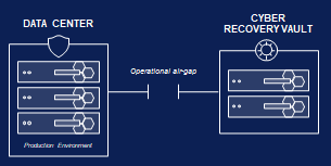 Figure 1. Air-gapped cyber recovery vault
AI visual intelligence
AI Visual Intelligence has been increasingly used across various industries for a multitude of purposes, including object recognition and classification, anomaly detection, predictive analytics, customer insights and experience enhancement, autonomous systems, healthcare diagnostics, environmental monitoring, and surveillance and security. By integrating AI Visual Intelligence into their operations, businesses can harness the power of visual data to improve decision-making, automate processes, enhance efficiencies, and unlock new opportunities for innovation and growth.
Video extends beyond security to impact business operations, enhancing efficiencies as the metadata collected from cameras serves business use cases beyond security functions. An example is the collection of this metadata, such as image metadata, timestamps, objects metadate, geo location, and more. The collection of this metadata necessitates a robust storage solution to preserve complete datasets readily available for models to achieve desired outcomes. This data is considered a mission-critical workload, demanding optimal uptime for storage solutions.
Adopting an N+X node-based storage architecture on-premises guarantees that data is consistently written and available, providing 99.9999% (6 nines) availability in an on-prem cloud environment. Dell Unstructured Data Solutions align perfectly with this workload, ensuring uninterrupted business operations compared to server-based storage solutions facing challenges during deployment or encountering issues with public cloud connectivity. The potential cost-prohibitive nature of public cloud storage for the data required in regular AI modeling may lead to a continued trend of cloud repatriation to on-premises.
Security practitioners evaluating the need for cameras must now strategically map out potential stakeholders within organizations to determine camera requirements aligned with their business outcomes. This strategic approach is anticipated to drive a higher demand for cameras and associated services.
Resources
Check out Dell PowerScale for more information about Dell PowerScale solutions.
Authors: Mordi Shushan, Brian Stonge

Introducing the Next Generation of PowerScale – the AI Ready Data Platform
Tue, 20 Feb 2024 19:07:47 -0000
|Read Time: 0 minutes
Generative AI systems thrive on vast amounts of unstructured data, which are essential for training algorithms to recognize patterns, make predictions, and generate new content. Unstructured data – such as text, images, and audio – does not follow a predefined model, making it more complex and varied than structured data.
Preprocessing unstructured data
Unstructured data does not have a predefined format or schema, including text, images, audio, video, or documents. Preprocessing unstructured data involves cleaning, normalizing, and transforming the data into a structured or semi-structured form that the AI can understand and that can be used for analysis or machine learning.
Preprocessing unstructured data for generative AI is a crucial step that involves preparing the raw data for use in training AI models. The goal is to enhance the quality and structure of the data to improve the performance of generative models.
There are different steps and techniques for preprocessing unstructured data, depending on the type and purpose of the data. Some common steps are:
- Data completion: This step involves filling in missing or incomplete data, either by using average or estimated values or by discarding or ignoring the data points with missing fields.
- Data noise reduction: This step involves removing or reducing irrelevant, redundant, or erroneous data, such as duplicates, spelling errors, hidden objects, or background noise.
- Data transformation: This step involves converting the data into a standard or consistent format, including scaling and normalizing numerical data, encoding categorical data, or extracting features from text, image, audio, or video data.
- Data reduction: This step involves reducing the dimensionality or size of the data, either by selecting a subset of relevant features or data points or by applying techniques such as principal component analysis, clustering, or sampling.
- Data validation: This step involves checking the quality and accuracy of the preprocessed data by using statistical methods, visualization tools, or domain knowledge.
These steps can help enhance the quality, reliability, and interpretability of the data, which can improve the performance and outcomes of the analysis or machine learning models.
PowerScale F210 and F710 platform
PowerScale’s continuous innovation extends into the AI era with the introduction of the next generation of PowerEdge-based nodes, including the PowerScale F210 and F710. The new PowerScale all-flash nodes leverage Dell PowerEdge R660, unlocking the next generation of performance. On the software front, the F210 and F710 take advantage of significant performance improvements in PowerScale OneFS 9.7. Combining the hardware and software innovations, the F210 and F710 tackle the most demanding workloads with ease.
The F210 and F710 offer greater density in a 1U platform, with the F710 supporting 10 NVMe SSDs per node and the F210 offering a 15.36 TB drive option. The Sapphire Rapids CPU provide 19% lower cycles-per-instruction. PCIe Gen 5 doubles throughput when compared to PCIe Gen 4. Additionally, the nodes take advantage of DDR5, offering greater speed and bandwidth.
From a software perspective, PowerScale OneFS 9.7 introduces a significant leap in performance. OneFS 9.7 updates the protocol stack, locking, and direct-write. To learn more about OneFS 9.7, check out this article on PowerScale OneFS 9.7.
The OneFS journal in the all-flash F210 and F710 nodes uses a 32 GB configuration of the Dell Software Defined Persistent Memory (SDPM) technology. Previous platforms used NVDIMM-n for persistent memory, which consumed a DIMM slot.
For more details about the F210 and F710, see our other blog post at Dell.com: https://www.dell.com/en-us/blog/next-gen-workloads-require-next-gen-storage/.
Performance
The introduction of the PowerScale F210 and F710 nodes capitalizes on significant leaps in hardware and software from the previous generations. OneFS 9.7 introduces tremendous performance-oriented updates, including the protocol stack, locking, and direct-write. The PowerEdge-based servers offer a substantial hardware leap from previous generations. The hardware and software advancements combine to offer enormous performance gains, particularly for streaming reads and writes.
PowerScale F210
The PowerScale F210 is a 1U chassis based on the PowerEdge R660. A minimum of three nodes is required to form a cluster, with a maximum of 252 nodes. The F210 is node pool compatible with the F200.

Table 1. F210 specifications
Attribute | PowerScale F210 Specification |
Chassis | 1U Dell PowerEdge R660 |
CPU | Single Socket – Intel Sapphire Rapids 4410Y (2G/12C) |
Memory | Dual Rank DDR5 RDIMMs 128 GB (8 x 16 GB) |
Journal | 1 x 32 GB SDPM |
Front-end networking | 2 x 100 GbE or 25 GbE |
Infrastructure networking | 2 x 100 GbE or 25 GbE |
NVMe SSD drives | 4 |
PowerScale F710
The PowerScale F710 is a 1U chassis based on the PowerEdge R660. A minimum of three nodes is required to form a cluster, with a maximum of 252 nodes.

Table 2. F710 specifications
Attribute | PowerScale F710 Specification |
Chassis | 1U Dell PowerEdge R660 |
CPU | Dual Socket – Intel Sapphire Rapids 6442Y (2.6G/24C) |
Memory | Dual Rank DDR5 RDIMMs 512 GB (16 x 32 GB) |
Journal | 1 x 32 GB SDPM |
Front-end networking | 2 x 100 GbE or 25 GbE |
Infrastructure networking | 2 x 100 GbE |
NVMe SSD drives | 10 |
For more details on the new PowerScale all-flash platforms, see the PowerScale All-Flash F210 and F710 white paper.
Author: Aqib Kazi

OneFS Access Control Lists Overview
Thu, 18 Jan 2024 22:29:13 -0000
|Read Time: 0 minutes
As we know, when users access OneFS cluster data via different protocols, the final permission enforcement happens on the OneFS file system. In OneFS, this is achieved by the Access Control Lists (ACLs) implementation, which provides granular permission control on directories and files. In this article, we will look at the basics of OneFS ACLs.
OneFS ACL
OneFS provides a single namespace for multiprotocol access and has its own internal ACL representation to perform access control. The internal ACL is presented as protocol-specific views of permissions so that NFS exports display POSIX mode bits for NFSv3 and ACL for NFSv4 and SMB.
When connecting to an PowerScale cluster with SSH, you can manage not only POSIX mode bits but also ACLs with standard UNIX tools such as chmod commands. In addition, you can edit ACL policies through the web administration interface to configure OneFS permissions management for networks that mix Windows and UNIX systems.
The OneFS ACL design is derived from Windows NTFS ACL. As such, many of its concept definitions and operations are similar to the Windows NTFS ACL, such as ACE permissions and inheritance.
OneFS synthetic ACL and real ACL
To deliver cross-protocol file access seamlessly, OneFS stores an internal representation of a file-system object’s permissions. The internal representation can contain information from the POSIX mode bits or the ACL.
OneFS has two types of ACLs to fulfill different scenarios:
- OneFS synthetic ACL: Under the default ACL policy, if no inheritable ACL entries exist on a parent directory – such as when a file or directory is created through a NFS or SSH session on OneFS within the parent directory – the directory will only contain POSIX mode bits permission. OneFS uses the internal representation to generate a OneFS synthetic ACL, which is an in-memory structure that approximates the POSIX mode bits of a file or directory for an SMB or NFSv4 client.
- OneFS real ACL: Under the default ACL policy, when a file or directory is created through SMB or when the synthetic ACL of a file or directory is modified through an NFSv4 or SMB client, the OneFS real ACL is initialized and stored on disk. The OneFS real ACL can also be initialized using the OneFS enhanced chmod command tool with the +a, -a, or =a option to modify the ACL.
OneFS access control entries
In contrast to the Windows DACL and NFSv4 ACL, the OneFS ACL access control entry (ACE) adds an additional identity type. OneFS ACEs contain the following information:
- Identity name: The name of a user or group
- ACE type: The type of the ACE (allow or deny)
- ACE permissions and inheritance flags: A list of permissions and inheritance flags separated with commas
OneFS ACE permissions
Similar to the Windows permission level, OneFS divides permissions into the following three types:
- Standard ACE permissions: These apply to any object in the file system
- Generic ACE permissions: These map to a bundle of specific permissions
- Constant ACE permissions: These are specific permissions for file-system objects
The standard ACE permissions that can appear for a file-system object are shown in the following table:
ACE permission | Applies to | Description |
std_delete | Directory or file | The right to delete the object |
std_read_dac | Directory or file | The right to read the security descriptor, not including the SACL |
std_write_dac | Directory or file | The right to modify the DACL in the object's security descriptor |
std_write_owner | Directory or file | The right to change the owner in the object's security descriptor |
std_synchronize | Directory or file | The right to use the object as a thread synchronization primitive |
std_required | Directory or file | Maps to std_delete, std_read_dac, std_write_dac, and std_write_owner |
The generic ACE permissions that can appear for a file system object are shown in the following table:
ACE permission | Applies to | Description |
generic_all | Directory or file | Read, write, and execute access. Maps to file_gen_all or dir_gen_all. |
generic_read | Directory or file | Read access. Maps to file_gen_read or dir_gen_read. |
generic_write | Directory or file | Write access. Maps to file_gen_write or dir_gen_write. |
generic_exec | Directory or file | Execute access. Maps to file_gen_execute or dir_gen_execute. |
dir_gen_all | Directory | Maps to dir_gen_read, dir_gen_write, dir_gen_execute, delete_child, and std_write_owner. |
dir_gen_read | Directory | Maps to list, dir_read_attr, dir_read_ext_attr, std_read_dac, and std_synchronize. |
dir_gen_write | Directory | Maps to add_file, add_subdir, dir_write_attr, dir_write_ext_attr, std_read_dac, and std_synchronize. |
dir_gen_execute | Directory | Maps to traverse, std_read_dac, and std_synchronize. |
file_gen_all | File | Maps to file_gen_read, file_gen_write, file_gen_execute, delete_child, and std_write_owner. |
file_gen_read | File | Maps to file_read, file_read_attr, file_read_ext_attr, std_read_dac, and std_synchronize. |
file_gen_write | File | Maps to file_write, file_write_attr, file_write_ext_attr, append, std_read_dac, and std_synchronize. |
file_gen_execute | File | Maps to execute, std_read_dac, and std_synchronize. |
The constant ACE permissions that can appear for a file-system object are shown in the following table:
ACE permission | Applies to | Description |
modify | File | Maps to file_write, append, file_write_ext_attr, file_write_attr, delete_child, std_delete, std_write_dac, and std_write_owner |
file_read | File | The right to read file data |
file_write | File | The right to write file data |
append | File | The right to append to a file |
execute | File | The right to execute a file |
file_read_attr | File | The right to read file attributes |
file_write_attr | File | The right to write file attributes |
file_read_ext_attr | File | The right to read extended file attributes |
file_write_ext_attr | File | The right to write extended file attributes |
delete_child | Directory or file | The right to delete children, including read-only files within a directory; this is currently not used for a file, but can still be set for Windows compatibility |
list | Directory | List entries |
add_file | Directory | The right to create a file in the directory |
add_subdir | Directory | The right to create a subdirectory |
traverse | Directory | The right to traverse the directory |
dir_read_attr | Directory | The right to read directory attributes |
dir_write_attr | Directory | The right to write directory attributes |
dir_read_ext_attr | Directory | The right to read extended directory attributes |
dir_write_ext_attr | Directory | The right to write extended directory attributes |
OneFS ACL inheritance
Inheritance allows permissions to be layered or overridden as needed in an object hierarchy and allows for simplified permissions management. The semantics of OneFS ACL inheritance are the same as Windows ACL inheritance and will feel familiar to someone versed in Windows NTFS ACL inheritance. The following table shows the ACE inheritance flags defined in OneFS:
ACE inheritance flag | Set on directory or file | Description |
object_inherit | Directory only | Indicates an ACE applies to the current directory and files within the directory |
container_inherit | Directory only | Indicates an ACE applies to the current directory and subdirectories within the directory |
inherit_only | Directory only | Indicates an ACE applies to subdirectories only, files only, or both within the directory. |
no_prop_inherit | Directory only | Indicates an ACE applies to the current directory or only the first-level contents of the directory, not the second-level or subsequent contents |
inherited_ace | File or directory | Indicates an ACE is inherited from the parent directory |
Author: Lieven Lin

CloudPools Operation Workflows
Fri, 12 Jan 2024 21:01:01 -0000
|Read Time: 0 minutes
The Dell PowerScale CloudPools feature of OneFS allows tiering cold or infrequently accessed data to move to lower-cost cloud storage. CloudPools extends the PowerScale namespace to the private cloud, or the public cloud. For CloudPools supported cloud providers, see the CloudPools Supported Cloud Providers blog.
This blog focuses on the following CloudPools operation workflows:
- Archive
- Recall
- Read
- Update
Archive
The archive operation is the CloudPools process of moving file data from the local PowerScale cluster to cloud storage. Files are archived either using the SmartPools Job or from the command line. The CloudPools archive process can be paused or resumed.
The following figure shows the workflow of the CloudPools archive.
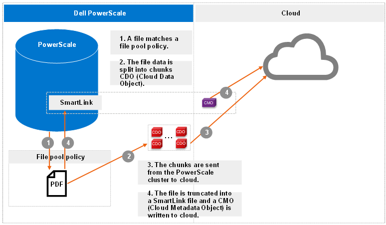
Figure 1. Archive workflow
More workflow details include:
- The file pool policy in Step 1 specifies a cloud target and cloud-specific parameters. Policy examples include:
- Encryption: CloudPools provides an option to encrypt data before the data is sent to the cloud storage. It uses the PowerScale key management module for data encryption and uses AES-256 as the encryption algorithm. The benefit of encryption is that only encrypted data is being sent over the network.
- Compression: CloudPools provides an option to compress data before the data is sent to the cloud storage. It implements block-level compression using the zlib compression library. CloudPools does not compress data that is already compressed.
- Local data cache: Caching is used to support local reading and writing of SmartLink files. To optimize performance, it reduces bandwidth costs by eliminating repeated fetching of file data for repeated reads and writes. The data cache is used for temporarily caching file data from the cloud storage on PowerScale disk storage for files that have been moved off cluster by CloudPools.
- Data retention: Data retention is a concept used to determine how long to keep cloud objects on the cloud storage.
- When chunks are sent from the PowerScale cluster to cloud in Step 3, a checksum is applied for each chunk to ensure data integrity.
Recall
The recall operation is the CloudPools process of reversing the archive process. It replaces the SmartLink file by restoring the original file data on the PowerScale cluster and removing the cloud objects in cloud. The recall process can only be performed using the command line. The CloudPools recall process can be paused or resumed.
The following figure shows the workflow of CloudPools recall.
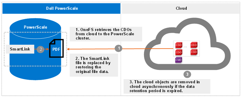
Figure 2. Recall workflow
Read
The read operation is the CloudPools process of client data access, known as inline access. When a client opens a file for read, the blocks are added to the cache in the associated SmartLink file by default. The cache can be disabled by setting the accessibility in the file pool policy for CloudPools. The accessibility setting is used to specify how data is cached in SmartLink files when a user or application accesses a SmartLink file on the PowerScale cluster. Values are cached (default) and no cache.
The following figure shows the workflow of CloudPools read by default.
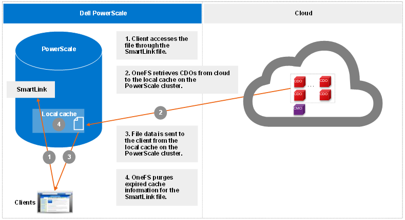
Figure 3. Read workflow
Starting from OneFS 9.1.0.0, cloud object cache is introduced to enhance CloudPools functions for communicating with cloud. In Step 1, OneFS looks for data in the object cache first and OneFS retrieves data from the object cache if the data is already in the object cache. Cloud object cache reduces the number of requests to cloud when reading a file.
Prior to OneFS 9.1.0.0, in Step 1, OneFS looks for data in the local data cache first. It moves to Step 3 if the data is already in the local data cache.
Note: Cloud object cache is per node. Each node maintains its own object cache on the cluster.
Update
The update operation is the CloudPools process that occurs when clients update data. When clients change to a SmartLink file, CloudPools first writes the changes in the data local cache and then periodically sends the updated file data to cloud. The space used by the cache is temporary and configurable.
The following figure shows the workflow of CloudPools update.
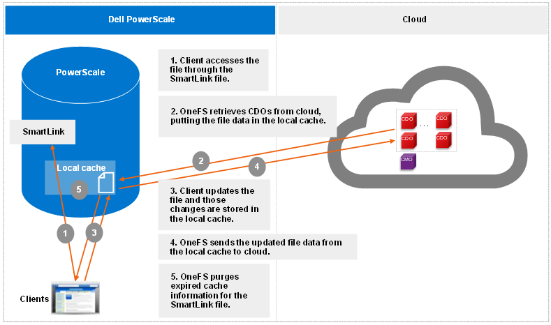
Figure 4. Update workflow
Thank you for taking the time to read this blog, and congratulations on gaining a clear understanding of how the OneFS CloudPools operation works!
Author: Jason He, Principal Engineering Technologist

CloudPools Reporting
Fri, 12 Jan 2024 20:33:21 -0000
|Read Time: 0 minutes
This blog focuses on CloudPools reporting, specifically:
- CloudPools network stats
- The isi_fsa_pools_usage feature
CloudPools network stats
Dell PowerScale CloudPools network stats collect every network transaction and provide network activity statistics from CloudPools connections to the cloud storage.
Displaying network activity statistics
The network activity statistics include bytes In, bytes Out, and the number of GET, PUT, and DELETE operations. CloudPools network stats are available in two categories:
- Per CloudPools account
- Per file pool policy
Note: CloudPools network stats do not provide file statistics, such as the file list being archived or recalled.
Run the following command to check the CloudPools network stats by CloudPools account:
isi_test_cpool_stats -Q --accounts <account_name>
For example, the following command shows the current CloudPools network stats by CloudPools account:
isi_test_cpool_stats -Q --accounts testaccount
Account Name   Bytes In    Bytes Out   Num Reads   Num Writes   Num Deletes
testaccount    4194896000  4194905034  4000        2001         8001
Similarly, you can run the following command to check the CloudPools network stats by file pool policy:
isi_test_cpool_stats -Q --policies <policy_name>
And here is an example of current CloudPools network stats by file pool policy:
isi_test_cpool_stats -Q --policies testpolicy
Policy Name    Bytes In       Bytes Out      Num Reads      Num Writes
testpolicy     4154896000     4154905034     4000           2001
Note: The command output does not include the number of deletes by file pool policy.
Run the following command to check the history for CloudPools network stats:
isi_test_cpool_stats -q –s <number of seconds in the past to start stat query>
Use the s parameter to define the number of seconds in the past. For example, set it as 86,400 to query CloudPools network stats over the last day, as in the following example:
isi_test_cpool_stats -q -s 86400
Account          bytes-in     bytes-out    gets   puts   deletes
testaccount    | 4194896000 | 4194905034 | 4000 | 2001 | 8001
You can also run the following command to flush stats from memory to database and get the real-time CloudPools network stats:
isi_test_cpool_stats -f
Displaying stats for CloudPools activities
The cloud statistics namespace with CloudPools is added in OneFS 9.4.0.0. This feature leverages existing OneFS daemons and systems to track statistics about CloudPools activities. The statistics include bytes In, bytes Out, and the number of Reads, Writes, and Deletions. CloudPools statistics are available in two categories:
- Per CloudPools account
- Per file pool policy
Note: The cloud statistics namespace with CloudPools does not provide file statistics, such as the file list being archived or recalled.
You can run these isi statistics cloud commands to view statistics about CloudPools activities:
isi statistics cloud --account <account_name>
isi statistics cloud --policy <policy_name>
The following command shows an example of current CloudPools statistics by CloudPools account:
isi statistics cloud --account s3
Account Policy In      Out     Reads   Writes  Deletions       Cloud      Node
s3             218.5KB 218.7KB 1       2       0               AWS        3
s3             0.0B    0.0B    0       0       0               AWS        1
s3             0.0B    0.0B    0       0       0               AWS        2
The following command shows an example of current CloudPools statistics by file pool policy:
isi statistics cloud --policy s3policy
Account Policy         In      Out     Reads   Writes  Deletions  Cloud       Node
s3      s3policy       218.5KB 218.7KB  1      2       0          AWS         3
s3      s3policy       0.0B    0.0B     0      0       0          AWS         1
s3      s3policy       0.0B    0.0B     0      0       0          AWS         2
The isi_fsa_pools_usage feature
Starting from OneFS 8.2.2, you can run the following command to list Logical Size and Physical Size of stubs in one directory. This feature leverages IndexUpdate and FSA (File System Analytics) jobs. To enable this feature, it requires:
- Scheduling the IndexUpdate job. It’s recommended to run it every four hours.
- Scheduling the FSA job. It’s recommended to run it every day, but not more often than the IndexUpdate job.
isi_fsa_pools_usage /ifs
Node Pool                  Dirs  Files  Streams  Logical Size   Physical Size
Cloud                      0     1       0       338.91k           24.00k
h500_30tb_3.2tb-ssd_128gb  42    300671  0       879.23G            1.20T
Now, you get how to use commands for CloudPools reporting. It’s simple and straightforward. Thanks for reading!
Author: Jason He, Principal Engineering Technologist

Protecting CloudPools SmartLink Files
Fri, 12 Jan 2024 17:20:14 -0000
|Read Time: 0 minutes
Dell PowerScale CloudPools SmartLink files are the sole means to access file data stored in the cloud, so ensure that you protect them from accidental deletion.
Note: SmartLink files cannot be backed up using a copy command, such as secure copy (scp).
This blog focuses on backing up SmartLink files using OneFS SyncIQ and NDMP (Network Data Management Protocol).
When the CloudPools version differs between the source cluster and the target PowerScale cluster, the CloudPools cross-version compatibility is handled.
NDMP and SyncIQ provide two types of copy or backup:
- Shallow copy (SC)/backup: Replicates or backs up SmartLink files to the target PowerScale cluster or tape as SmartLink files without file data.
- Deep copy (DC)/backup: Replicates or backs up SmartLink files to the target PowerScale cluster or tape as regular files or unarchived files. The backup or replication will be slower than for a shallow copy backup. Disk space will be consumed on the target cluster for replicating data.
The following table shows the CloudPools and OneFS mapping information. CloudPools 2.0 is released along with OneFS 8.2.0. CloudPools 1.0 is running in OneFS 8.0.x or 8.1.x.
Table 1. CloudPools and OneFS mapping information
OneFS version | CloudPools version |
OneFS 8.0.x/OneFS 8.1.x | CloudPools 1.0 |
OneFS 8.2.0 or higher | CloudPools 2.0 |
The following table shows the NDMP and SyncIQ supported use cases when different versions of CloudPools are running on the source and target clusters. As noted in the following table, if CloudPools 2.0 is running on the source PowerScale cluster and CloudPools 1.0 is running on the target PowerScale cluster, shallow copies are not allowed.
Table 2. NDMP and SyncIQ supported use cases with CloudPools
Source | Target | SC NDMP | DC NDMP | SC SyncIQ replication | DC SyncIQ replication |
CloudPools 1.0 | CloudPools 2.0 | Supported | Supported | Supported | Supported |
CloudPools 2.0 | CloudPools 1.0 | Not Supported | Supported | Not Supported | Supported |
SyncIQ
SyncIQ is CloudPools-aware but consider the guidance in snapshot efficiency, especially where snapshot retention periods on the target cluster will be long.
SyncIQ policies support two types of data replication for CloudPools:
- Shallow copy: This option is used to replicate files as SmartLink files without file data from the source PowerScale cluster to the target PowerScale cluster.
- Deep copy: This option is used to replicate files as regular files or unarchived files from the source PowerScale cluster to the target PowerScale cluster.
SyncIQ, SmartPools, and CloudPools licenses are required on both the source and target PowerScale cluster. It is highly recommended to set up a scheduled SyncIQ backup of the SmartLink files.
When SyncIQ replicates SmartLink files, it also replicates the local cache state and unsynchronized cache data from the source PowerScale cluster to the target PowerScale cluster. The following figure shows the SyncIQ replication when replicating directories including SmartLink files and unarchived normal files. Both unidirectional and bi-directional replication are supported.
Note: OneFS manages cloud access at the cluster level and does not support managing cloud access at the directory level. When failing over a SyncIQ directory containing SmartLink files to a target cluster, you need to remove cloud access on the source cluster and add cloud access on the target cluster. If there are multiple CloudPools storage accounts, removing/adding cloud access will impact all CloudPools storage accounts on the source/target cluster.
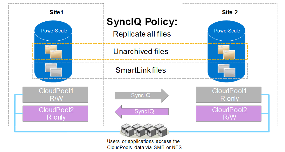
Figure 1. SyncIQ replication
Note: If encryption is enabled in a file pool policy for CloudPools, SyncIQ also replicates all the relevant encryption keys to the secondary PowerScale cluster along with the SmartLink files.
NDMP
NDMP is also CloudPools-aware and supports three backup and restore methods for CloudPools:
- DeepCopy: This option is used to back up files as regular files or unarchived files. Files can only be restored as regular files.
- ShallowCopy: This option is used to back up files as SmartLink files without file data. Files can only be restored as SmartLink files.
- ComboCopy: This option is used to back up files as SmartLink files with file data. Files can be restored as regular files or SmartLink files.
It is possible to update the file data and send the updated data to the cloud storage. Multiple version SmartLink files can be backed up to tape using NDMP, and multiple versions of CDOs (Cloud Data Objects) are protected in the cloud under the data retention setting. You can restore a specific version of a SmartLink file from tape to a PowerScale cluster and continue to access (read or update) the file as before.
Note: If encryption is enabled in the file pool policy for CloudPools, NDMP also backs up all the relevant encryption keys to tapes along with the SmartLink files.
Thank you for taking the time to read this blog, and congratulations on knowing the solutions for protecting SmartLink files using OneFS SyncIQ and NDMP.
Author: Jason He, Principal Engineering Technologist

How to Size Disk Capacity When Cluster Has Data Reduction Enabled
Mon, 08 Jan 2024 18:22:11 -0000
|Read Time: 0 minutes
When sizing a storage solution for OneFS, two major aspects need to be considered – capacity and performance. In this blog, we will talk about how to calculate the raw capacity in each node in the AWS cloud environment.
Consider a customer who wants to have 30TB of data capacity on APEX File Storage on AWS. The data reduction ratio is 1.6, and the cluster contains 6 nodes. How much capacity is needed for each node of the cluster?
1. The usable capacity is calculated by dividing the application data size by the data reduction ratio: 30TB/1.6 = 18.75TB
2. OneFS in the AWS environment uses +2n as the default protection level. The +2n protection level striping pattern of 6 nodes is 4+2. The raw capacity necessary can be calculated by dividing the usable capacity by the striping pattern for the number of nodes involved: 18.75TB/66% = 28.41TB
3. Single disk capacity is then calculated by dividing the total raw capacity by the number of nodes involved: 28.41TB/6 nodes = 4.735TB
4. When each node contains 10 disks, each disk’s raw capacity should be 474GB.
OK, let's take a look at the formula of this calculation:
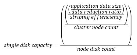
For reference, the striping patterns of 4, 5, and 6 nodes are listed as follows:
* 4 nodes: 2+2 (50%)
* 5 nodes: 3+2 (60%)
* 6 nodes: 4+2 (66%)
Now, knowing the logical data capacity, you can calculate the appropriate amount of capacity of each single EBS volume in the cluster.
Author: Yunlong Zhang

Running COSBench Performance Test on PowerScale
Tue, 09 Jan 2024 14:21:02 -0000
|Read Time: 0 minutes
Starting with OneFS version 9.0, PowerScale enables data access through the Amazon Simple Storage Service (Amazon S3) application programing interface (API) natively. PowerScale implements the S3 API as a first-class protocol along with other NAS protocols on top of its distributed OneFS file system.
COSBench is a popular benchmarking tool to measure the performance of Cloud Object Storage services and supports the S3 protocol. In the following blog, we will walk through how to set up COSBench to test the S3 performance of an PowerScale cluster.
Step 1:Choose v0.4.2.c4 version
I suggest choosing the v0.4.2 release candidate 4 instead of the latest v0.4.2 release, especially if you receive an error message like the following and your COSBench service cannot be started:
# cat driver-boot.log
Listening on port 0.0.0.0/0.0.0.0:18089 ...
!SESSION 2020-06-03 10:12:59.683 -----------------------------------------------
eclipse.buildId=unknown
java.version=1.7.0_261
java.vendor=Oracle Corporation
BootLoader constants: OS=linux, ARCH=x86_64, WS=gtk, NL=en_US
Command-line arguments:  -console 18089
!ENTRY org.eclipse.osgi 4 0 2020-06-03 10:13:00.367
!MESSAGE Bundle plugins/cosbench-castor not found.
!ENTRY org.eclipse.osgi 4 0 2020-06-03 10:13:00.368
!MESSAGE Bundle plugins/cosbench-log4j not found.
!ENTRY org.eclipse.osgi 4 0 2020-06-03 10:13:00.368
!MESSAGE Bundle plugins/cosbench-log@6:start not found.
!ENTRY org.eclipse.osgi 4 0 2020-06-03 10:13:00.369
!MESSAGE Bundle plugins/cosbench-config@6:start not found.
Step 2: Install Java
Both Java 1.7 and 1.8 work well with COSBench.
Step 3: Config ncat
Ncat is necessary for COSBench to work. Without it, you will receive the following error message:
[root]hopisdtmelabs14# bash ./start-driver.sh
Launching osgi framwork ...
Successfully launched osgi framework!
Booting cosbench driver ...
which: no nc in (/usr/local/bin:/usr/local/sbin:/usr/local/bin:/usr/sbin:/usr/bin:/root/bin:/usr/local/tme/bin:/usr/local/tme/tme_portal/perf_web/bin)
No appropriate tool found to detect cosbench driver status.
Use the following commands to install Ncat (example here is CentOS 7) and config it for COSBench:
yum -y install wget
wget [https://nmap.org/dist/ncat-7.80-1.x86_64.rpm](https://nmap.org/dist/ncat-7.80-1.x86_64.rpm)
yum localinstall ncat-7.80-1.x86_64.rpm
cd /usr/bin
ln -s ncat nc
Step 4: Unzip the COSBench files
After you download the 0.4.2.c4.zip, you can unzip it to a directory:
unzip 0.4.2.c4.zip
Grant all the bash script permission to be executed:
chmod +x /tmp/cosbench/0.4.2.c4/*.sh
Step 5: Start drivers and controller
On drivers and controller, find the cosbench-start.sh. Locate the java launching line, then add the following two options:
-Dcom.amazonaws.services.s3.disableGetObjectMD5Validation=true
-Dcom.amazonaws.services.s3.disablePutObjectMD5Validation=true
The COSBench tool has two roles: controller and driver. You can use the following command to start the driver:
bash ./cosbench/start-driver.sh
Before we start the controller, we need to change the configuration to let the controller knows how many drivers it has and their addresses. This is done by filling in information in the controller's main configuration file. The configuration file is under ./conf, and the name of the file is controller.conf. Following is an example of the controller.conf:
[controller]
drivers = 4
log_level = INFO
log_file = log/system.log
archive_dir = archive

[driver1]
name = driver1
url = [http://10.245.109.115:18088/driver](http://10.245.109.115:18088/driver)

[driver2]
name = driver2
url = [http://10.245.109.116:18088/driver](http://10.245.109.116:18088/driver)

[driver3]
name = driver3
url = [http://10.245.109.117:18088/driver](http://10.245.109.117:18088/driver)

[driver4]
name = driver4
url = [http://10.245.109.118:18088/driver](http://10.245.109.118:18088/driver)
Run the start-controller.sh to start the controller role:
bash ./start-controller.sh
Step 6: Prepare PowerScale
First, you need to prepare your PowerScale cluster for the S3 test. Make sure to record the secret key of the newly created user, s3. Run the following commands to prepare PowerScale for the S3 performance test:
isi services s3 enable
isi s3 settings global modify --https-only=false
isi auth users create s3 --enabled=true
isi s3 keys create s3
mkdir -p -m 777 /ifs/s3/bkt1
chmod 777 /ifs/s3
isi s3 buckets create --owner=s3 --name=bkt1  --path=/ifs/s3/bkt1
Compose the workload XML file, and use it to specify the details of the test you want to run. Here is an example:
<?xml version="1.0" encoding="UTF-8"?>
<workload name="S3-F600-Test1" description="Isilon F600 with original configuration">
        <storage type="s3" config="accesskey=1_s3_accid;secretkey=wEUqWNWkQGmgMos70NInqW26WpGf;endpoint=http://f600-2:9020/bkt1;path_style_access=true"/>
        <workflow>
               <workstage name="init-for-write-1k">
                       <work type="init" workers="1" config="cprefix=write-bucket-1k; containers=r(1,6)"/>
               </workstage>
               <workstage name="init-for-read-1k">
                       <work type="init" workers="1" config="cprefix=read-bucket-1k; containers=r(1,6)"/>
               </workstage>
               <workstage name="prepare-1k">
                       <work type="prepare" workers="1" config="cprefix=read-bucket-1k;containers=r(1,6);oprefix=1kb_;objects=r(1,1000);sizes=c(1)KB"/>
               </workstage>
               <workstage name="write-1kb">
                       <work name="main" type="normal" interval="5" division="container" chunked="false" rampup="0" rampdown="0" workers="6" totalOps="6000">
                               <operation type="write" config="cprefix=write-bucket-1k; containers=r(1,6); oprefix=1kb_; objects=r(1,1000); sizes=c(1)KB"/>
                       </work>
               </workstage>
               <workstage name="read-1kb">
                       <work name="main" type="normal" interval="5" division="container" chunked="false" rampup="0" rampdown="0" workers="6" totalOps="6000">
                               <operation type="read" config="cprefix=read-bucket-1k; containers=r(1,6); oprefix=1kb_; objects=r(1,1000)"/>
                       </work>
               </workstage>
        </workflow>
</workload>
Step 7: Run the test
You can directly submit the XML in the COSBench WebUI, or you can use the following command line in the controller console to start the test:
bash ./cli.sh submit ./conf/my-s3-test.xml
You will see the test successfully finished, as shown in the following figure.

Figure 1. Completion screen after testing
Have fun testing!
Author: Yunlong Zhang

Will More Disks Lead to Better Performance in APEX File Storage in AWS?
Mon, 08 Jan 2024 18:02:59 -0000
|Read Time: 0 minutes
Dell Technologies has developed a range of PowerScale platforms, including all flash models, hybrid models, and archive models, all of which exhibit exceptional design. The synergy between the disk system and the compute system is highly effective, showcasing a well-matched integration.
In the cloud environment, customers have the flexibility to control the number of CPU cores and memory sizes by selecting different instance types. APEX File Storage for AWS uses EBS volumes as its node disks. Customers can also select a different number of EBS volumes in each node, and for gp3 volumes, customers are able to customize the performance of each volume by specifying the throughput or IOPS capability.
With this level of flexibility, how shall we configure the disk system to make the most out of the entire OneFS system? Typically, in an on-prem appliance, the more disks a PowerScale node contains, the better performance the disk system can provide thanks to a greater number of devices contributing to the delivery of throughput or IOPS.
In a OneFS cloud environment, does it hold true that more EBS volumes indicates better performance? In short, it depends. When the aggregated EBS volume performance is smaller than the instance EBS bandwidth limit, test results show that more EBS volumes can improve performance. When aggregated EBS volume performance is larger than EBS bandwidth limit, adding more EBS volumes will not improve performance.
What is the best practice of setting the number of EBS volumes of each node?
1. Make the aggregated EBS volume bandwidth limit match the instance type EBS bandwidth limit.
For example, we want to use m5dn.16xlarge as the instance type of our OneFS cloud system. According to AWS, the EBS Bandwidth of m5dn.16xlarge is 13,600 Mbps, which is 1700 MB/sec. If we choose to use 10 EBS volumes in each node, then we should config each gp3 EBS volume to be capable of delivering 170 MB/sec throughput. This will make the aggregated EBS volume throughput equal to the m5dn.16xlarge EBS bandwidth limit.
Note that each gp3 EBS volume has 125MB/sec free throughput and 3,000 IOPS for free. As a cost-saving measure, we can config each node to have 12 EBS volumes to better leverage free EBS volume throughput.
For example, considering an m5dn.16xlarge instance type with 12 TB raw capacity per node, the disk cost of 10 volumes and 12 volumes are as follows:
- For 10 drives, each EBS volume should support 170 MB/sec throughput, and each node EBS storage cost is 1001.2 USD a month.
- For 12 drives, each EBS volume should support 142 MB/sec throughput, and each node EBS storage cost is 991.20 USD a month.
Using 12 EBS volumes can save $10 per node per month.
2. Do not set up more than 12 EBS volumes in each node.
Although APEX File Storage for AWS also supports 15, 18, and 20 gp3 volumes in each node, we do not recommend configuring more than 12 EBS volumes in each node for OneFS 9.7. This is best practice for keeping software journal space for each disk from being too small and is beneficial for write performance.
Author: Yunlong Zhang

Simplifying OneFS Deployment on AWS with Terraform
Wed, 20 Dec 2023 20:07:34 -0000
|Read Time: 0 minutes
In the first release of APEX File Storage for AWS in May 2023, users gained the capability to execute file workloads in the AWS cloud, thus harnessing the power of the PowerScale OneFS scale-out NAS storage solution. However, the initial implementation required the manual provisioning of all necessary AWS resources to provision the OneFS cluster—a less than optimal experience for embarking on the APEX File Storage journey in AWS.
With the subsequent release of APEX File Storage for AWS in December 2023, we are pleased to introduce a new, user-friendly open-source Terraform module. This module is designed to enhance and simplify the deployment process, alleviating the need for manual resource provisioning. In this blog post, we will delve into the details of leveraging this Terraform module, providing you with a comprehensive guide to expedite your APEX File Storage deployment on AWS.
Overview of Terraform onefs module
Terraform onefs module is an open-source module for the auto-deployment of AWS resources for a OneFS cluster. It is released and licensed under the MPL-2.0 license. You can find more details on the onefs module from the Terraform Registry. The onefs module provides the following features to help you deploy APEX File Storage for AWS OneFS clusters in AWS:
- Provision necessary AWS resources for a single OneFS cluster, including EC2 instances, EBS volumes, placement group, and network interfaces.
- Expand cluster size by provisioning additional AWS resources, including EC2 instances, EBS volumes, and network interfaces.
Getting Started
To use the Terraform onefs module, you need a machine that has Terraform installed and can connect to your AWS account. After you have fulfilled the prerequisites in documentation, you can start to deploy AWS resources for a OneFS cluster.
This blog provides instructions for deploying the required AWS infrastructure resources for APEX File Storage for AWS with Terraform.This includes: EC2 instances, spread strategy placement group, network interfaces, and EBS volumes.
1. Get the latest version of the onefs module from the Terraform Registry.
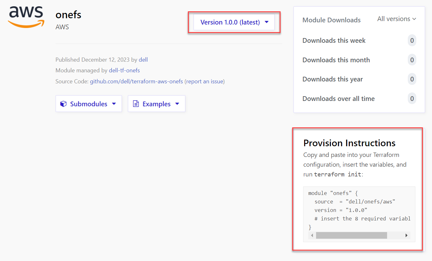
2. Prepare a main.tf file that uses the onefs module version collected in Step 1. The onefs module requires a set of input variables. The following is an example file named main.tf for creating a 4-nodes OneFS cluster.
module "onefs" {
source = "dell/onefs/aws"
version = "1.0.0"
region = "us-east-1"
availability_zone = "us-east-1a"
iam_instance_profile = "onefs-runtime-instance-profile"
name = "vonefs-cfv"
id = "vonefs-cfv"
nodes = 4
instance_type = "m5dn.12xlarge"
data_disk_type = "gp3"
data_disk_size = 1024
data_disks_per_node = 6
internal_subnet_id = "subnet-0c0106598b95ee7b6"
external_subnet_id = "subnet-0837801239d54e245"
contiguous_ips= true
first_external_node_hostnum = 5
internal_sg_id = "sg-0ee87249a52397219"
security_group_external_id = "sg-0635f298c9cb764da"
image_id = "ami-0f1a267119a34361c"
credentials_hashed = true
hashed_root_passphrase = "$5$9874f5d2c724b8ca$IFZZ5e9yfUVqNKVL82s.iFLIktr4WLavFhUVa8A"
hashed_admin_passphrase = "$5$9874f5d2c724b8ca$IFZZ5e9yfUVqNKVL82s.iFLIktr4WLavFhUVa8A"
dns_servers = ["169.254.169.253"]
timezone = "Greenwich Mean Time"
}
output "onefs-outputs" {
value = module.onefs
sensitive = true
}
3. Change your current working directory to the main.tf directory.
4. Initialize the module’s root directory by installing the required providers and modules for the deployment. In the following example, the onefs module is downloaded automatically from the Terraform Registry.
# terraform init
Initializing the backend...
Initializing modules...
Downloading registry.terraform.io/dell/onefs/aws 1.0.0 for onefs...
- onefs in .terraform\modules\onefs
- onefs.onefsbase in .terraform\modules\onefs\modules\base
- onefs.onefsbase.machineid in .terraform\modules\onefs\modules\machineid
Initializing provider plugins...
- Finding latest version of hashicorp/aws...
- Installing hashicorp/aws v5.30.0...
- Installed hashicorp/aws v5.30.0 (signed by HashiCorp)
5. Verify the configuration files in the onefs directory.
# terraform validate
6. Apply the configurations by running the following command.
# terraform apply
7. Enter “yes” after you have previewed and confirmed the changes.
Do you want to perform these actions?
Terraform will perform the actions described above.
Only 'yes' will be accepted to approve.
Enter a value: yes
8. Wait for the AWS resources to be provisioned. The output displays all the cluster information. If the deployment fails, re-run the terraform apply command to deploy.
Apply complete! Resources: 13 added, 0 changed, 0 destroyed.
Outputs:
onefs-outputs = <sensitive>
9. Get the cluster details information by running the following command.
# terraform output --json
The following example output is truncated.
additional_nodes = 3
cluster_id = "vonefs-cfv"
control_ip_address = "10.0.32.5"
external_ip_addresses = [
"10.0.32.5",
"10.0.32.6",
"10.0.32.7",
"10.0.32.8",
]
gateway_hostnum = 1
instance_id = [
"i-0eead1ee1dd67da6e",
"i-054efe96f6e605009",
"i-06e0b1ce06bad42a1",
"i-0e463c742974641d7",
]
internal_ip_addresses = [
"10.0.16.5",
"10.0.16.6",
"10.0.16.7",
"10.0.16.8",
]
internal_network_high_ip = "10.0.16.8"
internal_network_low_ip = "10.0.16.5"
mgmt_ip_addresses = []
node_configs = {
"0" = {
"external_interface_id" = "eni-09ddea1fd79f0d0ab"
"external_ips" = [
"10.0.32.5",
]
"internal_interface_id" = "eni-0caeee71581a8c429"
"internal_ips" = [
"10.0.16.5",
]
"mgmt_interface_id" = null
"mgmt_ips" = null /* tuple */
"serial_number" = "SV200-930073-0000"
}
"1" = {
"external_interface_id" = "eni-00869c96a27c20c93"
"external_ips" = [
"10.0.32.6",
]
"internal_interface_id" = "eni-0471bbba5a7f6596d"
"internal_ips" = [
"10.0.16.6",
]
"mgmt_interface_id" = null
"mgmt_ips" = null /* tuple */
"serial_number" = "SV200-930073-0001"
}
"2" = {
"external_interface_id" = "eni-0dac5052668bd3a4f"
"external_ips" = [
"10.0.32.7",
]
"internal_interface_id" = "eni-09d35ffa61b3dcd60"
"internal_ips" = [
"10.0.16.7",
]
"mgmt_interface_id" = null
"mgmt_ips" = null /* tuple */
"serial_number" = "SV200-930073-0002"
}
"3" = {
"external_interface_id" = "eni-028d211ef2d5b577c"
"external_ips" = [
"10.0.32.8",
]
"internal_interface_id" = "eni-02a99febea713f2d1"
"internal_ips" = [
"10.0.16.8",
]
"mgmt_interface_id" = null
"mgmt_ips" = null /* tuple */
"serial_number" = "SV200-930073-0003"
}
}
region = "us-east-1"
10. Write down the following output variables for setting up a cluster described in documentation.
- control_ip_address: The external IP address of the cluster’s first node
- external_ip_addresses: The external IP addresses of all provisioned cluster nodes
- internal_ip_addresses: The internal IP addresses of all provisioned cluster nodes
- internal_network_high_ip: The highest internal IP address assigned
- internal_network_low_ip: The lowest internal IP address assigned
- instance_id: The EC2 instance IDs of the cluster nodes
11. All AWS resources are now provisioned. After the cluster’s first node starts, it will form a single node cluster. You can use the cluster’s first node to add additional nodes to the cluster described in documentation. Below are the provisioned AWS EC2 instances with Terraform onefs module.
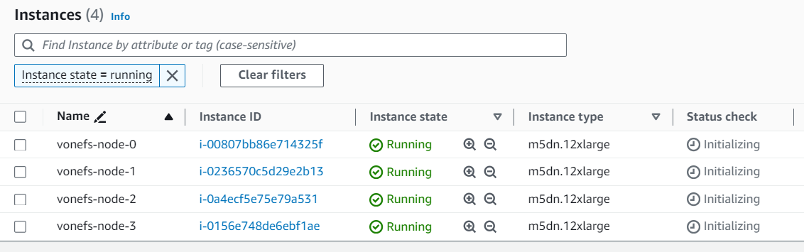
Available input variables
The Terraform onefs module provides a set of input variables for you to specify your own settings, including AWS resources and OneFS cluster, for example: AWS network resources, cluster name and password. See the table below for details used in the main.tf file.
Variable Name | Type | Description |
region | string | (Required) The AWS region of OneFS cluster nodes. |
availability_zone | string | (Required) The AWS availability zone of OneFS cluster nodes. |
iam_instance_profile | string | (Required) The AWS instance profile name of OneFS cluster nodes. For more details, see the AWS documentation Instance profiles. |
name | string | (Required) The OneFS cluster name. Cluster names must begin with a letter and can contain only numbers, letters, and hyphens. If the cluster is joined to an Active Directory domain, the cluster name must be 11 characters or fewer. |
id | string | (Required) The ID of the OneFS cluster. The onefs module uses the ID to add tags to the AWS resources. It is recommended to set the ID to your cluster name. |
nodes | number | (Required) The number of OneFS cluster nodes: it should be 4, 5, or 6. |
instance_type | string | (Required) The EC2 instance type of OneFS cluster nodes. All nodes in a cluster must have the same instance size. The supported instance sizes are:
Note: You must run PoC if you intend to use m5d.24xlarge or i3en.12xlarge EC2 instance types. For details, contact your Dell account team. |
data_disk_type | string | (Required) The EBS volume type for the cluster, gp3 or st1. |
data_disk_size | number | (Required) The single EBS volume size in GiB. Consider the Supported cluster configuration, it should be 1024 to 16384 for gp3, 4096 or 10240 for st1. |
data_disks_per_node | number | (Required) The number of EBS volumes per node. Consider the Supported cluster configuration, it should be 5, 6, 10, 12, 15, 18, or 20 for gp3, 5 or 6 for st1. |
internal_subnet_id | string | (Required) The AWS subnet ID for the cluster internal network interfaces. |
external_subnet_id | string | (Required) The AWS subnet ID for the cluster external network interfaces. |
contiguous_ips | bool | (Required) A boolean flag to indicate whether to allocate contiguous IPv4 addresses to the cluster nodes’ external network interfaces. It is recommended to set to true. |
first_external_node_hostnum | number | (Required if contiguous_ips=true) The host number of the first node’s external IP address in the given AWS subnet. Default is set to 5, The first four IP addresses in an AWS subnet are reserved by AWS, so the onefs module will allocate the fifth IP address to the cluster’s first node. If the IP is in use, the module will fail. Therefore, when setting contiguous_ips=true, ensure that you set a correct host number that has sufficient contiguous IPs for your cluster. Refer to Terraform cidrhost Function for more details about host number. |
internal_sg_id | string | (Required) The AWS security group ID for the cluster internal network interfaces. |
security_group_external_id | string | (Required) The AWS security group ID for the cluster external network interfaces. |
image_id | string | (Required) The OneFS AMI ID described in Find the OneFS AMI ID. |
credentials_hashed | bool | (Required) A boolean flag to indicate whether the credentials are hashed or in plain text. |
hashed_root_passphrase | string | (Required if credentials_hashed=true) The hashed root password for the OneFS cluster |
hashed_admin_passphrase | string | (Required if credentials_hashed=true) The hashed admin password for the OneFS cluster |
root_password | string | (Required if credentials_hashed=false) The root password for the OneFS cluster |
admin_password | string | (Required if credentials_hashed=false) The admin password for the OneFS cluster |
dns_servers | list(string) | (Optional) The cluster DNS server, default is set to ["169.254.169.253"], which is the AWS Route 53 Resolver. For details, see Amazon DNS server. |
dns_domains | list(string) | (Optional) The cluster DNS domain default is set to ["<region>.compute.internal"] |
timezone | string | (Optional) The cluster time zone, default is set to "Greenwich Mean Time". Several available options are: Greenwich Mean Time, Eastern Time Zone, Central Time Zone, Mountain Time Zone, Pacific Time Zone. You can change the time zone after the cluster is deployed by following the steps in the section OneFS documentation – Set the cluster date and time. |
resource_tags | map(string) | (Optional) The tags that will be attached to provisioned AWS resources. For example, resource_tags={“project”: “onefs-poc”, “tester”: “bob”}. |
Learn More
In this article, we have shown how to use Terraform onefs module. You can refer to the documentation below for more details about APEX File Storage for AWS:
- APEX File Storage for AWS
- Terraform onefs Module
- Technical white paper for AI use case: APEX File Storage for AWS with Amazon SageMaker
- Technical White Paper for M&E use case: APEX File Storage for AWS for Video Edit in AWS
- APEX File Storage for AWS Manual Deployment Guide
- APEX File Storage for AWS Deployment Guide with Terraform
- APEX File Storage for AWS Interactive Demo
Author: Lieven Lin

OneFS NDMP Backup Overview
Fri, 15 Dec 2023 15:00:00 -0000
|Read Time: 0 minutes
NDMP (Network Data Management Protocol) specifies a common architecture and data format for backups and restores of NAS (Network Attached Storage), allowing heterogeneous network file servers to directly communicate to tape devices for backup and restore operations. NDMP addresses the problems caused by the integrations of different backup software or DMA (Data Management Applications), file servers, and tape devices.
The NDMP architecture is a client/server model with the following characteristics:
- The NDMP host is a file server that is being protected with an NDMP backup solution.
- The NDMP server is a virtual state machine on the NDMP host that is controlled using NDMP.
- The backup software is considered as a client to the NDMP server.
OneFS supports the following two types of NDMP backups:
- NDMP two-way backup
- NDMP three-way backup
In both backup models, OneFS takes a snapshot of the backup directory to ensure consistency of data. The backup operates on the snapshot instead of the source directory, which allows users to continue read/write activities as normal. OneFS makes entries in the file history that are transferred from the PowerScale cluster to the backup server during the backup.
NDMP two-way backup
The NDMP two-way backup is also known as the local or direct NDMP backup, which is considered the most efficient model and usually provides the best performance. The backup moves the backup data directly from the PowerScale cluster to the tape devices without moving to the backup server over the network.
In this model, OneFS must detect the tape devices before you back up data to them. The PowerScale cluster provides the option for NDMP two-way backups as shown in the following figure. You can connect the PowerScale cluster to a Backup Accelerator node and connect tape devices to that node. The Backup Accelerator node is synonymous with a Fibre Attached Storage node without adding primary storage and offloads NDMP workloads from the primary storage nodes. You can directly connect tape devices to the Fibre Channel ports on the PowerScale cluster or Backup Accelerator node using Fibre Channel. Alternatively, you can connect Fibre Channel switches to the Fibre Channel ports that connect tape devices to the PowerScale cluster or Backup Accelerator node.
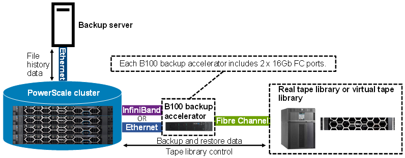 Figure 1. NDMP two-way backup with B100 backup accelerator connected to the PowerScale cluster
The following table shows details of the NDMP two-way backup supported by PowerScale:
NDMP two-way backup option | Generation 5 PowerScale nodes with an InfiniBand back end | Generation 6+ PowerScale nodes with an InfiniBand back end | Generation 6+ PowerScale nodes with an Ethernet back end |
B100 backup accelerator | Supported | Supported | Supported |
Note: The B100 backup accelerator requires OneFS 9.3.0.0 or later.
NDMP three-way backup
The NDMP three-way backup, also known as the remote NDMP backup, is shown in the following figure.
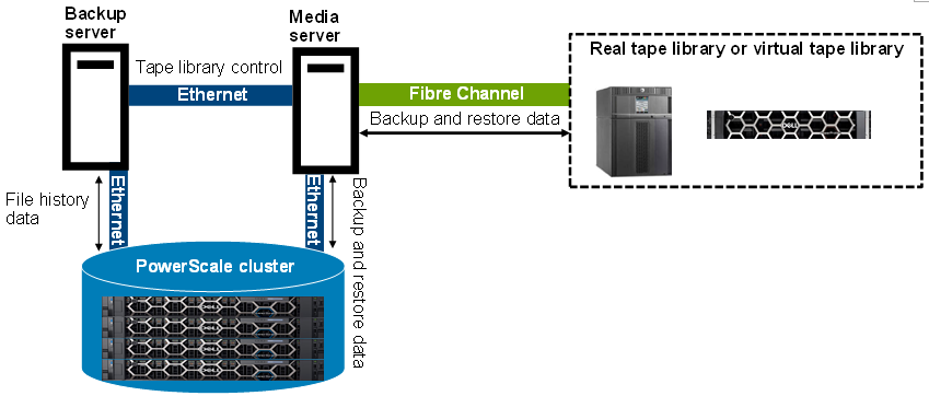 Figure 2. NDMP three-way backup
In this backup mode, the tape devices are connected to the backup media server. OneFS does not detect tape devices on the PowerScale cluster, and Fibre Channel ports are not required on the PowerScale cluster. The NDMP service runs on the NDMP server or the PowerScale cluster. The NDMP tape service runs on the backup media server. A DMA on the backup server instructs the PowerScale cluster to start backing up data from the PowerScale cluster to the backup media server over the network. The backup media server moves the backup data to tape devices. Both servers are connected to each other across the network boundary. Sometimes, the backup server and backup media server reside on the same physical machine.
For some specific DMA, DMA can write NDMP data to non-NDMP devices. For example, Dell NetWorker software writes NDMP data to non-NDMP devices, including tape, virtual tape, Advanced File Type Device (AFTD), and Dell PowerProtect DD series appliances. For more information on Data Protection with Dell NetWorker using NDMP, refer to this guide: Dell PowerScale: Data Protection with Dell NetWorker using NDMP.
Author: Jason He, Principal Engineering Technologist

Unveiling APEX File Storage for AWS Enhancements
Wed, 13 Dec 2023 15:36:10 -0000
|Read Time: 0 minutes
We are thrilled to announce the latest version of APEX File Storage for AWS! This release brings a multitude of enhancements to elevate your AWS file storage experience, including expanded AWS regions with the support for additional EC2 instance types, a Terraform module for streamlined deployment, larger raw capacity, and additional OneFS features support.
APEX File Storage delivers Dell’s leading enterprise-class high-performance scale-out file storage as a software-defined customer-managed offer in the public cloud. Based on PowerScale OneFS, APEX File Storage for AWS brings enterprise file capabilities and performance and delivers operational consistency across multicloud environments, simplifying hybrid cloud environments by facilitating seamless data mobility between on-premises and the cloud with native replication and making it the perfect option to run AI workloads. APEX File Storage can enhance customers’ development and innovation initiatives by combining proven data services such as multi-protocol access, security features, and a proven scale-out architecture with the flexibility of public cloud infrastructure and services. APEX File Storage enables organizations to run the software they trust directly in the public cloud without retraining their staff or refactoring their storage architecture.
What's New?
1. Additional EC2 instance types support
We've expanded compatibility by adding support for a wider range of EC2 instance types. This means you have more flexibility in choosing the instance type that best suits your performance and resource requirements. We now support the following EC2 instance types:
- EC2 m5dn instances: m5dn.8xlarge, m5dn.12xlarge, m5dn.16xlarge, m5dn.24xlarge
- EC2 m6idn instances: m6idn.8xlarge, m6idn.12xlarge, m6idn.16xlarge, m6idn.24xlarge
- EC2 m5d instances: m5d.24xlarge
- EC2 i3en instances: i3en.12xlarge
Please note that it is required to run PoC if you intend to use m5d.24xlarge or i3en.12xlarge EC2 instance types. Please contact your Dell account team for the details.
2. Extended AWS regions support
APEX File Storage is now available in more AWS regions than ever before. A total of 28 regions are available for you. We understand that our users operate globally, and this expansion ensures that you can leverage APEX File Storage wherever your AWS resources are located. The following table lists all available regions for different EC2 instance types:
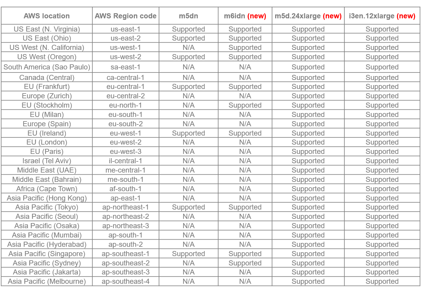
3. Terraform module: auto-deployment made effortless
Simplify your deployment process with our new Terraform module, which automates the AWS resource deployment process to ensure a smooth and error-free experience.
Once you fulfill the deployment prerequisites, you can deploy a cluster with a single Terraform command. For more details, refer to documentation: APEX File Storage for AWS Deployment Guide with Terraform. Stay tuned for a blog with additional details coming soon.
4. Larger raw capacity: more room for your data
Your data is growing, and so should your storage capacity. APEX File Storage for AWS can now support up to 1.6PiB raw capacity, enabling workloads that produce a vast amount of data such as AI and ensuring that you have ample space to store, manage, and scale your data effortlessly.
5. Additional OneFS features support
The OneFS features not supported in the first release of APEX File Storage for AWS are now supported, including:
- Enhanced Protocols: With HDFS protocol support, you can seamlessly integrate HDFS into your workflows, enhancing your data processing capabilities in AWS. Enjoy expanded connectivity with support for HTTP and FTP protocols, providing more flexibility in accessing and managing your files.
- Quality of Service – SmartQoS: Ensure a consistent and reliable user experience with SmartQoS, which enables you to prioritize workloads and applications based on performance requirements.
- Immutable Data Protection - SmartLock: Enhance data protection by leveraging SmartLock to create Write Once Read Many (WORM) files, providing an added layer of security against accidental or intentional data alteration.
- Large File Support: Address the needs of large-scale data processing with improved support for large files, facilitating efficient storage and retrieval. A single file size can be up to 16TiB now.
Learn More
For deployment instructions and detailed information on these exciting new features, refer to our documentation:
- APEX File Storage for AWS
- terraform-aws-onefs Terraform Module
- Technical white paper for AI use case: APEX File Storage for AWS with Amazon SageMaker
- Technical White Paper for M&E use case: APEX File Storage for AWS for Video Edit in AWS
- APEX File Storage for AWS Manual Deployment Guide
- APEX File Storage for AWS Deployment Guide with Terraform
- APEX File Storage for AWS Interactive Demo
Author: Lieven Lin

REST API in IIQ 5.0.0
Tue, 12 Dec 2023 15:00:00 -0000
|Read Time: 0 minutes
REST APIs have been introduced in IIQ 5.0.0, providing the equivalent of the CLI command in the previous IIQ version. CLI will not be available in IIQ 5.0.0. In order to understand how REST APIs work in IIQ, we will cover:
- REST API Authentication
- Creating a REST API Session
- Getting a REST API Session
- Managing PowerScale Clusters using REST API
- Exporting a Performance Report
- Deleting a REST API Session
Let’s get started!
REST API Authentication
IIQ 5.0.0 leverages JSON Web Tokens (JWT) along with x-csrf-token for session-based authentication. Following are some of the benefits of using JWTs:
- JWTs contains the user’s details
- JWTs incorporate digital signatures to ensure their integrity and protect against unauthorized modifications by potential attackers
- JWTs offer efficiency and rapid verification processes
Creating a REST API Session
A POST request to /insightiq/rest/security-iam/v1/auth/login/ will create a session with JWT cookie and x-csrf-token. A status code of 201 (Created) is returned upon successful user authentication. If the authentication process fails, the API responds with a status code of 401 (Unauthorized).
The following is an example of getting the JWT token with the POST method.
The POST request is:
curl -vk -X POST https://172.16.202.71:8000/insightiq/rest/security-iam/v1/auth/login -d '{"username": "administrator", "password": "a"}' -H 'accept: application/json' -H 'Content-Type: application/json'The POST response is:
Note: Unnecessary use of -X or --request, POST is already inferred.
*   Trying 172.16.202.71:8000...
* Connected to 172.16.202.71 (172.16.202.71) port 8000 (#0)
* ALPN: offers h2,http/1.1
* TLSv1.3 (OUT), TLS handshake, Client hello (1):
* TLSv1.3 (IN), TLS handshake, Server hello (2):
* TLSv1.3 (OUT), TLS change cipher, Change cipher spec (1):
* TLSv1.3 (OUT), TLS handshake, Client hello (1):
* TLSv1.3 (IN), TLS handshake, Server hello (2):
* TLSv1.3 (IN), TLS handshake, Encrypted Extensions (8):
* TLSv1.3 (IN), TLS handshake, Certificate (11):
* TLSv1.3 (IN), TLS handshake, CERT verify (15):
* TLSv1.3 (IN), TLS handshake, Finished (20):
* TLSv1.3 (OUT), TLS handshake, Finished (20):
* SSL connection using TLSv1.3 / TLS_AES_256_GCM_SHA384
* ALPN: server accepted h2
* Server certificate:
*  subject: O=Test; CN=cmo.ingress.dell
*  start date: Dec  4 05:59:14 2023 GMT
*  expire date: Dec  4 07:59:44 2023 GMT
*  issuer: C=US; ST=TX; L=Round Rock; O=DELL EMC; OU=Storage; CN=Platform Root CA; emailAddress=a@dell.com
*  SSL certificate verify result: unable to get local issuer certificate (20), continuing anyway.
* using HTTP/2
* h2h3 [:method: POST]
* h2h3 [:path: /insightiq/rest/security-iam/v1/auth/login]
* h2h3 [:scheme: https]
* h2h3 [:authority: 172.16.202.71:8000]
* h2h3 [user-agent: curl/8.0.1]
* h2h3 [accept: application/json]
* h2h3 [content-type: application/json]
* h2h3 [content-length: 46]
* Using Stream ID: 1 (easy handle 0x5618836b5eb0)
> POST /insightiq/rest/security-iam/v1/auth/login HTTP/2
> Host: 172.16.202.71:8000
> user-agent: curl/8.0.1
> accept: application/json
> content-type: application/json
> content-length: 46
>
* TLSv1.3 (IN), TLS handshake, Newsession Ticket (4):
* TLSv1.3 (IN), TLS handshake, Newsession Ticket (4):
* old SSL session ID is stale, removing
* We are completely uploaded and fine
< HTTP/2 201
< server: istio-envoy
< date: Mon, 04 Dec 2023 07:19:19 GMT
< content-type: application/json
< content-length: 54
< set-cookie: insightiq_auth=eyJ0eXAiOiJKV1QiLCJhbGciOiJQUzUxMiJ9.eyJjc3JmIjoiN3Z0eG5sMWRxbHIzaGtubGp3MjdwYXl3eW54bzQzdGs0Zmx4IiwiZXhwIjoxNzAxNzg5MTM5LCJpYXQiOjE3MDE3NDU5MzksImlzcyI6IkRlbGwgVGVjaG5vbG9naWVzIiwicm9sZSI6ImFkbWluIiwic2Vzc2lvbiI6InJ6ZnA3ZTRpMXdzd2xuYjBuNGo3YmQwNmF5dWs3emNkeXp1ZSIsInN1YiI6ImFkbWluaXN0cmF0b3IifQ.yKyfXbezscqn6UPa9fXxxjh71MCgeRAXPZhXkG-v92siwXAEP40ASb5bQUFHnAmWwwtlB4Jt8lX9kY8LmRkqi1V7B3v0LgxUp68heAc0HZAh6XO92ac9AfZ9dAuE9H3U4RNELm4vVx8mGrGmuzQymWUG5yRCNk03SpeW8esHnTPRVoGGsE4Cf6ta3BrUXBfic-D_TL01YgyY3Dy_T8Z1oqhkD508GPEYnEeNMU1QtZAwkmj6MJHtGmp69T0ljtQdIW2oi5xYdPs-ZHGSFRGG4j2o8xAEFV8A4igzP-5XOkE9NCcx2mkj67OdvVgNBxCcY-X7cnYyfLgagkanyQSgdA; Secure; HttpOnly; Path=/
< set-cookie: csrf_token=7vtxnl1dqlr3hknljw27paywynxo43tk4flx; Secure; HttpOnly; Path=/
< x-csrf-token: 7vtxnl1dqlr3hknljw27paywynxo43tk4flx
< x-envoy-upstream-service-time: 3179
< content-security-policy: default-src 'self' 'unsafe-inline' 'unsafe-eval' data:; style-src 'unsafe-inline' 'self';
< x-frame-options: sameorigin
< x-xss-protection: 1; mode=block
< x-content-type-options: nosniff
< referrer-policy: strict-origin-when-cross-origin
<
{"timeout_absolute":43200,"username":"administrator"}
* Connection #0 to host 172.16.202.71 left intact
The JWT cookie and x-csrf-token have been created and highlighted in the POST response section. The timeout for the session is 43,200 seconds (12 hours). You can save them for future uses:
export TOK="insightiq_auth=eyJ0eXAiOiJKV1QiLCJhbGciOiJQUzUxMiJ9.eyJjc3JmIjoiN3Z0eG5sMWRxbHIzaGtubGp3MjdwYXl3eW54bzQzdGs0Zmx4IiwiZXhwIjoxNzAxNzg5MTM5LCJpYXQiOjE3MDE3NDU5MzksImlzcyI6IkRlbGwgVGVjaG5vbG9naWVzIiwicm9sZSI6ImFkbWluIiwic2Vzc2lvbiI6InJ6ZnA3ZTRpMXdzd2xuYjBuNGo3YmQwNmF5dWs3emNkeXp1ZSIsInN1YiI6ImFkbWluaXN0cmF0b3IifQ.yKyfXbezscqn6UPa9fXxxjh71MCgeRAXPZhXkG-v92siwXAEP40ASb5bQUFHnAmWwwtlB4Jt8lX9kY8LmRkqi1V7B3v0LgxUp68heAc0HZAh6XO92ac9AfZ9dAuE9H3U4RNELm4vVx8mGrGmuzQymWUG5yRCNk03SpeW8esHnTPRVoGGsE4Cf6ta3BrUXBfic-D_TL01YgyY3Dy_T8Z1oqhkD508GPEYnEeNMU1QtZAwkmj6MJHtGmp69T0ljtQdIW2oi5xYdPs-ZHGSFRGG4j2o8xAEFV8A4igzP-5XOkE9NCcx2mkj67OdvVgNBxCcY-X7cnYyfLgagkanyQSgdA"
Getting a REST API Session
Use the GET method against /insightiq/rest/security-iam/v1/auth/session/ to get the session information. In the request header, include the cookie and the x-csrf-token field for authentication.
curl -k -v -X GET https://172.16.202.71:8000/insightiq/rest/security-iam/v1/auth/session --cookie $TOK -H 'accept: application/json' -H 'Content-Type: application/json' -H 'x-csrf-token: 7vtxnl1dqlr3hknljw27paywynxo43tk4flx'
The response is:
Note: Unnecessary use of -X or --request, GET is already inferred.
*   Trying 172.16.202.71:8000...
* Connected to 172.16.202.71 (172.16.202.71) port 8000 (#0)
* ALPN: offers h2,http/1.1
* TLSv1.3 (OUT), TLS handshake, Client hello (1):
* TLSv1.3 (IN), TLS handshake, Server hello (2):
* TLSv1.3 (OUT), TLS change cipher, Change cipher spec (1):
* TLSv1.3 (OUT), TLS handshake, Client hello (1):
* TLSv1.3 (IN), TLS handshake, Server hello (2):
* TLSv1.3 (IN), TLS handshake, Encrypted Extensions (8):
* TLSv1.3 (IN), TLS handshake, Certificate (11):
* TLSv1.3 (IN), TLS handshake, CERT verify (15):
* TLSv1.3 (IN), TLS handshake, Finished (20):
* TLSv1.3 (OUT), TLS handshake, Finished (20):
* SSL connection using TLSv1.3 / TLS_AES_256_GCM_SHA384
* ALPN: server accepted h2
* Server certificate:
*  subject: O=Test; CN=cmo.ingress.dell
*  start date: Dec  5 03:16:34 2023 GMT
*  expire date: Dec  5 05:17:04 2023 GMT
*  issuer: C=US; ST=TX; L=Round Rock; O=DELL EMC; OU=Storage; CN=Platform Root CA; emailAddress=a@dell.com
*  SSL certificate verify result: unable to get local issuer certificate (20), continuing anyway.
* using HTTP/2
* h2h3 [:method: GET]
* h2h3 [:path: /insightiq/rest/security-iam/v1/auth/session]
* h2h3 [:scheme: https]
* h2h3 [:authority: 172.16.202.71:8000]
* h2h3 [user-agent: curl/8.0.1]
* h2h3 [cookie: insightiq_auth=eyJ0eXAiOiJKV1QiLCJhbGciOiJQUzUxMiJ9.eyJjc3JmIjoiN3Z0eG5sMWRxbHIzaGtubGp3MjdwYXl3eW54bzQzdGs0Zmx4IiwiZXhwIjoxNzAxNzg5MTM5LCJpYXQiOjE3MDE3NDU5MzksImlzcyI6IkRlbGwgVGVjaG5vbG9naWVzIiwicm9sZSI6ImFkbWluIiwic2Vzc2lvbiI6InJ6ZnA3ZTRpMXdzd2xuYjBuNGo3YmQwNmF5dWs3emNkeXp1ZSIsInN1YiI6ImFkbWluaXN0cmF0b3IifQ.yKyfXbezscqn6UPa9fXxxjh71MCgeRAXPZhXkG-v92siwXAEP40ASb5bQUFHnAmWwwtlB4Jt8lX9kY8LmRkqi1V7B3v0LgxUp68heAc0HZAh6XO92ac9AfZ9dAuE9H3U4RNELm4vVx8mGrGmuzQymWUG5yRCNk03SpeW8esHnTPRVoGGsE4Cf6ta3BrUXBfic-D_TL01YgyY3Dy_T8Z1oqhkD508GPEYnEeNMU1QtZAwkmj6MJHtGmp69T0ljtQdIW2oi5xYdPs-ZHGSFRGG4j2o8xAEFV8A4igzP-5XOkE9NCcx2mkj67OdvVgNBxCcY-X7cnYyfLgagkanyQSgdA]
* h2h3 [accept: application/json]
* h2h3 [content-type: application/json]
* h2h3 [x-csrf-token: 7vtxnl1dqlr3hknljw27paywynxo43tk4flx]
* Using Stream ID: 1 (easy handle 0x561f902392c0)
> GET /insightiq/rest/security-iam/v1/auth/session HTTP/2
> Host: 172.16.202.71:8000
> user-agent: curl/8.0.1
> cookie: insightiq_auth=eyJ0eXAiOiJKV1QiLCJhbGciOiJQUzUxMiJ9.eyJjc3JmIjoiN3Z0eG5sMWRxbHIzaGtubGp3MjdwYXl3eW54bzQzdGs0Zmx4IiwiZXhwIjoxNzAxNzg5MTM5LCJpYXQiOjE3MDE3NDU5MzksImlzcyI6IkRlbGwgVGVjaG5vbG9naWVzIiwicm9sZSI6ImFkbWluIiwic2Vzc2lvbiI6InJ6ZnA3ZTRpMXdzd2xuYjBuNGo3YmQwNmF5dWs3emNkeXp1ZSIsInN1YiI6ImFkbWluaXN0cmF0b3IifQ.yKyfXbezscqn6UPa9fXxxjh71MCgeRAXPZhXkG-v92siwXAEP40ASb5bQUFHnAmWwwtlB4Jt8lX9kY8LmRkqi1V7B3v0LgxUp68heAc0HZAh6XO92ac9AfZ9dAuE9H3U4RNELm4vVx8mGrGmuzQymWUG5yRCNk03SpeW8esHnTPRVoGGsE4Cf6ta3BrUXBfic-D_TL01YgyY3Dy_T8Z1oqhkD508GPEYnEeNMU1QtZAwkmj6MJHtGmp69T0ljtQdIW2oi5xYdPs-ZHGSFRGG4j2o8xAEFV8A4igzP-5XOkE9NCcx2mkj67OdvVgNBxCcY-X7cnYyfLgagkanyQSgdA
> accept: application/json
> content-type: application/json
> x-csrf-token: 7vtxnl1dqlr3hknljw27paywynxo43tk4flx
>
* TLSv1.3 (IN), TLS handshake, Newsession Ticket (4):
* TLSv1.3 (IN), TLS handshake, Newsession Ticket (4):
* old SSL session ID is stale, removing
< HTTP/2 200
< server: istio-envoy
< date: Tue, 05 Dec 2023 03:19:41 GMT
< content-type: application/json
< content-length: 57
< x-envoy-upstream-service-time: 5
< content-security-policy: default-src 'self' 'unsafe-inline' 'unsafe-eval' data:; style-src 'unsafe-inline' 'self';
< x-frame-options: sameorigin
< x-xss-protection: 1; mode=block
< x-content-type-options: nosniff
< referrer-policy: strict-origin-when-cross-origin
<
{"username": "administrator", "timeout_absolute": 42758}
* Connection #0 to host 172.16.202.71 left intact
The response body will return the username of the session and its remaining timeout value in seconds.
Managing PowerScale Clusters using REST API
You can also use the IIQ REST API to manage your PowerScale cluster. Like what we’ve seen so far, all requests must include the parameter cookie and x-csrf-token for authentication. When adding clusters into IIQ, you will also need to provide the cluster IP with username and password. For details, refer to the following table:
Table 1. Using REST API to manage PowerScale Clusters
Exporting a Performance Report
To export a performance report from IIQ 5.0.0, you can use the GET method against /iiq/reporting/api/v1/timeseries/download_data with the following query parameters:
- cluster – PowerScale cluster id
- start_time – UNIX epoch timestamp of the beginning of the data range. Defaults to most recent saved report data and time.
- end_time – UNIX epoch timestamp of the end of the data range. Defaults to most recent saved report data and time.
- key – the performance key. To get a list of all the supported keys, use the GET method against http://<lP>:8000/iiq/reporting/api/v1/reports/data-element-types
Note: To get the performance key, use values from the response list for data-element-types in definition.timeseries_keys from data elements where report_group is equal to performance and definition.layout is equal to chart. See the following screenshot for an example. In this example, the performance key is ext_net.
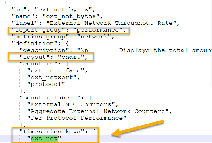 Figure 1. Getting the performance key where the key is ext_net
The following is an example of using the IIQ REST API to export the cluster performance of external network throughput to a CSV file:
curl -vk -X GET "https://10.246.159.113:8000/iiq/reporting/api/v1/timeseries/download_data?cluster=0007433384d03e80b4582103b56e1cac33a2&start_time=1694143511&end_time=1694366711&key=ext_net" -H 'x-csrf-token: vny27rem4l6ww29hvkhuaka0ix7x172wufbv' --cookie $TOK >>perf.csv
Deleting a REST API Session
To remove an IIQ REST API session, use the following API:
curl -k -v -X GET https://<EXTERNAL_IP>:8000/insightiq/rest/security-iam/v1/auth/logout --cookie <COOKIE> -H 'accept: application/json' -H 'Content-Type: application/json' -H 'x-csrf-token: <X-CSRF-TOKEN>'
Conclusion
The IIQ REST API is a powerful tool. Please refer to the Dell Technologies InsightIQ 5.0.0 User Guide for more information. For any questions, feel free to reach out to me at Vincent.shen@dell.com.
Author: Vincent Shen

Alert in IIQ 5.0.0 – Part I
Wed, 13 Dec 2023 17:40:06 -0000
|Read Time: 0 minutes
Alert is a new feature introduced with the release of IIQ 5.0.0. It provides the capability and flexibility to configure alerts based on the KPI threshold.
This blog will walk you through the following aspects of this feature:
- Introduction to Alert
- How to configure alerts using Alert
Let’s get started:
Introduction
IIQ 5.0.0 can send email alerts based on your defined KPI and threshold. The supported KPIs are listed in the following table:
KPI Name | Description | Scope |
Protocol Latency SMB | Average latency within last 10 minutes required for the various operations for the SMB protocol | Across all nodes and clients per cluster. |
Protocol Latency NFS | Average latency within last 10 minutes required for the various operations for the NFS protocol. | Across all nodes and clients per cluster. |
Active Clients NFS | The current number of active clients using NFS. The client is active when it is transmitting or receiving data. | Across all nodes per cluster. |
Active Clients SMB 1 | The current number of active clients using SMB 1. The client is active when it is transmitting or receiving data. | Across all nodes per cluster. |
Active Clients SMB 2 | The current number of active clients using SMB 2. The client is active when it is transmitting or receiving data. | Across all nodes per cluster. |
Connected Clients NFS | The current number of connected clients using NFS. The client is connected when it has an open TCP connection to the cluster. It can transmit or receive data or it can be in an idle state. | Across all nodes per cluster. |
Connected Clients SMB | The current number of connected clients using SMB. The client is connected when it has an open TCP connection to the cluster. It can transmit or receive data or it can be in an idle state. | Across all nodes per cluster. |
Pending Disk Operation Count | The average pending disk operation count within the last 10 minutes. It is the number of I/O operations that are pending at the file system level and waiting to be issued to an individual drive. | Across all disks per cluster. |
CPU Usage | The average usage of CPU cores including the physical cores and hyperthreaded core within last 10 minutes. | Across all nodes per cluster. |
Cluster Capacity | The current used capacity for the cluster. | N/A |
Nodepool Capacity | The current used capacity for the node pool in a cluster. | N/A |
Drive Capacity | The current used capacity for a drive in a cluster. | N/A |
Node Capacity | The current used capacity for a node in a cluster. | N/A |
Network Throughput Equivalency | Checks whether the network throughput for each node within the last 10 minutes is within the specified threshold percentage of the average network throughput of all nodes in the node pool for the same time. | Across all nodes per node pool. |
Each KPI requires a threshold and a severity level, together forming an alert rule. You can customize the alert rules to align with specific business use cases.
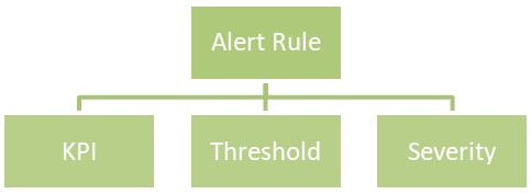
Here is an example of an alert rule:
If CPU usage (KPI) is greater than or equal to 96% (threshold), a critical alert (severity) will be triggered.
The supported severities are:
- Emergency
- Critical
- Warning
- Information
You can combine multiple alert rules into a single alert policy for easy management purposes.
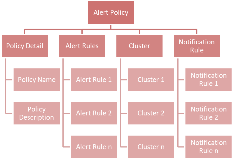
If you take a look at the chart above, you will find a new concept called Notification Rule. This is used to define the recipients' Email address and from what severity they will receive an Email:
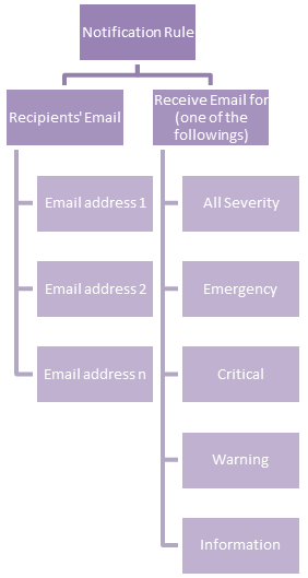
An example of a notification rule is like this: for user A (user_a@lled.com) and user B (user_b@lled.com), they both will receive Email alerts from all severity.
If you combine the above two examples and put them into the view of alert policy, you will get:
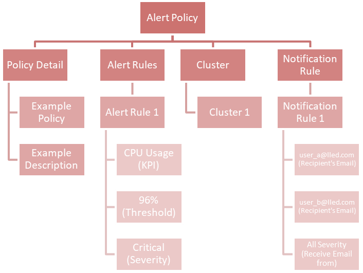
At this point, you should understand the big picture of the alert feature in IIQ 5.0.0. In my next post, I will walk you through the details of how to configure it.

Alert in IIQ 5.0.0 – Part II
Mon, 11 Dec 2023 16:10:19 -0000
|Read Time: 0 minutes
My previous post introduced one of the key features in IIQ 5.0.0 – Alert and explained how it works. In this blog, we will go into the details of how to configure it.
How to configure an alert in IIQ 5.0.0
Configure SMTP server in IIQ
Follow the steps below to add the SMTP server in IIQ:
- Access Configure SMTP under Settings from the left side menu.
- Enter the SMTP Server IP or FQDN. Username and Password are optional.
- Click the Save button.
You can send a test email to verify the settings.
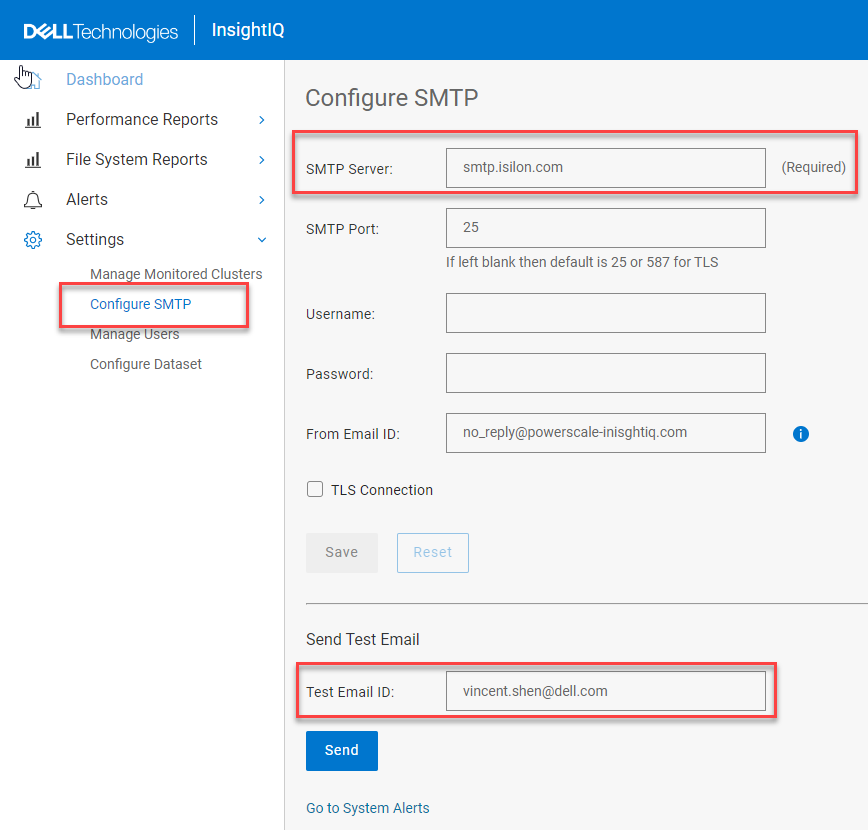
- SMTP configuration
Note: If you keep the SMTP Port number blank, the default will be 25 or 587 for TLS.
Manage Alerts
Create Alert Rules
To create alert rules, follow these steps:
- Navigate to Manage Alerts under Alerts from the left side menu.
- Click the Alert Rules.
- Click the Create Alert Rule button and a pop-up window will appear as shown below:
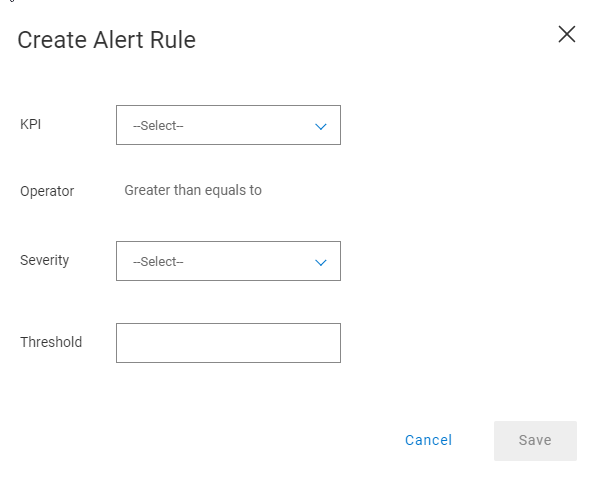
- Create Alert Rule
- Specify the KPI, Severity, and Threshold for it. Click the Save button.
- (Optional) You can create multiple Alert Rules.
Create a Notification Rule
A notification rule specifies the recipient(s) of SMTP alerts and its associated alert severity. To create a notification rule, follow these steps:
- Navigate to Manage Alerts located below Alerts from the left side menu.
- Click the Notification Rules.
- Click the button Create Notification Rule and it will pop up a window as shown below.
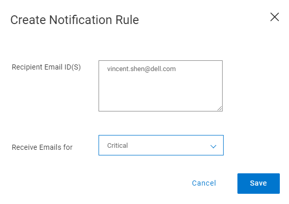
- Create Notification Rule
- Input the Recipient Email ID(s) and choose the severity from the dropdown list of Receive Emails for.
- Click the Save button.
Create an alert policy
To create an alert policy, follow these steps:
- Navigate to Manage Alerts located under Alerts from the left side menu.
- Click the Alert Policies.
- Click the Create Policy button.
- Input the Name and Description in the Policy Details window and click the Next button.
- In the Alert Rules subpage, you can choose either Existing Alert Rules or Create Alert Rule by clicking the corresponding button. After you create the alert rules, click the Next Button.
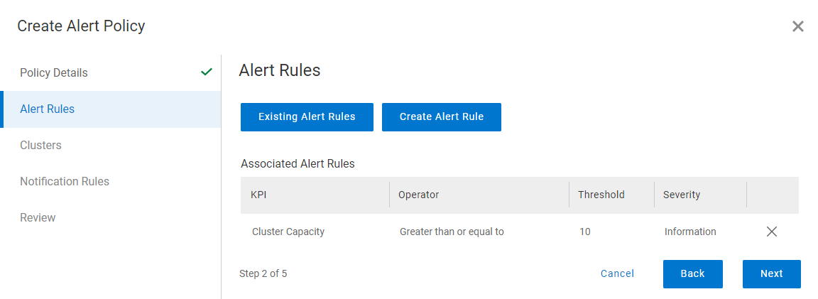
- Add Alert Rules
- On the Cluster subpage, choose the cluster to which you want to apply the alert settings, and click the Next button.
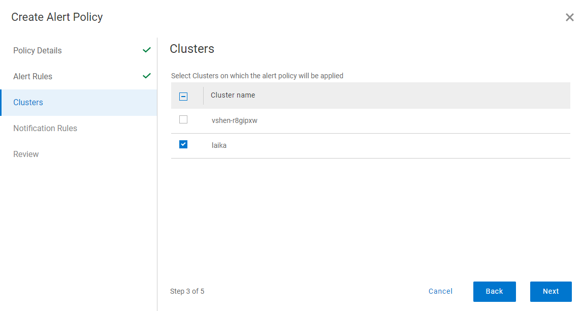
- Choose clusters
- On the Notification Rules subpage, you can choose either Existing Notification Rules or Create Notification Rule by clicking the corresponding button. After you choose the rule, click the Next button.
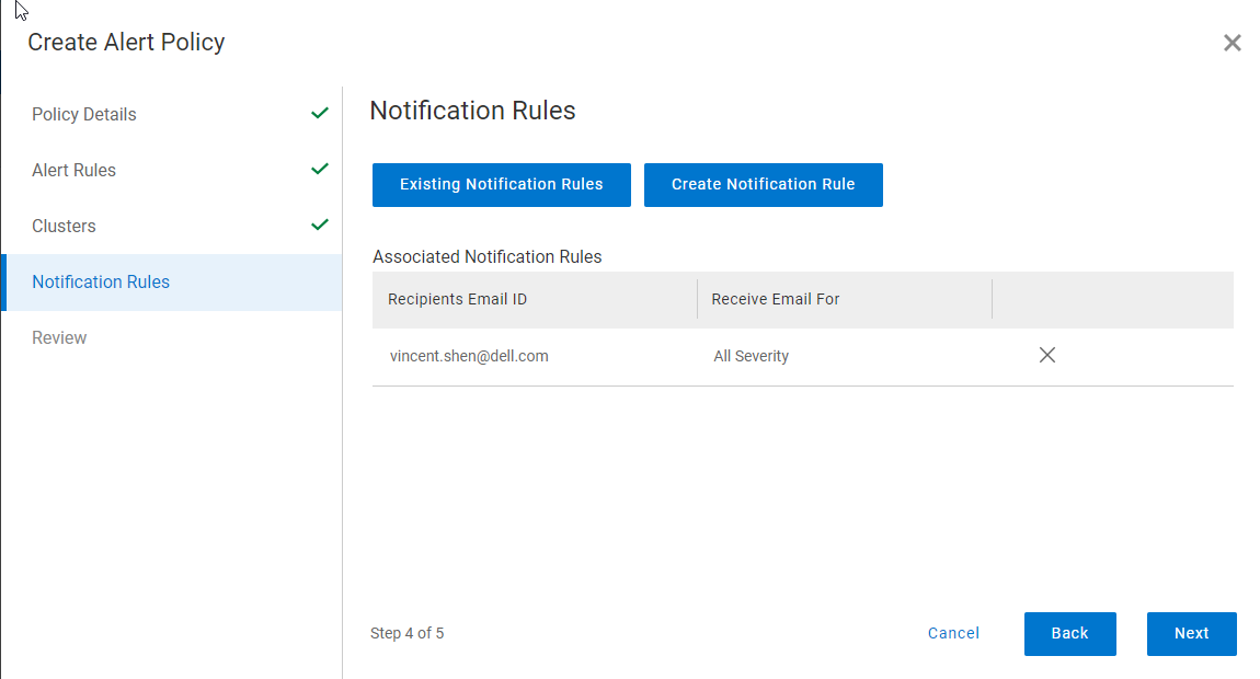
- Specify Notification Rules
- Click the Save button in the final Review subpage.
- The following screenshot is a sample alert email:

- Sample email alert
View Alerts
All the alerts can be accessed in Alerts > View Alerts from the left side menu.
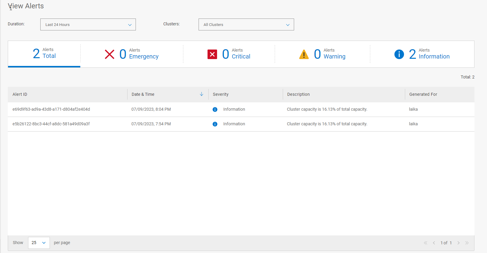
- View Alert
On this page you can:
- Filter alerts by selecting the Duration.
- Show alerts by choosing specific Clusters.
- Categorize alerts by different severity levels.
- Sort alerts by the Date & Time.
Hope you enjoy the reading. If you have any questions for suggestion on this feature, please feel free to reach out to me. (Vincent.shen@dell.com)

Mastering Monitoring and Reporting with InsightIQ 5.0.0
Mon, 11 Dec 2023 16:32:33 -0000
|Read Time: 0 minutes
Overview
In the complex landscape of data management, having robust tools to monitor and analyze your data is paramount. InsightIQ 5.0.0 is your gateway to exploring the depths of historical data sourced from PowerScale OneFS. By leveraging its capabilities, you can monitor cluster activities, analyze performance, and gain insights to ensure optimal functionality.
Monitoring Clusters with Dynamic Dashboard
The InsightIQ Dashboard stands as a central hub for monitoring all your clusters, offering a comprehensive overview of their statuses and vital statistics. The dashboard facilitates quick interpretation of data and the action-based navigation links allow you to easily check on the observed statuses.
Here's a breakdown of the essential sections within this powerful monitoring interface:
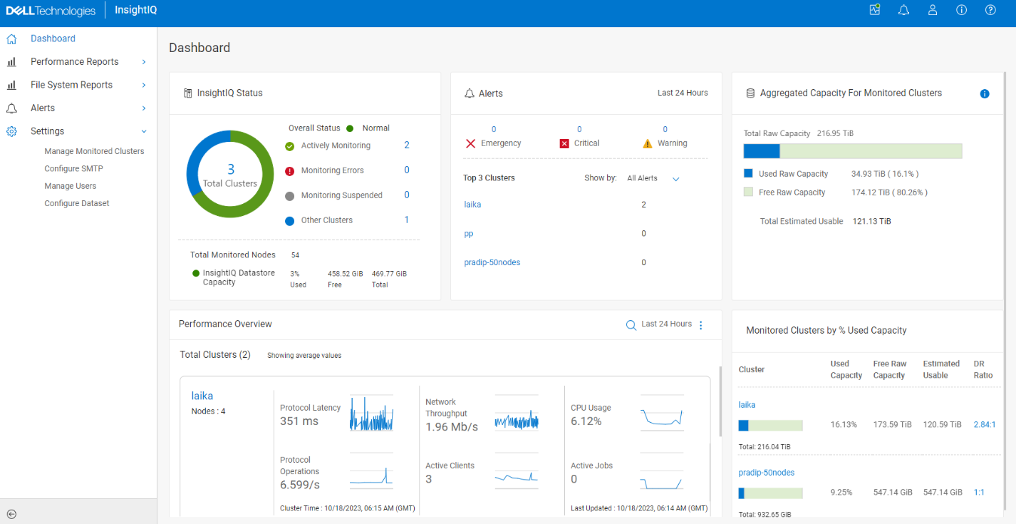
Figure 1 IIQ Dashboard
InsightIQ Status
This section provides an overview of connected clusters, highlighting monitoring errors and any suspended monitoring activities. The InsightIQ Status icons offer a quick assessment of the monitored clusters: green signifies active monitoring, red indicates monitoring errors, grey denotes suspended monitoring or incomplete credentials. There is a fourth status icon. Blue indicates the number of PowerScale clusters whose status is outside of green, red, or grey status values. This is typically due to an internal error.
Additionally, the InsightIQ Datastore Usage icons provide insights into datastore health, with green indicating health, yellow signaling near-full capacity, and red alerting that the datastore has reached its maximum limit.
Alerts
The Alerts section within InsightIQ is a pivotal area displaying crucial data accumulated over the past 24 hours, categorized by severity—emergency, critical, warning, and information. This section shows the top three clusters with the highest number of alerts, granting immediate visibility into potential issues impacting PowerScale clusters. The dashboard offers a swift way to access the 'Alerts' section, where you have the capability to create alerts, defining Key Performance Indicators (KPIs) and thresholds, easily viewable on the dashboard for prompt action. This comprehensive alert system ensures timely responses to potential issues.
Aggregated Capacity for monitored clusters
Get insights into the used and free raw capacity across monitored clusters, as well as the estimated total usable capacity.
Performance Overview
This section presents average values for critical performance metrics like protocol latency, network throughput, CPU usage, protocol operations, active clients, and active jobs, displaying changes in statistics over the past 24 hours. It also offers a convenient link to navigate to the 'View Performance Report', facilitating in-depth analysis across various metrics.
Monitored Clusters by % Used Capacity
This detailed breakdown showcases used capacity, free raw capacity, estimated usable capacity, and data reduction ratio for each monitored cluster. While it doesn't offer historical data, it provides real-time insights into the present cluster status. It offers quick navigation links to access both Capacity Reports and the Data Reduction Report for easy reference.
Performance and File System Reports
The heart of InsightIQ lies in its ability to provide detailed performance reports and file system reports. These reports can be standardized or tailored to your specific needs, enabling you to track storage cluster performance efficiently. You also have the flexibility to generate Performance Reports as PDF files on a predefined schedule, enabling easy distribution via email attachments.
InsightIQ reports are configured using modules, breakouts, and filter rules, providing a granular view of cluster components at specific data points. By employing modules and applying breakouts or filter rules, users can focus on distinct cluster components or specific attributes across the entire report. This flexibility allows the creation of tailored reports for various monitoring purposes.
Harnessing detailed metrics and insights empowers decision-making for crafting insightful performance reports. For instance, if network traffic surpasses anticipated levels across all monitored clusters, InsightIQ enables the creation of customized reports displaying detailed network throughput data. Analyzing direction-specific throughput assists in pinpointing any specific contribution to the overall traffic, aiding in precise troubleshooting and optimization strategies.
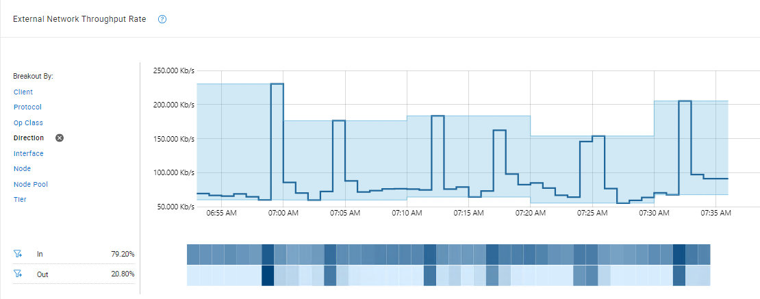
Figure 2 Sample Cluster Performance Report
Partitioned Performance
The Partition Performance report presents data from configurable datasets, offering insights into the top workloads consuming the most resources within a specific time range. Key data modules include: Dataset Summary, Workload Latency, Workload IOPS, Workload CPU Time, Workload Throughput, and Workload L2/L3 Cache Hits.
For more detailed information, users can focus on modules by average, top workload by max value, or pinned workload by average.
Note: access to the Partition Performance Report, the InsightIQ user on the PowerScale cluster needs ISI_PRIV_PERFORMANCE with read permission. If unable to view the report, contact the InsightIQ admin or refer to the Dell Technologies InsightIQ 5.0.0 Administration Guide for permission configuration.
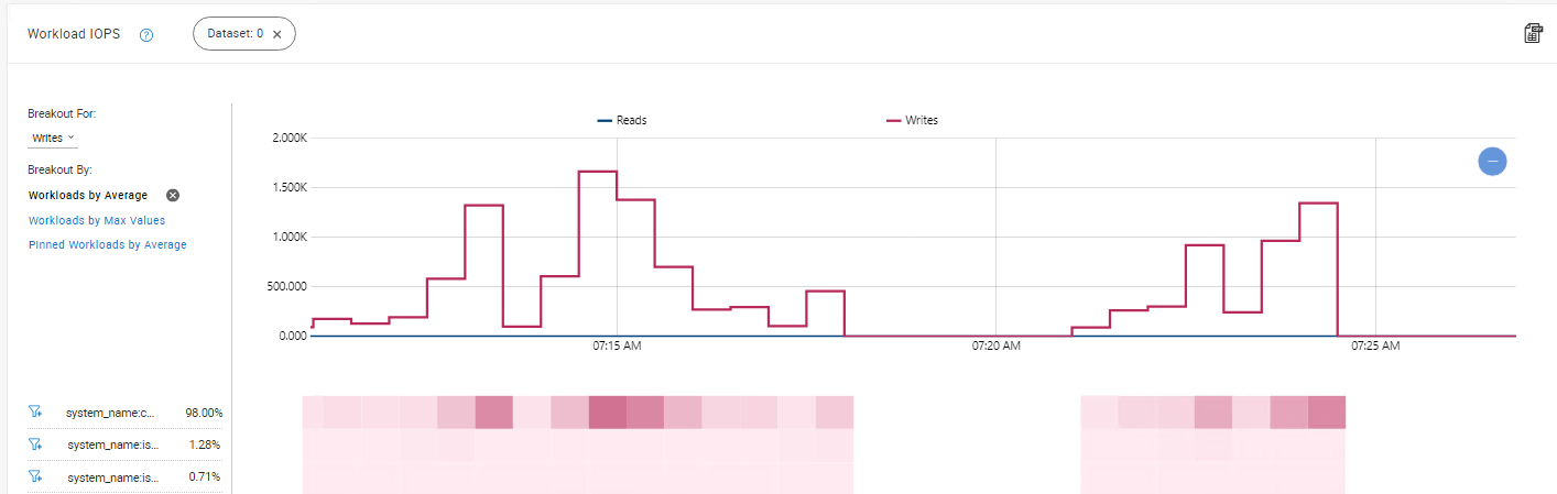
Figure 3 Sample Partitioned Performance Report
File System Analytic Report
File System Analytics (FSA) reports offer a comprehensive overview of the files stored within a cluster, providing essential insights into their types, locations, and usage.
InsightIQ supports two key FSA report categories:
- Data Usage reports focus on individual file data, revealing details like unchanged file durations.
- Data Property reports offer insights into the entire cluster file system, showcasing data such as file changes over specific periods and facilitating comparisons between different timeframes.
These reports help in understanding relative changes in file counts based on physical size, offering nuanced perspectives for effective file system management. For instance, by comparing Data Property reports of different clusters, you can observe patterns in file utilization—identifying clusters with regular file changes versus those housing less frequently modified files. Detecting inactive files through Data Usage reports facilitates efficient storage archiving strategies, optimizing cluster space.
These reports also play a pivotal role in verifying the expected behavior of cluster file systems. For example, dedicated archival clusters can be monitored using Data Property reports to observe file count changes. An unexpectedly high count might prompt storage admin to consider relocating files to development clusters, ensuring efficient resource utilization.
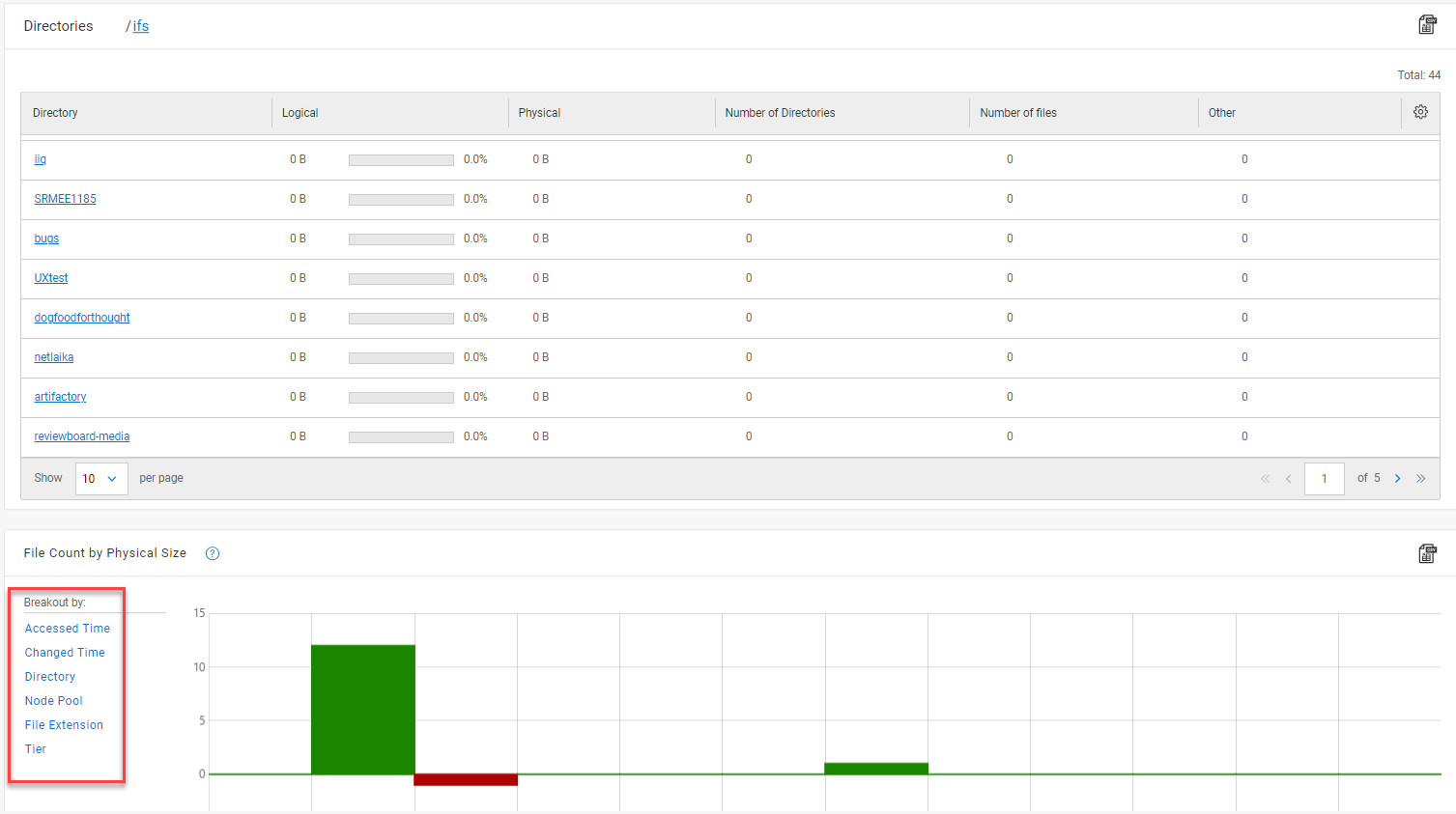
Figure 4 Data Properties Report
These FSA reports within InsightIQ not only provide visibility into cluster file systems but also serve as strategic tools for efficient storage management and troubleshooting unexpected discrepancies.
Conclusion: Empowering Data Management
InsightIQ isn't just a monitoring tool. It's a comprehensive suite offering a multitude of functionalities. It's about transforming data into actionable insights, enabling users to make informed decisions and stay ahead in the dynamic world of data management. The robust features, customizable reports, and analytics capabilities make it an invaluable asset for ensuring the optimal performance and health of PowerScale OneFS clusters.

Understanding InsightIQ 5.0.0 Deployment Options: Simple vs. Scale
Mon, 11 Dec 2023 16:32:33 -0000
|Read Time: 0 minutes
Overview
InsightIQ 5.0.0 introduces two distinct deployment options catering to varying scalability needs: InsightIQ Simple and InsightIQ Scale. Let's delve into the overview of both offerings to guide your deployment decision-making process.
InsightIQ Simple
Designed for the straightforward deployment and moderate scalability, IIQ Simple accommodates up to 252 nodes or 10 clusters. Here's a snapshot of its key requirements:
- Target Use Case: Simple deployment scenarios with moderate scaling requirements.
- Deployment Method: VMware-based deployment using the OVA template.
- OS Requirements: ESXi 7.0.3 and 8.0.2.
- Hardware Requirements: VMware hardware version 15 or higher, requires a CPU of 12 vCPU, 32GB memory, and 1.5TB disk space.
InsightIQ Scale
For organizations demanding extreme scalability, IIQ Scale steps in, supporting up to 504 nodes or 20 clusters, with potential expansion post IIQ 5.0. The details include:
- Target Use Case: Extreme scalability requirements.
- Deployment Method: RHEL-based deployment utilizing a specialized deployment script.
- OS Requirements: RHEL 8.6 x64.
- Hardware Requirements: Three virtual machines or physical servers, each with a configuration of 12 vCPU, 32GB memory, and specific storage options based on the chosen datastore location.
Here is the summary table:
InsightIQ Simple | InsightIQ Scale | |
Target Use Case | Simple deployment and moderate scalability – up to 252 nodes or 10 clusters | Extreme scalability – up to 504 nodes or 20 clusters (more in post-5.0) |
Deployment Method | On VMware, using OVA template | On Red Hat Enterprise Linux (RHEL) system, using an installation script |
OS Requirements | ESXi 7.0.3 and 8.0.2 | RHEL 8.6 x64 |
Hardware Requirements | VMware hardware version 15 and higher –
| Compute: 3 virtual machines or physical servers, with each VM or server having:
Storage:
|
Networking Requirements | 2 static IPs on the same network subnet, with PowerScale cluster connectivity | 4 static IPs on the same network subnet, with PowerScale cluster connectivity |
Leveraging the NFS export
In InsightIQ deployments, leveraging an NFS export for the datastore, whether from a PowerScale cluster or a Linux NFS server, can significantly enhance scalability. However, to ensure a seamless setup, specific prerequisites must be addressed:
Access and Permissions:
- Guarantee accessibility of the NFS server and export from all servers/VMs where InsightIQ is deployed. This accessibility is crucial for uninterrupted data flow.
- Set read/write permissions (chmod 777 <export_path>) to ensure unrestricted access for all users utilizing the NFS export.
Security Measures:
- Root User Mapping: Avoid mapping the root user (no_root_squash) to maintain secure access control.
- Mount Access: Enable mount access to subdirectories for streamlined data retrieval and utilization.
Resource Allocation:
- Allocate a substantial 1.5TB for the NFS export, ensuring ample space for data storage and future scalability.
- Allocate 200GB free space on the root partition ("/") of all servers/VMs hosting InsightIQ.
By ensuring compliance with these guidelines, organizations can unlock the full potential of InsightIQ while maintaining a robust and reliable infrastructure.
IIQ 5.0.0 Support Matrix
A concise summary detailing supported OneFS versions, host OS, recommended client display configurations, and browser compatibility for both IIQ Simple and IIQ Scale deployments.
InsightIQ uses TLS 1.3 exclusively. A web browser without TLS 1.3 enabled or supported cannot access InsightIQ 5.0.0.
InsightIQ Simple | InsightIQ Scale | |
PowerScale OneFS | From OneFS 9.2.0.0 to 9.5.x, OneFS 9.7.x | |
Host OS | ESXi 7.0.3 and 8.0.2 | RHEL 8.6 x64 |
Recommended Client display configuration |
| |
Supported Browser | Chrome (recommended) Mozilla Firefox Microsoft Edge | |
Summary
Unlocking the full potential of InsightIQ 5.0.0 is a journey that begins with a clear understanding of deployment options and their prerequisites. Embracing your organization's scalability needs and infrastructure nuances ensures a seamless

CloudPools Supported Cloud Providers
Thu, 07 Dec 2023 20:43:11 -0000
|Read Time: 0 minutes
The Dell PowerScale CloudPools feature of OneFS allows tiering, enabling you to move cold or infrequently accessed data to lower-cost cloud storage. CloudPools extends the PowerScale namespace to the private cloud and the public cloud.
This blog focuses on CloudPools supported cloud providers.
CloudPools supported cloud providers
Each cloud provider offers a range of storage classes that you can choose from based on data access and cost requirements. CloudPools does not support some specific storage classes that may cause CloudPools operations failure due to unacceptable object read/write latency.
Table 1. Supported and unsupported cloud providers and storage classes for CloudPools
Cloud providers | Supported storage classes | Unsupported storage classes |
All | N/A | |
S3 Standard |
| |
Hot access tier |
| |
| Archive storage | |
Standard |
|
To address cost requirements, users can move objects from higher cost storage class to lower cost storage class on the cloud. The tiers are as follows:
- Supported/Tier1 storage classes: CloudPools supports the storage classes.
- Tier2 storage classes: Amazon S3 supports using S3 Lifecycle policy to move CloudPools objects from the Tier1 storage class to the Tier2 storage class. This movement will not break CloudPools operations.
- Tier3 storage classes: Amazon S3 supports using S3 Lifecycle policy to move CloudPools objects from the Tier1 storage class to the Tier3 storage class. This movement will break CloudPools operations. CloudPools objects must first be moved to Tier2 storage class or Tier1 storage class to be accessed.
Table 2. Storage classes per tier per cloud provider in CloudPools
Cloud providers | Supported/Tier1 storage classes | Tier2 storage classes | Tier3 storage classes |
S3 Standard |
|
| |
Hot access tier |
|
| |
| Archive storage |
| |
Standard |
|
|
[1] Assumes no opt-in to Deep Archive Access Tier.
[2] Assumes real-time access is enabled.
[3] S3 directory buckets only allow objects stored in the S3 Express One Zone storage class and do not support S3 Lifecycle policies.
Resources
- Dell PowerScale: CloudPools and ECS
- Dell PowerScale: CloudPools and Amazon Web Services
- Dell PowerScale: CloudPools and Microsoft Azure
- Dell PowerScale: CloudPools and Google Cloud
- Dell PowerScale: CloudPools and Alibaba Cloud
Author: Jason He, Principal Engineering Technologist

Backing Up and Restoring PowerScale Cluster Configurations in OneFS 9.7
Wed, 13 Dec 2023 14:00:00 -0000
|Read Time: 0 minutes
Backing up and restoring OneFS cluster configurations is not new, as it was introduced in OneFS 9.2. However, only a limited set of components can be backed up or restored. This is a popular feature and we have received a lot of feedback that we should add more supported components. Now, with the release of OneFS 9.7, this feature gets a big enhancement. The following is a complete list of the components we support in 9.7. (The new ones are marked in blue.)
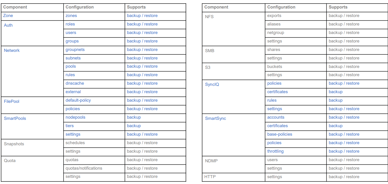
Some other enhancements include:
- Lock configuration during backup
- Support custom rules for restoring subnet IP addresses
Next, I’ll walk you through an example and explain the details of these enhancements.
Let’s take a look at the backup first.
Like what we have in the previous version, backup and restore are only available through PAPI and CLI (there is no WebUI at this stage). But I can guarantee you that the overall process is very simple and straightforward. If you are familiar with how to do it in the previous version, it’s almost the same.
You can use the following CLI command to back up a cluster configuration:
isi cluster config exports create [--components …]
Here is an example where I want to export the network configuration:
# isi cluster config exports create –components=Network
The following components’ configuration are going to be exported:
[‘Network’]
Notice:
    The exported configuration will be saved in plain text. It is recommended to encrypt it according to your specific requirements.
Do you want to continue? (yes/[no]): yes
This may take a few seconds, please wait a moment
Created export task ‘vshen-0eis0wn-20231128032252’
You can see that once the backup is triggered, a task is automatically created, and you can use the following command to view the details of the task:
isi cluster config exports view <export-id>
Here is what I have in my environment:
# isi cluster config exports view –id vshen-0eis0wn-20231128032252
     ID: vshen-0eis0wn-20231128032252
 Status: Successful
   Done: [‘network’]
 Failed: []
Pending: []
Message:
   Path: /ifs/data/Isilon_Support/config_mgr/backup/vshen-0eis0wn-20231128032252
During backup, to make a consistent configuration, a temporary lock is enabled to prevent new PAPI calls like POST, PUT, and DELETE. (The GET method will not be impacted.) In most cases, the backup job is completed quickly and it releases the lock when it finishes running.
You can use the following command to view the backup lock:
# isi cluster config lock view
Configuration lock enabled: Yes
You can also use the CLI command to manually enable or disable the lock:
# isi cluster config lock modify –action=enable
WARNING: User won’t be able to make any configuration changes after enabling configuration lock.
Are you sure you want to enable configuration lock? (yes/[no]): yes
After the backup task completes, the backup files will be generated under: /ifs/data/Isilon_Support/config_mgr/backup. Although the backup files are in plain text format, the sensitive information doesn’t appear here.
cat ./network_vshen-0eis0wn-20231128032252.json
{
  "description": {
    "component": "network",
    "release": "9.7.0.0",
    "action": "backup",
    "job_id": "vshen-0eis0wn-20231128032252",
    "result": "successful",
    "errors": []
  },
  "network": {
    "dnscache": {
      "cache_entry_limit": 65536,
       "cluster_timeout": 5,
       "dns_timeout": 5,
       "eager_refresh": 0,
       "testping_delta": 30,
       "ttl_max_noerror": 3600,
       "ttl_max_nxdomain": 3600,
…
When doing an import, you can use a command similar to the following:
# isi cluster config imports create --export-id=vshen-0eis0wn-20231128032252
Source Cluster Information:
          Cluster name: vshen-0eis0wn
       Cluster version: 9.7.0.0
            Node count: 1
  Restoring components: ['network']
Notice:
    Please review above information and make sure the target cluster has the same hardware configuration as the source cluster, otherwise the restore may fail due to hardware incompatibility. Please DO NOT use or change the cluster while configurations are being restored. Concurrent modifications are not guaranteed to be retained and some data services may be affected.
Do you want to continue? (yes/[no]): yes
This may take a few seconds, please wait a moment
Created import task 'vshen-0eis0wn-20231128064821'
When you deal with network component restore, to avoid connectivity breaks you can restore the configuration without destroying any existing subnets or pools’ IP addresses.
To do this, use the parameter “--network-subnets-ip”:
# isi cluster config imports create --export-id=vshen-0eis0wn-20231128032252 --network-subnets-ip="groupnet0.subnet0:10.242.114.0/24"
Source Cluster Information:
          Cluster name: vshen-0eis0wn
       Cluster version: 9.7.0.0
            Node count: 1
  Restoring components: ['network']
Notice:
    Please review above information and make sure the target cluster has the same hardware configuration as the source cluster, otherwise the restore may fail due to hardware incompatibility. Please DO NOT use or change the cluster while configurations are being restored. Concurrent modifications are not guaranteed to be retained and some data services may be affected.
Do you want to continue? (yes/[no]): yes
This may take a few seconds, please wait a moment
Created import task 'vshen-0eis0wn-20231128070157'
That’s how it works! As I said, it’s very simple and straightforward. If you see any errors, you can check the log: /var/log/config_mgr.log.
Author: Vincent Shen

PowerScale OneFS 9.7
Wed, 13 Dec 2023 13:55:00 -0000
|Read Time: 0 minutes
Dell PowerScale is already powering up the holiday season with the launch of the innovative OneFS 9.7 release, which shipped today (13th December 2023). This new 9.7 release is an all-rounder, introducing PowerScale innovations in Cloud, Performance, Security, and ease of use.
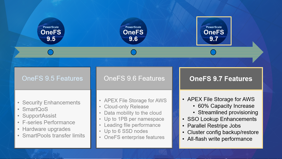
After the debut of APEX File Storage for AWS earlier this year, OneFS 9.7 extends and simplifies the PowerScale in the public cloud offering, delivering more features on more instance types across more regions.
In addition to providing the same OneFS software platform on-prem and in the cloud, and customer-managed for full control, APEX File Storage for AWS in OneFS 9.7 sees a 60% capacity increase, providing linear capacity and performance scaling up to six SSD nodes and 1.6 PiB per namespace/cluster, and up to 10GB/s reads and 4GB/s writes per cluster. This can make it a solid fit for traditional file shares and home directories, vertical workloads like M&E, healthcare, life sciences, finserv, and next-gen AI, ML and analytics applications.
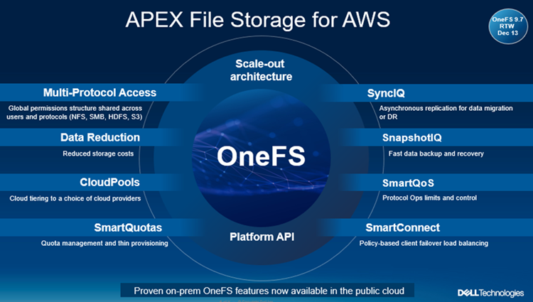
Enhancements to APEX File Storage for AWS
PowerScale’s scale-out architecture can be deployed on customer managed AWS EBS and ECS infrastructure, providing the scale and performance needed to run a variety of unstructured workflows in the public cloud. Plus, OneFS 9.7 provides an ‘easy button’ for streamlined AWS infrastructure provisioning and deployment.
Once in the cloud, you can further leverage existing PowerScale investments by accessing and orchestrating your data through the platform's multi-protocol access and APIs.
This includes the common OneFS control plane (CLI, WebUI, and platform API), and the same enterprise features: Multi-protocol, SnapshotIQ, SmartQuotas, Identity management, and so on.
With OneFS 9.7, APEX File Storage for AWS also sees the addition of support for HDFS and FTP protocols, in addition to NFS, SMB, and S3. Granular performance prioritization and throttling is also enabled with SmartQoS, allowing admins to configure limits on the maximum number of protocol operations that NFS, S3, SMB, or mixed protocol workloads can consume on an APEX File Storage for AWS cluster.
Security
With data integrity and protection being top of mind in this era of unprecedented cyber threats, OneFS 9.7 brings a bevy of new features and functionality to keep your unstructured data and workloads more secure than ever. These new OneFS 9.7 security enhancements help address US Federal and DoD mandates, such as FIPS 140-2 and DISA STIGs – in addition to general enterprise data security requirements. Included in the new OneFS 9.7 release is a simple cluster configuration backup and restore utility, address space layout randomization, and single sign-on (SSO) lookup enhancements.
Data mobility
On the data replication front, SmartSync sees the introduction of GCP as an object storage target in OneFS 9.7, in addition to ECS, AWS and Azure. The SmartSync data mover allows flexible data movement and copying, incremental resyncs, push and pull data transfer, and one-time file to object copy.
Performance improvements
Building on the streaming read performance delivered in a prior release, OneFS 9.7 also unlocks dramatic write performance enhancements, particularly for the all-flash NVMe platforms - plus infrastructure support for future node hardware platform generations. A sizable boost in throughput to a single client helps deliver performance for the most demanding GenAI workloads, particularly for the model training and inferencing phases. Additionally, the scale-out cluster architecture enables performance to scale linearly as GPUs are increased, allowing PowerScale to easily support AI workflows from small to large.
Cluster support for InsightIQ 5.0
The new InsightIQ 5.0 software expands PowerScale monitoring capabilities, including a new user interface, automated email alerts, and added security. InsightIQ 5.0 is available today for all existing and new PowerScale customers at no additional charge. These innovations are designed to simplify management, expand scale and security, and automate operations for PowerScale performance monitoring for AI, GenAI, and all other workloads.
In summary, OneFS 9.7 brings the following new features and functionality to the Dell PowerScale ecosystem:
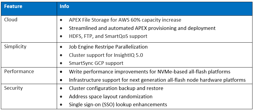
We’ll be taking a deeper look at these new features and functionality in blog articles over the course of the next few weeks.
Meanwhile, the new OneFS 9.7 code is available on the Dell Support site, as both an upgrade and reimage file, allowing both installation and upgrade of this new release.

PowerScale Platform Update
Thu, 07 Dec 2023 00:51:33 -0000
|Read Time: 0 minutes
In this article, we’ll take a quick peek at the new PowerScale Hybrid H700/7000 and Archive A300/3000 hardware platforms that were released last month. So, the current PowerScale platform family hierarchy is as follows:
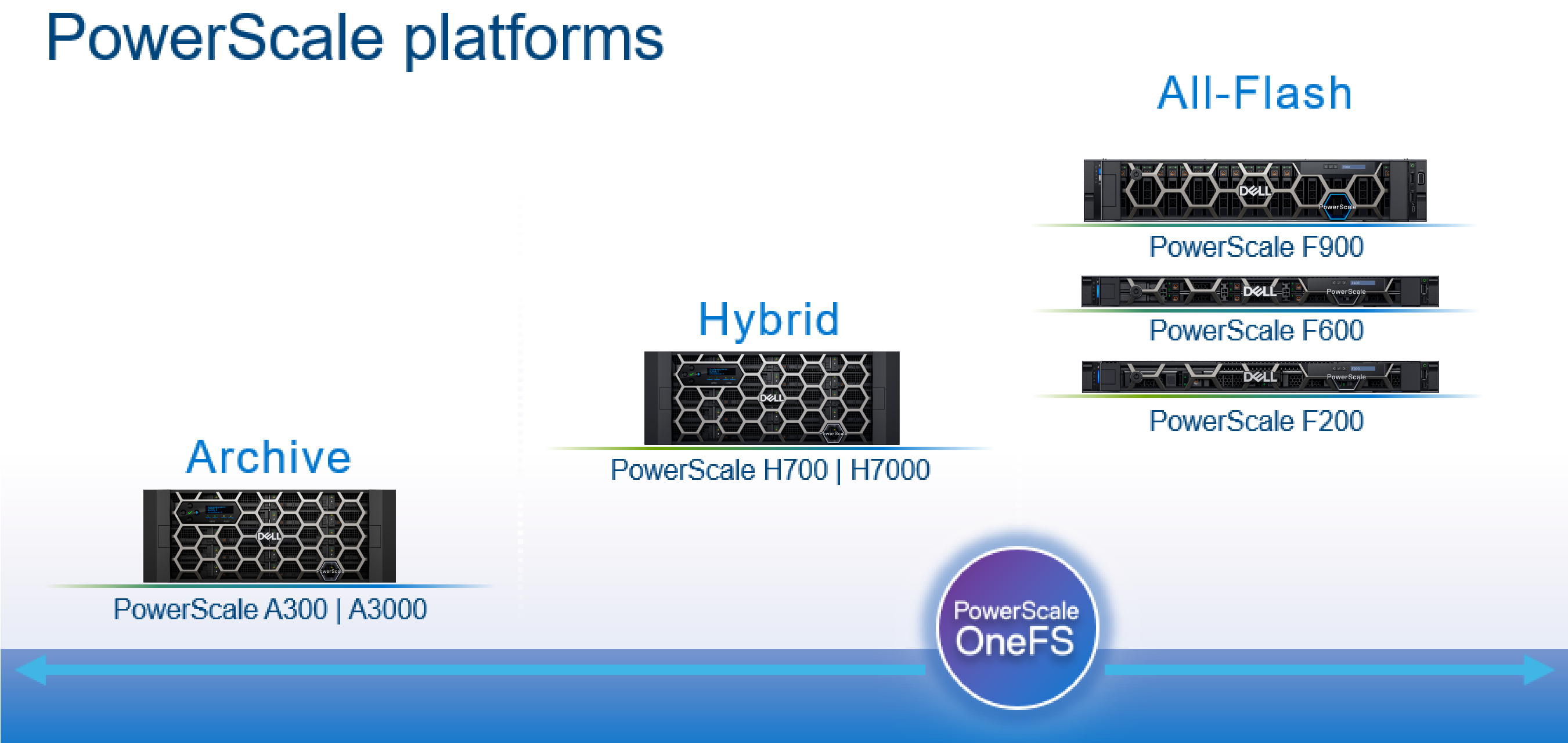
Here’s the lowdown on the new additions to the hardware portfolio:
Model | Tier | Drive per Chassis & Drives | Max Chassis Capacity (16TB HDD) | CPU per Node | Memory per Node | Network |
H700 | Hybrid/Utility | Standard: 60 x 3.5” HDD | 960TB | CPU: 2.9Ghz, 16c | Mem: 384GB | FE: 100GbE BE: 100GbE or IB |
H7000 | Hybrid/Utility | Deep: 80 x 3.5” HDD | 1280TB | CPU: 2.9Ghz, 16c | Mem: 384GB | FE: 100GbE BE: 100GbE or IB |
A300 | Archive | Standard: 60 x 3.5” HDD | 960TB | CPU: 1.9Ghz, 6c | Mem: 96GB | FE: 25GbE BE: 25GbE or IB |
A3000 | Archive | Deep: 80 x 3.5” HDD | 1280TB | CPU: 1.9Ghz, 6c | Mem: 96GB | FE: 25GbE BE: 25GbE or IB |
The PowerScale H700 provides performance and value to support demanding file workloads. With up to 960 TB of HDD per chassis, the H700 also includes inline compression and deduplication capabilities to further extend the usable capacity.
The PowerScale H7000 is a versatile, high performance, and high capacity hybrid platform with up to 1280 TB per chassis. The deep chassis based H7000 is an ideal to consolidate a range of file workloads on a single platform. The H7000 includes inline compression and deduplication capabilities.
On the active archive side, the PowerScale A300 combines performance, near-primary accessibility, value, and ease of use. The A300 provides between 120 TB to 960 TB per chassis and scales to 60 PB in a single cluster. The A300 includes inline compression and deduplication capabilities.
PowerScale A3000: is an ideal solution for high performance, high density, and deep archive storage that safeguards data efficiently for long-term retention. The A3000 stores up to 1280 TB per chassis and scales to north of 80 PB in a single cluster. The A3000 also includes inline compression and deduplication.
These new H700/7000 and A300/3000 nodes require OneFS 9.2.1, and can be seamlessly added to an existing cluster. The benefits of offering the full complement of OneFS data services includes: snapshots, replication, quotas, analytics, data reduction, load balancing, and local and cloud tiering. All also contain SSD.
Unlike the all-flash PowerScale F900, F600, and F200 stand-alone nodes, which required a minimum of 3 nodes to form a cluster, a single chassis of 4 nodes is required to create a cluster which offers support for both InfiniBand and Ethernet backend network connectivity.
Each F700/7000 and A300/3000 chassis contains four compute modules (one per node), and five drive containers, or sleds, per node. These sleds occupy bays in the front of each chassis, with a node’s drive sleds stacked vertically:
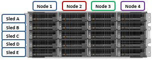
The drive sled is a tray which slides into the front of the chassis and contains between three and four 3.5 inch drives in an H700/0 or A300/0, depending on the drive size and configuration of the particular node. Both regular hard drives or self-encrypting drives (SEDs) are available in 2,4, 8, 12, and 16TB capacities.
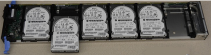
Each drive sled has a white ‘not safe to remove’ LED on its front top left, as well as a blue power/activity LED, and an amber fault LED.
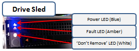
The compute modules for each node are housed in the rear of the chassis, and contain CPU, memory, networking, and SSDs, and power supplies. Nodes 1 & 2 are a node pair, as are nodes 3 & 4. Each node-pair shares a mirrored journal and two power supplies.
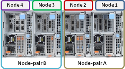
Here’s the detail of an individual compute module, which contains a multi core Cascade Lake CPU, memory, M2 flash journal, up to two SSDs for L3 cache, six DIMM channels, front end 40/100 or 10/25 Gb ethernet, 40/100 or 10/25 Gb ethernet or Infiniband, an ethernet management interface, and power supply and cooling fans:
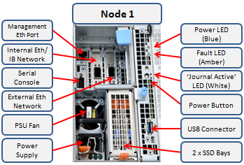
Of particular interest is the ‘journal active’ LED, which is displayed as a white ‘hand icon’. When this is illuminated, it indicates that the mirrored journal is actively vaulting.

A node’s compute module should not be removed from the chassis while this while LED is lit!
On the front of each chassis is an LCD front panel control with back-lit buttons and 4 LED Light Bar Segments - 1 per Node. These LEDs typically display blue for normal operation or yellow to indicate a node fault. This LCD display is hinged so it can be swung clear of the drive sleds for non-disruptive HDD replacement, for example.
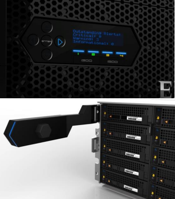
So, in summary, the new Gen6 hardware delivers:
- More Power
- More cores, more memory and more cache
- A300/3000 up to 2x faster than previous generation (A200/2000)
- More Choice
- 100GbE, 25GbE and Infiniband options for cluster interconnect
- Node compatibility for all hybrid and archive nodes
- 30TB to 320TB per rack unit
- More Value
- Inline data reduction across the PowerScale family
- Lowest $/GB and most density among comparable solutions

Harnessing Artificial Intelligence for Safety and Security
Wed, 22 Nov 2023 00:17:57 -0000
|Read Time: 0 minutes
In the rapidly evolving landscape of technology, we find ourselves on the brink of a major technological leap with the integration of artificial intelligence (AI) into our daily lives. The potential impact of AI on the global economy is staggering, with forecasts predicting a whopping $13 trillion contribution. While the idea of AI isn't entirely new in the security sector which has previously employed analytics to monitor and report pixel changes in CCTV footage, the integration of AI technologies such as machine and deep learning has opened up a world of possibilities. One particularly rich source of data that organizations are eager to harness is video data, which is pivotal in a variety of use cases including operational improvements for retail, marketing strategies, and the enhancement of overall customer experiences.
Industries across the board are exploring AI's ability to enhance business efficiency, underscored by a whopping 63% of enterprise clients considering their security data as mission critical. That said, the success of AI deployments hinges on the collection and storage of data. AI models thrive on large, diverse datasets to achieve effectiveness and accuracy. For instance, when analyzing traffic patterns within a city, having access to comprehensive data spanning multiple seasons allows for more accurate planning. This necessity has led to the emergence of exceptionally large storage volumes to cater to AI's insatiable appetite for data.
A considerable portion of data – approximately 80% – collected by organizations is unstructured, including video data. Data scientists are faced with the arduous task of mapping this unstructured data into their models, thanks in part to the fragmented nature of security solutions. Shockingly, over 79% of a data scientists’ time is consumed by data wrangling and collection rather than actual data analysis due to siloed data storage. Complex scenarios involving thousands of cameras pointed at different targets further complicate the application of AI models to this data.
Recent discussions in the field of AI have introduced the concept of ‘Data Fuzion,’ which underscores the importance of consolidating and harmonizing data, overcoming the current infrastructure's obstacles, and making data more accessible and usable for data science applications in the security industry. There is a significant divide between the potential for data science solutions to drive business outcomes and the actual implementation, largely attributed to – as previously mentioned – the fragmented, siloed nature of data storage and the scarcity of in-house data science expertise.
The AI solutions available today in the security domain often come as black box offerings with pre-programmed models, however end-users are increasingly seeking low- or no-code AI tools that allow them to tailor and modify models to meet their specific organizational needs. This shift enables organizations to fine-tune AI to their precise requirements, further optimizing business outcomes. Additionally, the rise of cloud computing has presented budgetary challenges as organizations are increasingly paying for data access, leading to a trend of cloud repatriation – moving data back to on-premises environments to better manage costs and reduce latency in real-time applications.
AI is transforming the way organizations protect not only their external security but also their internal data. Dell Technologies, for example, offers a solution known as Ransomware Defender within its unstructured data offerings, an AI-based detection tool which identifies anomalies and takes action when malicious actors attempt to encrypt or delete data by modeling typical behaviors and sounding alarms when suspicious activities occur. Check out the Dell Technologies cyber security solution page for more information.
To fully harness the power of AI and navigate these complex data landscapes, organizations are turning to single-volume unstructured data solutions that embody the concept of ‘Data Fuzion.’ Dell Technologies Unstructured Data Solutions, with their petabyte-scale single-volume architecture, offer not only the ability to support this burgeoning workload but also robust cyber protection and multi-cloud capabilities. In this way, organizations can chart a seamless path towards AI adoption while ensuring data-driven security and efficiency. Visit the Dell Technologies PowerScale solutions page to learn more.
Resources
Authors: Mordekhay Shushan | Safety and Security Solution Architect & Brian Stonge | Business Development Manager, Video Safety and Security

OneFS WebUI Single Sign-on Management and Troubleshooting
Thu, 16 Nov 2023 20:53:16 -0000
|Read Time: 0 minutes
Earlier in this series, we took a look at the architecture of the new OneFS WebUI SSO functionality. Now, we move on to its management and troubleshooting.
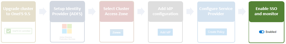
As we saw in the previous article, once the IdP and SP are configured, a cluster admin can enable SSO per access zone using the OneFS WebUI by navigating to Access > Authentication providers > SSO. From here, select the desired access zone and click the ‘Enable SSO’ toggle:
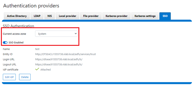
Or from the OneFS CLI using the following syntax:
# isi auth sso settings modify --sso-enabled 1
Once complete, the SSO configuration can be verified from a client web browser by browsing to the OneFS login screen. If all is operating correctly, redirection to the ADFS login screen will occur. For example:
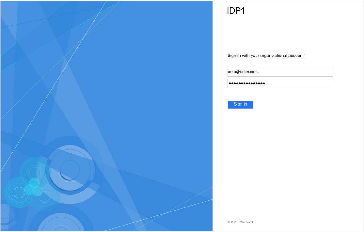
After successful authentication with ADFS, cluster access is granted and the browser session is redirected back to the OneFS WebUI .
In addition to the new SSO WebUI pages, OneFS 9.5 also adds a subcommand to the ‘isi auth’ command set for configuring SSO from the CLI. This new syntax includes:
- isi auth sso idps
- isi auth sso settings
- isi auth sso sp
With these, you can use the following procedure to configure and enable SSO using the OneFS command line.
1. Define the ADFS instance in OneFS.
Enter the following command to create the IdP account:
# isi auth ads create <domain_name> <user> --password=<password> ...
where:
Attribute | Description |
<domain_name> | Fully qualified Active Directory domain name that identifies the ADFS server. For example, idp1.isilon.com. |
<user> | The user account that has permission to join machines to the given domain. |
<password> | The password for <user>. |
2. Next, add the IdP to the pertinent OneFS zone. Note that each of a cluster’s access zone(s) must have an IdP configured for it. The same IdP can be used for all the zones, but each access zone must be configured separately.
# isi zone zones modify --add-auth-providers
For example:
# isi zone zones modify system --add-auth-providers=lsa-activedirectoryprovider:idp1.isilon.com
3. Verify that OneFS can find users in Active Directory.
# isi auth users view idp1.isilon.com\\<username>
In the output, ensure that an email address is displayed. If not, return to Active Directory and assign email addresses to users.
4. Configure the OneFS hostname for SAML SSO.
# isi auth sso sp modify --hostname=<name>
Where <name> is the name that SAML SSO can use to represent the OneFS cluster to ADFS. SAML redirects clients to this hostname.
5. Obtain the ADFS metadata and store it under /ifs on the cluster.
In the following example, an HTTPS GET request is issued using the 'curl' utility to obtain the metadata from the IDP and store it under /ifs on the cluster.
# curl -o /ifs/adfs.xml https://idp1.isilon.com/FederationMetadata/2007-06/ FederationMetadata.xml
6. Create the IdP on OneFS using the ‘metadata-location’ path for the xml file in the previous step.
# isi auth sso idps create idp1.isilon.com --metadata-location="/ifs/adfs.xml"
7. Enable SSO:
# isi auth sso settings modify --sso-enabled=yes -–zone <zone>
Use the following syntax to view the IdP configuration:
# isi auth sso idps view <idp_ID>
For example:
# isi auth sso idps view idp
ID: idp
Metadata Location: /ifs/adfs.xml
Entity ID: https://dns.isilon.com/adfs/services/trust
Login endpoint of the IDP
URL: https://dns.isilon.com/adfs/ls/
Binding: wrn:oasis:names:tc:SAML:2.0:bidings:HTTP-Redirect
Logout endpoint of the IDP
URL: https://dns.isilon.com/adfs/ls/
Binding: wrn:oasis:names:tc:SAML:2.0:bidings:HTTP-Redirect
Response URL: -
Type: metadata
Signing Certificate: -
        Path:
        Issuer: CN-ADFS Signing – dns.isilon.com
        Subject: CN-ADFS Signing – dns.isilon.com
        Not Before: 2023-02-02T22:22:00
        Not After: 2024-02-02T22:22:00
        Status: valid
Value and Type
        Value: -----BEGIN CERTIFICATE-----
MITC9DCCAdygAwIBAgIQQQQc55appr1CtfPNj5kv+DANBgkqhk1G9w8BAQsFADA2
<snip>
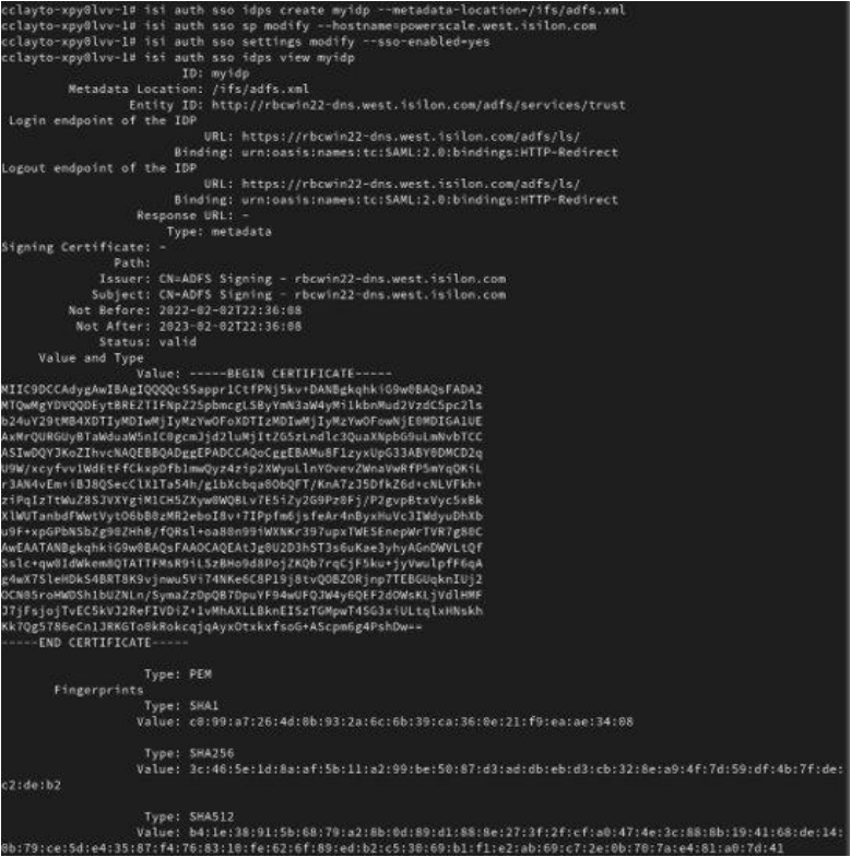
Troubleshooting
If the IdP and/or SP Signing certificate happens to expire, users will be unable to login to the cluster with SSO and an error message will be displayed on the login screen.
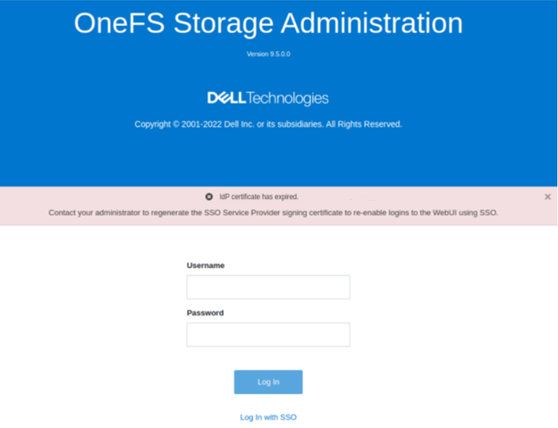
In this example, the IdP certificate has expired, as described in the alert message. When this occurs, a warning is also displayed on the SSO Authentication page, as shown here:
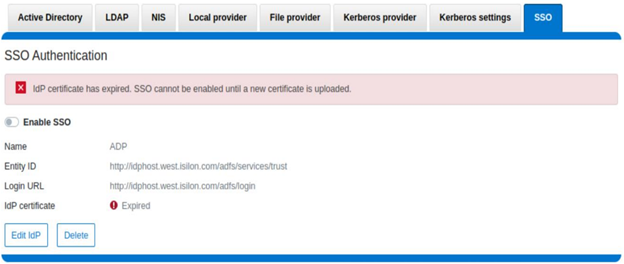
To correct this, download either a new signing certificate from the identity provider or a new metadata file containing the IdP certificate details. When this is complete, you can then update the cluster’s IdP configuration by uploading the XML file or the new certificate.
Similarly, if the SP certificate has expired, the following notification alert is displayed upon attempted login:
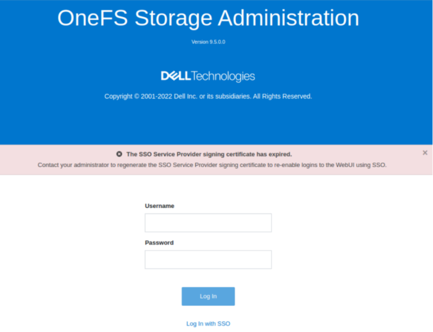
The following error message is also displayed on the WebUI SSO tab, under Access > Authentication providers > SSO, along with a link to regenerate the metadata file:
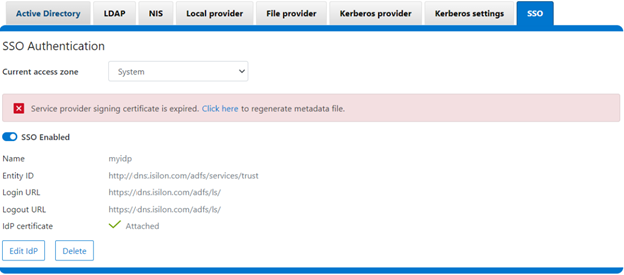
The expired SP signing key and certificate can also be easily regenerated from the OneFS CLI:
# isi auth sso sp signing-key rekey
This command will delete any existing signing key and certificate and replace them with a newly generated signing key and certificate. Make sure the newly generated certificate is added to the IDP to ensure that the IDP can verify messages sent from the cluster. Are you sure?  (yes/[no]):   yes
# isi auth sso sp signing-key dump
-----BEGIN CERIFICATE-----
MIIE6TCCAtGgAwIBAgIJAP30nSyYUz/cMA0GCSqGSIb3DQEBCwUAMCYxJDAiBgNVBAMMG1Bvd2VyU2NhbGUgU0FNTCBTaWduaWSnIEtleTAeFw0yMjExMTUwMzU0NTFaFw0yMzExMTUwMzU0NTFaMCYxJDAiBgNVBAMMG1Bvd2VyU2NhbGUgU0FNTCBTaWduaWSnIEtleTCCAilwDQYJKoZIhvcNAQEBBQADggIPADCCAgoCggIBAMOOmYJ1aUuxvyH0nbUMurMbQubgtdpVBevy12D3qn+x7rgym8/v50da/4xpMmv/zbE0zJ0IVbWHZedibtQhLZ1qRSY/vBlaztU/nA90XQzXMnckzpcunOTG29SMO3x3Ud4*fqcP4sKhV
<snip>
When it is regenerated, either the XML file or certificate can be downloaded, and the cluster configuration updated by either metadata download or manual copy:
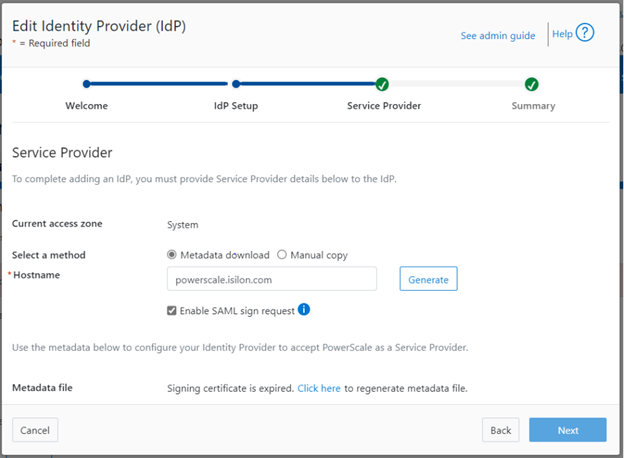
Finally, upload the SP details back to the identity provider.
For additional troubleshooting of OneFS SSO and authentication issues, there are some key log files to check. These include:
Log file | Information |
/var/log/isi_saml_d.log | SAML specific log messages logged by isi_saml_d. |
/var/log/apache2/webui_httpd_error.log | WebUI error messages including some SAML errors logged by the WebUI HTTP server. |
/var/log/jwt.log | Errors related to token generation logged by the JWT service. |
/var/log/lsassd.log | General authentication errors logged by the ‘lsassd’ service, such as failing to lookup users by email. |
Author: Nick Trimbee

OneFS NFS Locking and Reporting – Part 2
Mon, 13 Nov 2023 17:58:49 -0000
|Read Time: 0 minutes
In the previous article in this series, we took a look at the new NFS locks and waiters reporting CLI command set and API endpoints. Next, we turn our attention to some additional context, caveats, and NFSv3 lock removal.
Before the NFS locking enhancements in OneFS 9.5, the legacy CLI commands were somewhat inefficient. Their output also included other advisory domain locks such as SMB, which made the output more difficult to parse. The table below maps the new 9.5 CLI commands (and corresponding handlers) to the old NLM syntax.
Type / Command set | OneFS 9.5 and later | OneFS 9.4 and earlier |
Locks | isi nfs locks | isi nfs nlm locks |
Sessions | isi nfs nlm sessions | isi nfs nlm sessions |
Waiters | isi nfs locks waiters | isi nfs nlm locks waiters |
Note that the isi_classic nfs locks and waiters CLI commands have also been deprecated in OneFS 9.5.
When upgrading to OneFS 9.5 or later from a prior release, the legacy platform API handlers continue to function through and post upgrade. Thus, any legacy scripts and automation are protected from this lock reporting deprecation. Additionally, while the new platform API handlers will work in during a rolling upgrade in mixed-mode, they will only return results for the nodes that have already been upgraded (‘high nodes’).
Be aware that the NFS locking CLI framework does not support partial responses. However, if a node is down or the cluster has a rolling upgrade in progress, the alternative is to query the equivalent platform API endpoint instead.
Performance-wise, on very large busy clusters, there is the possibility that the lock and waiter CLI commands’ output will be sluggish. In such instances, the --timeout flag can be used to increase the command timeout window. Output filtering can also be used to reduce number of locks reported.
When a lock is in a transition state, there is a chance that it may not have/report a version. In these instances, the Version field will be represented as —. For example:
# isi nfs locks list -v
Client: 1/TMECLI1:487722/10.22.10.250
Client ID: 487722351064074
LIN: 4295164422
Path: /ifs/locks/nfsv3/10.22.10.250_1
Lock Type: exclusive
Range: 0, 92233772036854775807
Created: 2023-08-18T08:03:52
Version: -
---------------------------------------------------------------
Total: 1
This behavior should be experienced very infrequently. However, if it is encountered, simply execute the CLI command again, and the lock version should be reported correctly.
When it comes to troubleshooting NFSv3/NLM issues, if an NFSv3 client is consistently experiencing NLM_DENIED or other lock management issues, this is often a result of incorrectly configured firewall rules. For example, take the following packet capture (PCAP) excerpt from an NFSv4 Linux client:
21 08:50:42.173300992 10.22.10.100 → 10.22.10.200 NLM 106 V4 LOCK Reply (Call In 19) NLM_DENIED
Often, the assumption is that only the lockd or statd ports on the server side of the firewall need to be opened and that the client always makes that connection that way. However, this is not the case. Instead, the server will continually respond with a ‘let me get back to you’, then later reconnect to the client. As such, if the firewall blocks access to rcpbind on the client and/or lockd or statd on the client, connection failures will likely occur.
Occasionally, it does become necessary to remove NLM locks and waiters from the cluster. Traditionally, the isi_classic nfs clients rm command was used, however that command has limitations and is fully deprecated in OneFS 9.5 and later. Instead, the preferred method is to use the isi nfs nlm sessions CLI utility in conjunction with various other ancillary OneFS CLI commands to clear problematic locks and waiters.
Note that the isi nfs nlm sessions CLI command, available in all current OneFS version, is Zone-Aware. The output formatting is seen in the output for the client holding the lock as it now shows the Zone ID number at the beginning. For example:
4/tme-linux1/10.22.10.250 This represents:
Zone ID 4 / Client tme-linux1 / IP address of cluster node holding the connection.
A basic procedure to remove NLM locks and waiters from a cluster is as follows:
1. List the NFS locks and search for the pertinent filename.
In OneFS 8.5 and later, the locks list can be filtered using the --path argument.
# isi nfs locks list --path=<path> | grep <filename>
Be aware that the full path must be specified, starting with /ifs. There is no partial matching or substitution for paths in this command set.
For OneFS 9.4 and earlier, the following CLI syntax can be used:
# isi_for_array -sX 'isi nfs nlm locks list | grep <filename>'
2. List the lock waiters associated with the same filename using |grep.
For OneFS 8.5 and later, the waiters list can also be filtered using the --path syntax:
# isi nfs locks waiters –path=<path> | grep <filename>
With OneFS 9.4 and earlier, the following CLI syntax can be used:
# isi_for_array -sX 'isi nfs nlm locks waiters |grep -i <filename>'
3. Confirm the client and logical inode number (LIN) being waited upon.
This can be accomplished by querying the efs.advlock.failover.lock_waiters sysctrl. For example:
# isi_for_array -sX 'sysctl efs.advlock.failover.lock_waiters'

[truncated output]
 ...
 client = { '4/tme-linux1/10.20.10.200’, 0x26593d37370041 }
 ...
resource = 2:df86:0218
Note that for sanity checking, the isi get -L CLI utility can be used to confirm the path of a file from its LIN:
isi get -L <LIN>
4. Remove the unwanted locks which are causing waiters to stack up.
Keep in mind that the isi nfs nlm sessions command syntax is access zone-aware.
List the access zones by their IDs.
# isi zone zones list -v | grep -iE "Zone ID|name"
Once the desired zone ID has been determined, the isi_run -z CLI utility can be used to specify the appropriate zone in which to run the isi nfs nlm sessions commands:
# isi_run -z 4 -l root
Next, the isi nfs nlm sessions delete CLI command will remove the specific lock waiter which is causing the issue. The command syntax requires specifying the client hostname and node IP of the node holding the lock.
# isi nfs nlm sessions delete –-zone <AZ_zone_ID> <hostname> <cluster-ip>
For example:
# isi nfs nlm sessions delete –zone 4 tme-linux1 10.20.10.200
 Are you sure you want to delete all NFSv3 locks associated with client tme-linux1 against cluster IP 10.20.10.100? (yes/[no]): yes
5. Repeat the commands in step 1 to confirm that the desired NLM locks and waiters have been successfully culled.
BEFORE applying the process....
 # isi_for_array -sX 'isi nfs nlm locks list |grep JUN'
 TME-1: 4/tme-linux1/192.168.2.214  /ifs/tmp/TME/sequences/mncr_fabjob_seq_file_27JUN2017
 TME-1: 4/ tme-linux1/192.168.2.214  /ifs/tmp/TME/sequences/mncr_fabjob_seq_file_28JUN2017
 TME-2: 4/ tme-linux1/192.168.2.214  /ifs/tmp/TME/sequences/mncr_fabjob_seq_file_27JUN2017
 TME-2: 4/ tme-linux1/192.168.2.214  /ifs/tmp/TME/sequences/mncr_fabjob_seq_file_28JUN2017
 TME-3: 4/ tme-linux1/192.168.2.214  /ifs/tmp/TME/sequences/mncr_fabjob_seq_file_27JUN2017
 TME-3: 4/ tme-linux1/192.168.2.214  /ifs/tmp/TME/sequences/mncr_fabjob_seq_file_28JUN2017
 TME-4: 4/ tme-linux1/192.168.2.214  /ifs/tmp/TME/sequences/mncr_fabjob_seq_file_27JUN2017
 TME-4: 4/ tme-linux1/192.168.2.214  /ifs/tmp/TME/sequences/mncr_fabjob_seq_file_28JUN2017
 TME-5: 4/ tme-linux1/192.168.2.214  /ifs/tmp/TME/sequences/mncr_fabjob_seq_file_27JUN2017
 TME-5: 4/ tme-linux1/192.168.2.214  /ifs/tmp/TME/sequences/mncr_fabjob_seq_file_28JUN2017
 TME-6: 4/ tme-linux1/192.168.2.214  /ifs/tmp/TME/sequences/mncr_fabjob_seq_file_27JUN2017
 TME-6: 4/ tme-linux1/192.168.2.214  /ifs/tmp/TME/sequences/mncr_fabjob_seq_file_28JUN2017


 # isi_for_array -sX 'isi nfs nlm locks waiters |grep -i JUN'
 TME-1: 4/ tme-linux1/192.168.2.214  /ifs/tmp/TME/sequences/mncr_fabjob_seq_file_28JUN2017
 TME-1: 4/ tme-linux1/192.168.2.214  /ifs/tmp/TME/sequences/mncr_fabjob_seq_file_28JUN2017
 TME-2 exited with status 1
 TME-3 exited with status 1
 TME-4 exited with status 1
 TME-5 exited with status 1
 TME-6 exited with status 1
AFTER...
TME-1# isi nfs nlm sessions delete --hostname= tme-linux1 --cluster-ip=192.168.2.214
 Are you sure you want to delete all NFSv3 locks associated with client tme-linux1 against cluster IP 192.168.2.214? (yes/[no]): yes
 TME-1#
 TME-1#
 TME-1# isi_for_array -sX 'sysctl efs.advlock.failover.locks |grep 2:ce75:0319'
 TME-1 exited with status 1
 TME-2 exited with status 1
 TME-3 exited with status 1
 TME-4 exited with status 1
 TME-5 exited with status 1
 TME-6 exited with status 1
 TME-1#
 TME-1# isi_for_array -sX 'isi nfs nlm locks list |grep -i JUN'
 TME-1 exited with status 1
 TME-2 exited with status 1
 TME-3 exited with status 1
 TME-4 exited with status 1
 TME-5 exited with status 1
 TME-6 exited with status 1
 TME-1#
 TME-1# isi_for_array -sX 'isi nfs nlm locks waiters |grep -i JUN'
 TME-1 exited with status 1
 TME-2 exited with status 1
 TME-3 exited with status 1
 TME-4 exited with status 1
 TME-5 exited with status 1
 TME-6 exited with status 1

OneFS NFS Locking
Mon, 13 Nov 2023 17:56:59 -0000
|Read Time: 0 minutes
Included among the plethora of OneFS 9.5 enhancements is an updated NFS lock reporting infrastructure, command set, and corresponding platform API endpoints. This new functionality includes enhanced listing and filtering options for both locks and waiters, based on NFS major version, client, LIN, path, creation time, etc. But first, some backstory.
The ubiquitous NFS protocol underwent some fundamental architectural changes between its versions 3 and 4. One of the major differences concerns the area of file locking.
NFSv4 is the most current major version of the protocol, natively incorporating file locking and thereby avoiding the need for any additional (and convoluted) RPC callback mechanisms necessary with prior NFS versions. With NFSv4, locking is built into the main file protocol and supports new lock types, such as range locks, share reservations, and delegations/oplocks, which emulate those found in Window and SMB.
File lock state is maintained at the server under a lease-based model. A server defines a single lease period for all states held by an NFS client. If the client does not renew its lease within the defined period, all states associated with the client's lease may be released by the server. If released, the client may either explicitly renew its lease or simply issue a read request or other associated operation. Additionally, with NFSv4, a client can elect whether to lock the entire file or a byte range within a file.
In contrast to NFSv4, the NFSv3 protocol is stateless and does not natively support file locking. Instead, the ancillary Network Lock Manager (NLM) protocol supplies the locking layer. Since file locking is inherently stateful, NLM itself is considered stateful. For example, when an NFSv3 filesystem mounted on an NFS client receives a request to lock a file, it generates an NLM remote procedure call instead of an NFS remote procedure call.
The NLM protocol itself consists of remote procedure calls that emulate the standard UNIX file control (fcntl) arguments and outputs. Because a process blocks waiting for a lock that conflicts with another lock holder – also known as a ‘blocking lock’ – the NLM protocol has the notion of callbacks from the file server to the NLM client to notify that a lock is available. As such, the NLM client sometimes acts as an RPC server in order to receive delayed results from lock calls.
Attribute | NFSv3 | NFSv4 |
State | Stateless - A client does not technically establish a new session if it has the correct information to ask for files and so on. This allows for simple failover between OneFS nodes using dynamic IP pools. | Stateful - NFSv4 uses sessions to handle communication. As such, both client and server must track session state to continue communicating. |
Presentation | User and Group info is presented numerically - Client and Server communicate user information by numeric identifiers, allowing the same user to appear as different names between client and server. | User and Group info is presented as strings - Both the client and server must resolve the names of the numeric information stored. The server must look up names to present while the client must remap those to numbers on its end. |
Locking | File Locking is out of band - uses NLM to perform locks. This requires the client to respond to RPC messages from the server to confirm locks have been granted, etc. | File Locking is in band - No longer uses a separate protocol for file locking, instead making it a type of call that is usually compounded with OPENs, CREATEs, or WRITEs. |
Transport | Can run over TCP or UDP - This version of the protocol can run over UDP instead of TCP, leaving handling of loss and retransmission to the software instead of the operating system. We always recommend using TCP. | Only supports TCP - Version 4 of NFS has left loss and retransmission up to the underlying operating system. Can batch a series of calls in a single packet, allowing the server to process all of them and reply at the end. This is used to reduce the number of calls involved in common operations. |
Since NFSv3 is stateless, it requires more complexity to recover from failures like client and server outages and network partitions. If an NLM server crashes, NLM clients that are holding locks must reestablish them on the server when it restarts. The NLM protocol deals with this by having the status monitor on the server send a notification message to the status monitor of each NLM client that was holding locks. The initial period after a server restart is known as the grace period, during which only requests to reestablish locks are granted. Thus, clients that reestablish locks during the grace period are guaranteed to not lose their locks.
When an NLM client crashes, ideally any locks it was holding at the time are removed from the pertinent NLM server(s). The NLM protocol handles this by having the status monitor on the client send a message to each server's status monitor once the client reboots. The client reboot indication informs the server that the client no longer requires its locks. However, if the client crashes and fails to reboot, the client's locks will persist indefinitely. This is undesirable for two primary reasons: Resources are indefinitely leaked. Eventually, another client will want to get a conflicting lock on at least one of the files the crashed client had locked and, as a result, the other client is postponed indefinitely.
Therefore, having NFS server utilities to swiftly and accurately report on lock and waiter status and utilities to clear NFS lock waiters is highly desirable for administrators – particularly on clustered storage architectures.
Prior to OneFS 9.5, the old NFS locking CLI commands were somewhat inefficient and also showed other advisory domain locks, which rendered the output somewhat confusing. The following table shows the new CLI commands (and corresponding handlers) which replace the older NLM syntax.
Type / Command set | OneFS 9.4 and earlier | OneFS 9.5 |
Locks | isi nfs nlm locks | isi nfs locks |
Sessions | isi nfs nlm sessions | isi nfs nlm sessions |
Waiters | isi nfs nlm locks waiters | isi nfs locks waiters |
In OneFS 9.5 and later, the old API handlers will still exist to avoid breaking existing scripts and automation, however the CLI command syntax is deprecated and will no longer work.
Also be aware that the isi_classic nfs locks and waiters CLI commands have also been disabled in OneFS 9.5. Attempts to run these will yield the following warning message:
# isi_classic nfs locks
This command has been disabled. Please use isi nfs for this functionality.
The new isi nfs locks CLI command output includes the following locks object fields:
Field | Description |
Client | The client host name, Frequently Qualified Domain Name, or IP |
Client_ID | The client ID (internally generated) |
Created | The UNIX Epoch time that the lock was created |
ID | The lock ID (Id necessary for platform API sorting, not shown in CLI output) |
LIN | The logical inode number (LIN) of the locked resource |
Lock_type | The type of lock (shared, exclusive, none) |
Path | Path of locked file |
Range | The byte range within the file that is locked |
Version | The NFS major version: v3, or v4 |
Note that the ISI_NFS_PRIV RBAC privilege is required in order to view the NFS locks or waiters via the CLI or PAPI. In addition to ‘root’, the cluster’s ‘SystemAdmin’ and ‘SecurityAdmin’ roles contain this privilege by default.
Additionally, the new locks CLI command sets have a default timeout of 60 seconds. If the cluster is very large, the timeout may need to be increased for the CLI command. For example:
# isi –timeout <timeout value> nfs locks list
The basic architecture of the enhanced NFS locks reporting framework is as follows:
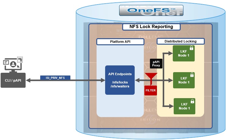
The new API handlers leverage the platform API proxy, yielding increased performance over the legacy handlers. Additionally, updated syscalls have been implemented to facilitate filtering by NFS service and major version.
Since NFSv3 is stateless, the cluster does not know when a client has lost its state unless it reconnects. For maximum safety, the OneFS locking framework (lk) holds locks forever. The isi nfs nlm sessions CLI command allows administrators to manually free NFSv3 locks in such cases, and this command remains available in OneFS 9.5 as well as prior versions. NFSv3 locks may also be leaked on delete, since a valid inode is required for lock operations. As such, lkf has a lock reaper which periodically checks for locks associated with deleted files.
In OneFS 9.5 and later, current NFS locks can be viewed with the new isi nfs locks list command. This command set also provides a variety of options to limit and format the display output. In its basic form, this command generates a basic list of client IP address and the path. For example:
# isi nfs locks list
Client                              Path
-------------------------------------------------------------------
1/TMECLI1:487722/10.22.10.250       /ifs/locks/nfsv3/10.22.10.250_1
1/TMECLI1:487722/10.22.10.250       /ifs/locks/nfsv3/10.22.10.250_2
Linux NFSv4.0 TMECLI1:487722/10.22.10.250       /ifs/locks/nfsv4/10.22.10.250_1
Linux NFSv4.0 TMECLI1:487722/10.22.10.250       /ifs/locks/nfsv4/10.22.10.250_2
-------------------------------------------------------------------
Total: 4
To include more information, the -v flag can be used to generate a verbose locks listing:
 # isi nfs locks list -v
Client: 1/TMECLI1:487722/10.22.10.250
Client ID: 487722351064074
LIN: 4295164422
Path: /ifs/locks/nfsv3/10.22.10.250_1
Lock Type: exclusive
Range: 0, 92233772036854775807
Created: 2023-08-18T08:03:52
Version: v3
---------------------------------------------------------------
Client: 1/TMECLI1:487722/10.22.10.250
Client ID: 5175867327774721
LIN: 42950335042
Path: /ifs/locks/nfsv3/10.22.10.250_1
Lock Type: exclusive
Range: 0, 92233772036854775807
Created: 2023-08-18T08:10:31
Version: v3
---------------------------------------------------------------
Client: Linux NFSv4.0 TMECLI1:487722/10.22.10.250
Client ID: 487722351064074
LIN: 429516442
Path: /ifs/locks/nfsv3/10.22.10.250_1
Lock Type: exclusive
Range: 0, 92233772036854775807
Created: 2023-08-18T08:19:48
Version: v4
---------------------------------------------------------------
Client: Linux NFSv4.0 TMECLI1:487722/10.22.10.250
Client ID: 487722351064074
LIN: 4295426674
Path: /ifs/locks/nfsv3/10.22.10.250_2
Lock Type: exclusive
Range: 0, 92233772036854775807
Created: 2023-08-18T08:17:02
Version: v4
---------------------------------------------------------------
Total: 4
The previous syntax returns more detailed information for each lock, including client ID, LIN, path, lock type, range, created date, and NFS version.
The lock listings can also be filtered by client or client-id. Note that the --client option must be the full name in quotes:
# isi nfs locks list --client="full_name_of_client/IP_address" -v
For example:
# isi nfs locks list --client="1/TMECLI1:487722/10.22.10.250" -v
Client: 1/TMECLI1:487722/10.22.10.250
Client ID: 5175867327774721
LIN: 42950335042
Path: /ifs/locks/nfsv3/10.22.10.250_1
Lock Type: exclusive
Range: 0, 92233772036854775807
Created: 2023-08-18T08:10:31
Version: v3
Additionally, be aware that the CLI does not support partial names, so the full name of the client must be specified.
Filtering by NFS version can be helpful when attempting to narrow down which client has a lock. For example, to show just the NFSv3 locks:
# isi nfs locks list --version=v3
Client                              Path
-------------------------------------------------------------------
1/TMECLI1:487722/10.22.10.250       /ifs/locks/nfsv3/10.22.10.250_1
1/TMECLI1:487722/10.22.10.250       /ifs/locks/nfsv3/10.22.10.250_2
-------------------------------------------------------------------
Total: 2
Note that the –-version flag supports both v3 and nlm as arguments and will return the same v3 output in either case. For example:
# isi nfs locks list --version=nlm
Client                              Path
-------------------------------------------------------------------
1/TMECLI1:487722/10.22.10.250       /ifs/locks/nfsv3/10.22.10.250_1
1/TMECLI1:487722/10.22.10.250       /ifs/locks/nfsv3/10.22.10.250_2
-------------------------------------------------------------------
Total: 2
Filtering by LIN or path is also supported. For example, to filter by LIN:
# isi nfs locks list --lin=42950335042 -v
Client: 1/TMECLI1:487722/10.22.10.250
Client ID: 5175867327774721
LIN: 42950335042
Path: /ifs/locks/nfsv3/10.22.10.250_1
Lock Type: exclusive
Range: 0, 92233772036854775807
Created: 2023-08-18T08:10:31
Version: v3
Or by path:
# isi nfs locks list --path=/ifs/locks/nfsv3/10.22.10.250_2
 -v
Client: Linux NFSv4.0 TMECLI1:487722/10.22.10.250
Client ID: 487722351064074
LIN: 4295426674
Path: /ifs/locks/nfsv3/10.22.10.250_2
Lock Type: exclusive
Range: 0, 92233772036854775807
Created: 2023-08-18T08:17:02
Version: v4
Be aware that the full path must be specified, starting with /ifs. There is no partial matching or substitution for paths in this command set.
Filtering can also be performed by creation time, for example:
# isi nfs locks list --created=2023-08-17T09:30:00 -v
Note that when filtering by created, the output will include all locks that were created before or at the time provided.
The —limits argument can be used to curtail the number of results returned, and limits can be used in conjunction with all other query options. For example, to limit the output of the NFSv4 locks listing to one lock:
# isi nfs locks list -–version=v4 --limit=1
Note that limit can be used with the range of query types.
The filter options are mutually exclusive with the exception of version. Note that version can be used with any of the other filter options. For example, filtering by both created and version.
This can be helpful when troubleshooting and trying to narrow down results.
In addition to locks, OneFS 9.5 also provides the isi nfs locks waiters CLI command set. Note that waiters are specific to NFSv3 clients, and the CLI reports any v3 locks that are pending and not yet granted.
Since NFSv3 is stateless, a cluster does not know when a client has lost its state unless it reconnects. For maximum safety, lk holds locks forever. The isi nfs nlm command allows administrators to manually free locks in such cases. Locks may also be leaked on delete, since a valid inode is required for lock operations. Thus, lkf has a lock reaper which periodically checks for locks associated with deleted files:
# isi nfs locks waiters
The waiters CLI syntax uses a similar range of query arguments as the isi nfs locks list command set.
In addition to the CLI, the platform API can also be used to query both NFS locks and NFSv3 waiters. For example, using curl to view the waiters via the OneFS pAPI:
# curl -k -u <username>:<passwd> https://localhost:8080/platform/protocols/nfs/waiters”
{
“total” : 2,
“waiters”;
}
{
“client” : “1/TMECLI1487722/10.22.10.250”,
“client_id” : “4894369235106074”,
“created” : “1668146840”,
“id” : “1 1YUIAEIHVDGghSCHGRFHTiytr3u243567klj212-MANJKJHTTy1u23434yui-ouih23ui4yusdftyuySTDGJSDHVHGDRFhgfu234447g4bZHXhiuhsdm”,
“lin” : “4295164422”,
“lock_type” : “exclusive”
“path” : “/ifs/locks/nfsv3/10.22.10.250_1”
“range” : [0, 92233772036854775807 ],
“version” : “v3”
}
},
“total” : 1
}
Similarly, using the platform API to show locks filtered by client ID:
# curl -k -u <username>:<passwd> “https://<address>:8080/platform/protocols/nfs/locks?client=<client_ID>”
For example:
# curl -k -u <username>:<passwd> “https://localhost:8080/platform/protocols/nfs/locks?client=1/TMECLI1487722/10.22.10.250”
{
“locks”;
}
{
“client” : “1/TMECLI1487722/10.22.10.250”,
“client_id” : “487722351064074”,
“created” : “1668146840”,
“id” : “1 1YUIAEIHVDGghSCHGRFHTiytr3u243567FCUJHBKD34NMDagNLKYGHKHGKjhklj212-MANJKJHTTy1u23434yui-ouih23ui4yusdftyuySTDGJSDHVHGDRFhgfu234447g4bZHXhiuhsdm”,
“lin” : “4295164422”,
“lock_type” : “exclusive”
“path” : “/ifs/locks/nfsv3/10.22.10.250_1”
“range” : [0, 92233772036854775807 ],
“version” : “v3”
}
},
“Total” : 1
}
Note that, as with the CLI, the platform API does not support partial name matches, so the full name of the client must be specified.

OneFS SSL Certificate Creation and Renewal – Part 2
Mon, 13 Nov 2023 17:56:44 -0000
|Read Time: 0 minutes
In the initial article in this series, we took a look at the OneFS SSL architecture, plus the first two steps in the basic certificate renewal or creation flow detailed below:
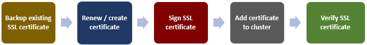
The following procedure includes options to complete a self-signed certificate replacement or renewal or to request an SSL replacement or renewal from a Certificate Authority (CA).
Signing the SSL Certificate
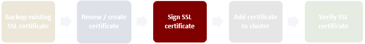
At this point, depending on the security requirements of the environment, the certificate can either be self-signed or signed by a Certificate Authority.
Self-Sign the SSL Certificate
The following CLI syntax can be used to self-sign the certificate with the key, creating a new signed certificate which, in this instance, is valid for 1 year (365 days):
# openssl x509 -req -days 365 -in server.csr -signkey server.key -out server.crt
To verify that the key matches the certificate, ensure that the output of the following CLI commands return the same md5 checksum value:
# openssl x509 -noout -modulus -in server.crt | openssl md5
# openssl rsa -noout -modulus -in server.key | openssl md5
Next, proceed to the Add certificate to cluster section of this article once this step is complete.
Use a CA to Sign the Certificate
If a CA is signing the certificate, ensure that the new SSL certificate is in x509 format and includes the entire certificate trust chain.
Note that the CA may return the new SSL certificate, the intermediate cert, and the root cert in different files. If this is the case, the PEM formatted certificate will need to be created manually.
Notably, the correct ordering is important when creating the PEM-formatted certificate. The SSL cert must be the top of the file, followed by the intermediate certificate, with the root certificate at the bottom. For example:
-----BEGIN CERTIFICATE-----
<Contents of new SSL certificate>
-----END CERTIFICATE-----
-----BEGIN CERTIFICATE-----
<Contents of intermediate certificate>
<Repeat as necessary for every intermediate certificate provided by your CA>
-----END CERTIFICATE-----
-----BEGIN CERTIFICATE-----
<Contents of root certificate file>
-----END CERTIFICATE-----
A simple method for creating the PEM formatted file from the CLI is to cat them in the correct order as follows:
# cat CA_signed.crt intermediate.crt root.crt > onefs_pem_formatted.crt
Copy the onefs_pem_formatted.crt file to /ifs/tmp and rename it to server.crt.
Note that if any of the aforementioned files are generated with a .cer extension, they should be renamed with a .crt extension instead.
The attributes and integrity of the certificate can be sanity checked with the following CLI syntax:
# openssl x509 -text -noout -in server.crt
Adding the certificate to the cluster
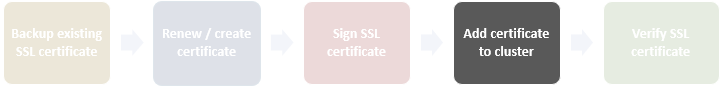
The first step in adding the certificate involves importing the new certificate and key into the cluster:
# isi certificate server import /ifs/tmp/server.crt /ifs/tmp/server.key
Next, verify that the certificate imported successfully:
# isi certificate server list -v
The following CLI command can be used to show the names and corresponding IDs of the certificates:
# isi certificate server list -v | grep -A1 "ID:"
Set the imported certificate as default:
# isi certificate settings modify --default-https-certificate=<id_of_cert_to_set_as_default>
Confirm that the imported certificate is being used as default by verifying status of Default HTTPS Certificate:
# isi certificate settings view
If there is an unused or outdated cert, it can be deleted with the following CLI syntax:
# isi certificate server delete --id=<id_of_cert_to_delete>
Next, view the new imported cert with command:
# isi certificate server view --id=<id_of_cert>
Note that ports 8081 and 8083 still use the certificate from the local directory for SSL. Follow the steps below if you want to use the new certificates for port 8081/8083:
# isi services -a isi_webui disable
# chmod 640 server.key
# chmod 640 server.crt
# isi_for_array -s 'cp /ifs/tmp/server.key /usr/local/apache2/conf/ssl.key/server.key'
# isi_for_array -s 'cp /ifs/tmp/server.crt /usr/local/apache2/conf/ssl.crt/server.crt'
isi services -a isi_webui enable
Verifying the SSL certificate
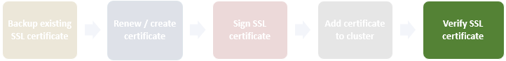
There are two methods for verifying the updated SSL certificate.:
- Via the CLI, using the openssl command as follows:
# echo QUIT | openssl s_client -connect localhost:8080
- Or via a web browser, using the following URL:
Note that where <cluster_name> is the FQDN or IP address, that’s typically used to access the cluster’s WebUI interface. The security details for the web page will contain the location and contact info, as above.
In both cases, the output includes location and contact info. For example:
Subject: C=US, ST=<yourstate>, L=<yourcity>, O=<yourcompany>, CN=isilon.example.com/emailAddress=tme@isilon.com
Additionally, OneFS provides warning of an impending certificate expiry by sending a CELOG event alert, similar to the following:
SW_CERTIFICATE_EXPIRING: X.509 certificate default is nearing expiration:
Event: 400170001
Certificate 'default' in '**' store is nearing expiration:
Note that OneFS does not attempt to automatically renew a certificate. Instead, an expiring cert has to be renewed manually, per the procedure described above.
When adding an additional certificate, the matching cert is used any time you connect to that SmartConnect name via HTTPS. If no matching certificate is found, OneFS will automatically revert to using the default self-signed certificate.

OneFS SSL Certificate Renewal – Part 1
Thu, 16 Nov 2023 04:57:00 -0000
|Read Time: 0 minutes
When using either the OneFS WebUI or platform API (pAPI), all communication sessions are encrypted using SSL (Secure Sockets Layer), also known as Transport Layer Security (TLS). In this series, we will look at how to replace or renew the SSL certificate for the OneFS WebUI.
SSL requires a certificate that serves two principal functions: It grants permission to use encrypted communication using Public Key Infrastructure and authenticates the identity of the certificate’s holder.
Architecturally, SSL consists of four fundamental components:
SSL Component | Description |
Alert | Reports issues. |
Change cipher spec | Implements negotiated crypto parameters. |
Handshake | Negotiates crypto parameters for SSL session. Can be used for many SSL/TCP connections. |
Record | Provides encryption and MAC. |
These sit in the stack as follows:
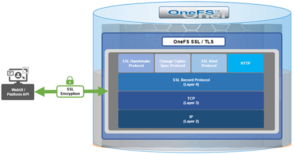
The basic handshake process begins with a client requesting an HTTPS WebUI session to the cluster. OneFS then returns the SSL certificate and public key. The client creates a session key, encrypted with the public key it is received from OneFS. At this point, the client only knows the session key. The client now sends its encrypted session key to the cluster, which decrypts it with the private key. Now, both the client and OneFS know the session key. So, finally, the session, encrypted using a symmetric session key, can be established. OneFS automatically defaults to the best supported version of SSL, based on the client request.
A PowerScale cluster initially contains a self-signed certificate, which can be used as-is or replaced with a third-party certificate authority (CA)-issued certificate. If the self-signed certificate is used upon expiry, it must be replaced with either a third-party (public or private) CA-issued certificate or another self-signed certificate that is generated on the cluster. The following are the default locations for the server.crt and server.key files.
File | Location |
SSL certificate | /usr/local/apache2/conf/ssl.crt/server.crt |
SSL certificate key | /usr/local/apache2/conf/ssl.key/server.key |
The ‘isi certificate settings view’ CLI command displays all of the certificate-related configuration options. For example:
# isi certificate settings view Certificate Monitor Enabled: Yes Certificate Pre Expiration Threshold: 4W2D Default HTTPS Certificate ID: default Subject: C=US, ST=Washington, L=Seattle, O="Isilon", OU=Isilon, CN=Dell, emailAddress=tme@isilon.com Status: valid |
The above ‘certificate monitor enabled’ and ‘certificate pre expiration threshold’ configuration options govern a nightly cron job, which monitors the expiration of each managed certificate and fires a CELOG alert if a certificate is set to expire within the configured threshold. Note that the default expiration is 30 days (4W2D, which represents 4 weeks plus 2 days). The ‘ID: default’ configuration option indicates that this certificate is the default TLS certificate.
The basic certificate renewal or creation flow is as follows:
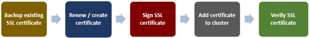
The steps below include options to complete a self-signed certificate replacement or renewal, or to request an SSL replacement or renewal from a Certificate Authority (CA).
Backing up the existing SSL certificate
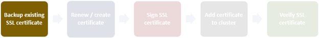
The first task is to obtain the list of certificates by running the following CLI command, and identify the appropriate one to renew:
# isi certificate server list ID Name Status Expires ------------------------------------------- eb0703b default valid 2025-10-11T10:45:52 ------------------------------------------- |
It’s always a prudent practice to save a backup of the original certificate and key. This can be easily accomplished using the following CLI commands, which, in this case, create the directory ‘/ifs/data/ssl_bkup’ directory, set the perms to root-only access, and copy the original key and certificate to it:
# mkdir -p /ifs/data/ssl_bkup # chmod 700 /ifs/data/ssl_bkup # cp /usr/local/apache24/conf/ssl.crt/server.crt /ifs/data/ssl_bkup # cp /usr/local/apache24/conf/ssl.key/server.key /ifs/data/ssl_bkup # cd !$ cd /ifs/data/ssl_bkup # ls server.crt server.key |
Renewing or creating a certificate
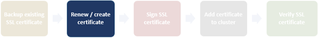
The next step in the process involves either the renewal of an existing certificate or creation of a certificate from scratch. In either case, first, create a temporary directory, for example /ifs/tmp:
| # mkdir /ifs/tmp; cd /ifs/tmp |
a) Renew an existing self-signed Certificate.
The following syntax creates a renewal certificate based on the existing ssl.key. The value of the ‘-days’ parameter can be adjusted to generate a certificate with the wanted expiration date. For example, the following command will create a one-year certificate.
| # cp /usr/local/apache2/conf/ssl.key/server.key ./ ; openssl req -new -days 365 -nodes -x509 -key server.key -out server.crt |
Answer the system prompts to complete the self-signed SSL certificate generation process, entering the pertinent information location and contact information. For example:
Country Name (2 letter code) [AU]:US
State or Province Name (full name) [Some-State]:Washington
Locality Name (eg, city) []:Seattle
Organization Name (eg, company) [Internet Widgits Pty Ltd]:Isilon
Organizational Unit Name (eg, section) []:TME
Common Name (e.g. server FQDN or YOUR name) []:isilon.com
Email Address []:tme@isilon.com
When all the information has been successfully entered, the server.csr and server.key files will be generated under the /ifs/tmp directory.
Optionally, the attributes and integrity of the certificate can be verified with the following syntax:
| # openssl x509 -text -noout -in server.crt |
Next, proceed directly to the ‘Add the certificate to the cluster’ steps in section 4 of this article.
b) Alternatively, a certificate and key can be generated from scratch, if preferred.
The following CLI command can be used to create an 2048-bit RSA private key:
# openssl genrsa -out server.key 2048 Generating RSA private key, 2048 bit long modulus ............+++++
...........................................................+++++
e is 65537 (0x10001) |
Next, create a certificate signing request:
| # openssl req -new -nodes -key server.key -out server.csr |
For example:
# openssl req -new -nodes -key server.key -out server.csr -reqexts SAN -config <(cat /etc/ssl/openssl.cnf <(printf "[SAN]\nsubjectAltName=DNS:isilon.com")) You are about to be asked to enter information that will be incorporated into your certificate request. What you are about to enter is what is called a Distinguished Name or a DN. There are quite a few fields but you can leave some blank For some fields there will be a default value, If you enter '.', the field will be left blank. ----- Country Name (2 letter code) [AU]:US State or Province Name (full name) [Some-State]:WA Locality Name (eg, city) []:Seattle Organization Name (eg, company) [Internet Widgits Pty Ltd]:Isilon Organizational Unit Name (eg, section) []:TME Common Name (e.g. server FQDN or YOUR name) []:h7001 Email Address []:tme@isilon.com Please enter the following 'extra' attributes to be sent with your certificate request A challenge password []:1234 An optional company name []: # |
Answer the system prompts to complete the self-signed SSL certificate generation process, entering the pertinent information location and contact information. Additionally, a ‘challenge password’ with a minimum of 4-bytes in length will need to be selected and entered.
As prompted, enter the information to be incorporated into the certificate request. When completed, the server.csr and server.key files will appear in the /ifs/tmp directory.
If wanted, a CSR file for a Certificate Authority, which includes Subject-Alternative-Names (SAN) can be generated. For example, additional host name entries can be added using a comma (IE. DNS:isilon.com,DNS:www.isilon.com).
In the next article, we will look at the certificate singing, addition, and verification steps of the process.

SMB Redirector Encryption
Fri, 10 Nov 2023 19:37:15 -0000
|Read Time: 0 minutes
As on-the-wire encryption becomes increasingly commonplace, and often mandated via regulatory compliance security requirements, the policies applied in enterprise networks are rapidly shifting towards fully encrypting all traffic.
The OneFS SMB protocol implementation (lwio) has supported encryption for Windows and other SMB client connections to a PowerScale cluster since OneFS 8.1.1.
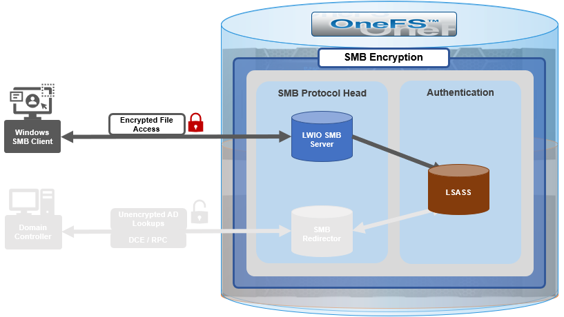
However, prior to OneFS 9.5, this did not include encrypted communications between the SMB redirector and Active Directory (AD) domain controller (DC). While Microsoft added support for SMB encryption in SMB 3.0, the redirector in OneFS 9.4 and prior releases only supported Microsoft’s earlier SMB 2.002 dialect.
When OneFS connects to Active Directory for tasks requiring remote procedure calls (RPCs), such as joining a domain, NTLM authentication, or resolving usernames and SIDs, these SMB connections are established from OneFS as the client connecting to a domain controller server.
As outlined in the Windows SMB security documentation, by default, and starting with Windows 2012 R2, domain admins can choose to encrypt access to a file share, which can include a domain controller. When encryption is enabled, only SMB3 connections are permitted.

With OneFS 9.5, the OneFS SMB redirector now supports SMB3, thereby allowing the Local Security Authority Subsystem Service (LSASS) daemon to communicate with domain controllers running Windows Server 2012 R2 and later over an encrypted session.
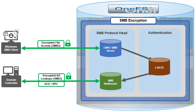
The OneFS redirector, also known as the ‘rdr driver’, is a stripped-down SMB client with minimal functionality, only supporting what is absolutely necessary.
Under the hood, OneFS SMB encryption and decryption use standard OpenSSL functions, and AES-128-CCM encryption is negotiated during SMB negotiate phase.
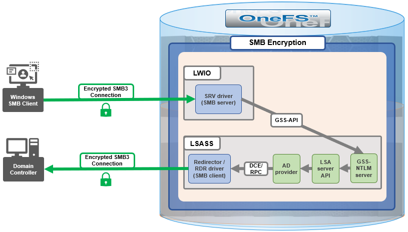
Although everything stems from the NTLM authentication requested by SMB server, the sequence of calls leads to the redirector establishing an SMB connection to the AD domain controller.
With OneFS 9.5, no configuration is required to enable SMB encryption in most situations, and there are no WebUI OR CLI configuration settings for the redirector.
With the default OneFS configuration, the redirector supports encryption if negotiated but it does not require it. Similarly, if the Active Directory domain requires encryption, the OneFS redirector will automatically enable and use encryption. However, if the OneFS redirector is explicitly configured to require encryption and the domain controller does not support encryption, the connection will fail.
The OneFS redirector encryption settings include:
Key | Values | Description |
Smb3EncryptionEnabled | Boolean. Default is ‘1’ == Enabled | Enable or disable SMB3 encryption for OneFS redirector. |
Smb3EncryptionRequired | Boolean. Default is ‘0’ == Not required. | Require or do not require the redirector connection to be encrypted. |
MaxSmb2DialectVersion | Default is ‘max’ == SMB 3.0.2 | Set the SMB dialect, so the redirector will support it. The maximum is currently SMB 3.0.2. |
The above keys and values are stored in the OneFS Likewise SMB registry and can be viewed and configured with the ‘lwreqshell’ utility. For example, to view the SMB redirector encryption config settings:
# /usr/likewise/bin/lwregshell list_values "HKEY_THIS_MACHINE\Services\lwio\Parameters\Drivers\rdr" | grep -i encrypt
"Smb3EncryptionEnabled" REG_DWORD 0x00000001 (1)
"Smb3EncryptionRequired" REG_DWORD 0x00000000 (0)
The following syntax can be used to disable the ‘Smb3EncryptionRequired’ parameter by setting it to value ‘1’:
# /usr/likewise/bin/lwregshell set_value "[HKEY_THIS_MACHINE\Services\lwio\Parameters\Drivers\rdr]" "Smb3EncryptionRequired" "0x00000001"
# /usr/likewise/bin/lwregshell list_values "HKEY_THIS_MACHINE\Services\lwio\Parameters\Drivers\rdr" | grep -i encrypt
"Smb3EncryptionEnabled" REG_DWORD 0x00000001 (1)
"Smb3EncryptionRequired" REG_DWORD 0x00000001 (1)
Similarly, to restore the ‘Smb3EncryptionRequired’ parameter’s default value of ‘0’ (ie. not required):
# /usr/likewise/bin/lwregshell set_value "[HKEY_THIS_MACHINE\Services\lwio\Parameters\Drivers\rdr]" "Smb3EncryptionEnabled" "0x00000001"
Note that, during the upgrade to OneFS 9.5, any nodes still running the old version will not be able to NTLM-authenticate if the DC they have affinity with requires encryption.
While redirector encryption is implemented in user space (in contrast to the SMB server, which is in the kernel), since it involves OpenSSL, the library does take advantage of hardware acceleration on the processor and utilizes AES-NI. As such, performance is only minimally impacted when the number of NTLM authentications to the AD domain is very large.
Also note that redirector encryption also only currently supports only AES-128-CCM encryption provided in the SMB 3.0.0 and 3.0.2 dialects. OneFS does not use AES-128-GCM encryption, available in the SMB 3.1.1 dialect (the latest), at this time.
When it comes to troubleshooting the redirector, the lwregshell tool can be used to verify its configuration settings. For example, to view the redirector encryption settings:
# /usr/likewise/bin/lwregshell list_values "HKEY_THIS_MACHINE\Services\lwio\Parameters\Drivers\rdr" | grep -i encrypt
"Smb3EncryptionEnabled" REG_DWORD 0x00000001 (1)
"Smb3EncryptionRequired" REG_DWORD 0x00000000 (0)
Similarly, to find the maximum SMB version supported by the redirector:
# /usr/likewise/bin/lwregshell list_values "HKEY_THIS_MACHINE\Services\lwio\Parameters\Drivers\rdr" | grep -i dialect
"MaxSmb2DialectVersion" REG_SZ "max"
The ‘lwsm’ CLI utility with the following syntax will confirm the status of the various lsass components:
# /usr/likewise/bin/lwsm list | grep lsass
lsass [service] running (lsass: 5164)
netlogon [service] running (lsass: 5164)
rdr [driver] running (lsass: 5164)
It can also be used to show and modify the logging level. For example:
# /usr/likewise/bin/lwsm get-log rdr
<default>: syslog LOG_CIFS at WARNING
# /usr/likewise/bin/lwsm set-log-level rdr - debug
# /usr/likewise/bin/lwsm get-log rdr
<default>: syslog LOG_CIFS at DEBUG
When finished, rdr logging can be returned to its previous log level as follows:
# /usr/likewise/bin/lwsm set-log-level rdr - warning
# /usr/likewise/bin/lwsm get-log rdr
<default>: syslog LOG_CIFS at WARNING
Additionally, the existing ‘lwio-tool’ utility has been modified in OneFS 9.5 to include functionality allowing simple test connections to domain controllers (no NTLM) via the new ‘rdr’ syntax:
# /usr/likewise/bin/lwio-tool rdr openpipe //<domain_controller>/NETLOGON
The ‘lwio-tool’ usage in OneFS 9.5 is as follows:
# /usr/likewise/bin/lwio-tool -h
Usage: lwio-tool <command> [command-args]
commands:
iotest rundown
rdr [openpipe|openfile] username@password://domain/path
srvtest transport [query|start|stop]
testfileapi [create|createnp] <path>
Author: Nick Trimbee

AI and Model Development Performance
Thu, 31 Aug 2023 20:47:58 -0000
|Read Time: 0 minutes
There has been a tremendous surge of information about artificial intelligence (AI), and generative AI (GenAI) has taken center stage as a key use case. Companies are looking to learn more about how to build architectures to successfully run AI infrastructures. In most cases, creating a GenAI solution involves fine-tuning a pretrained foundational model and deploying it as an inference service. Dell recently published a design guide – Generative AI in the Enterprise – Inferencing, that provides an outline of the overall process.
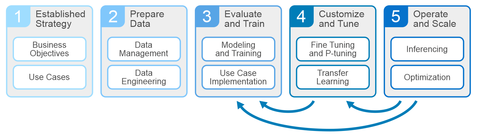
All AI projects should start with understanding the business objectives and key performance indicators. Planning, data prep, and training make up the other phases of the cycle. At the core of the development are the systems that drive these phases – servers, GPUs, storage, and networking infrastructures. Dell is well equipped to deliver everything an enterprise needs to build, develop, and maintain analytic models that serve business needs.
GPUs and accelerators have become common practice within AI infrastructures. They pull in data and training/fine-tune models within the computational capabilities of the GPU. As GPUs have evolved, their ability to handle larger models and parallel development cycles has evolved. This has left a lot of us wondering - how do we build an architecture that will support the model development that my business needs? It helps to understand a few parameters.
Defining business objectives and use cases will help shape your architecture requirements.
- The size and location of the training data set
- Model size in number of parameters and type of model being trained/fine-tuned
- Training parallelism and time to complete the training/fine-tuning.
Answering these questions helps determine how many GPUs are needed to train/fine-tune the model. Consider two main factors in GPU sizing. First is the amount of GPU memory needed to store model parameters and optimizer state. Second is the number of floating-point operations (FLOPs) needed to execute the model. Both generally scale with model size. Large models often exceed the resources of a single GPU and require spreading a single model over multiple GPUs.
Estimating the number of GPUs needed to train/fine-tune the model helps determine the server technologies to choose. When sizing servers, it’s important to balance the right GPU density and interconnect, power consumption, PCI bus technology, external port capacity, memory, and CPU. Dell PowerEdge servers include a variety of options for GPU types and density. PowerEdge XE Servers can host up to 8 NVIDIA H100 GPUs in a single server GenAI on PowerEdge XE9680, as well as the latest technologies, including NVLink, NVIDIA GPUDirect, PCIe 5.0, and NVMe disks. PowerEdge mainstream servers range from two to four GPU configurations, offering a variety of GPUs from different manufacturers. PowerEdge servers provide outstanding performance for all phases of model development. Visit Dell.com for more on PowerEdge Servers.
Now that we understand how many GPUs are needed and the servers to host them, it’s time to tackle storage. At a minimum, the storage should have capacity to host the training data set, the checkpoints during the model training, and any other data that relates to the pruning/preparing phase. The storage also needs to deliver the data at a rate the GPUs request it. The rate of delivery is multiplied by model parallelism, or the number of models being trained in parallel, and subsequently the number of GPUs requesting the data simultaneously (concurrently). Ideally, every GPU is running at 90% or better to maximize our investment, and a storage system that supports high concurrency is suited for these types of workloads.
Tools such as FIO or its cousin GDSIO (used to understand speeds and feeds of the storage system) are great for gaining hero numbers or theoretical maximums for reads/writes, but they are not representative of performance requirements for the AI development cycles. Data prep and stage shows up on the storage as random R/W, while during the training/fine-tuning phase, the GPUs are concurrently streaming reads from the storage system. Checkpoints throughout training are handled as writes back to the storage. These different points during the AI lifecycle require storage that can successfully handle these workloads at the scale determined by our model calculations and parallel development cycles.
Data scientists at Dell take great effort in understanding how different model development affects server and storage requirements. For example, language models like BERT and GPT have little effect on storage performance and resources, whereas image sequencing and DLRM models have significant or show worst case storage performance and resource demand. For this, the Dell storage teams focus testing and benchmarking on AI Deep Learning workflows based on popular image models like ResNet with real GPUs to understand the performance requirements needed to deliver data to the GPU during model training. The following image shows an architecture designed with Dell PowerEdge servers and networking with PowerScale scale-out storage.
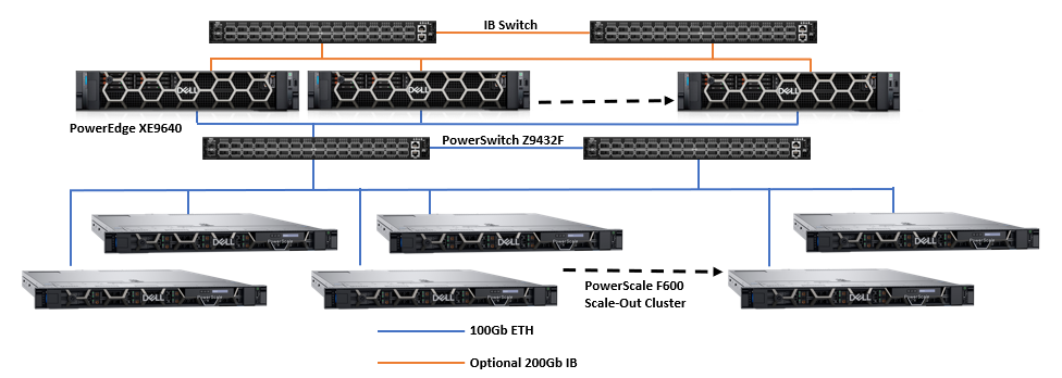
Dell PowerScale scale-out file storage is especially suited for these workloads. Each node in a PowerScale cluster delivers equivalent performance as the cluster and workloads scale. The following images show how PowerScale performance scales linearly as GPUs are increased, while the performance of each individual GPU remains constant. The scale-out architecture of PowerScale file storage easily supports AI workflows from small to large.
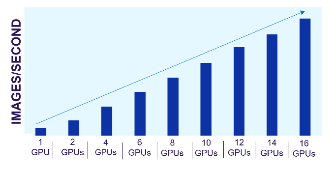
Figure 1. PowerScale linear performance
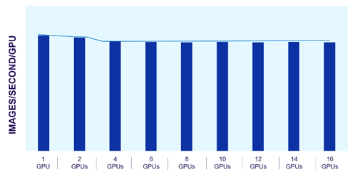
Figure 2. Consistent GPU performance with scale
The predictability of PowerScale allows us to estimate the storage resources needed for model training and fine-tuning. We can easily scale these architectures based on the model type and size along with the number and type of GPUs required.
Architecting for small and large AI workloads is challenging and takes planning. Understanding performance needs and how the components in the architecture will perform as the AI workload demand scales is critical.
Author: Darren Miller

Dell PowerScale and Marvel Partner to Create Optimal Media Workflows
Tue, 01 Aug 2023 17:03:47 -0000
|Read Time: 0 minutes
Now in its 9th generation, Emmy-award-winning Dell PowerScale storage has been field proven in media workflows for over two decades and is the world’s most flexible1, efficient2, and secure3 scale-out NAS solution.
Our partnership with Marvel Studios is a wonderful example of the innovations we collaborate on with leading media and entertainment companies around the world—with PowerScale as the preeminent storage solution that enables data-driven workflows to accelerate content-creation pipelines.
Hear about Marvel Studios’ implementation of PowerScale directly in this educational video series from The Advanced Imaging Society:
The PowerScale OneFS advantage
The underlying OneFS file system leverages the foundations of clustered high-performance computing to solve the challenges of data protection at scale and client accessibility in a massively parallelized way. In practice, a single namespace that easily scales out with nodes to increase performance and capacity is a fundamentally game-changing architecture.
Media workflows require increased levels of access for the applications and users to provide for workflow collaboration in balance with security that doesn’t impede performance. Further, performance and access can’t be impeded even during hardware failures such as drive rebuilds or system upgrades to ensure that production work can continue uninterrupted while maintenance is being performed in the background.
Maximizing uptime correlates with fundamental business needs including meeting project timelines and budgets while ensuring that personnel have access to the content at the required performance levels, even during a background maintenance activity.
As a sufficiently advanced enterprise-class solution, PowerScale incorporates these capabilities to eliminate complexity and provide for increased uptime through its self-healing and self-managing functionality. (For more information, see the PowerScale OneFS Technical Overview.) This takes many of the traditional storage management burdens off the administrator’s plate, lowering the overhead and time needed to maintain storage, which is often increasing in size and scale.
While the benefits of collaboration over Ethernet-based storage are inherent in PowerScale, the user experience is also paramount in correlation with the performance of the network and underlying storage system. Operations such as playout and scrubbing need to perform reliably with no frame drops while providing response times that look and feel equivalent to working from the local workstation.
As I’ve participated in the development of media storage solutions from SCSI, Fibre Channel, iSCSI, SAN, and Ethernet, I’ve been able to test and compare solutions over the years and have closely watched the evolution and trends of these protocols in relation to their ability to support media workflows.
In 2007, I demonstrated real-time color grading with uncompressed content over 1 Gb Ethernet, the first of its kind. At the time, using Ethernet-based storage for color grading was largely unheard of, with few applications supporting it. That was more of an exercise to showcase the art of the possible in comparison with Fibre Channel-based solutions. The wider adoption of Ethernet for this particular use case was not yet of high interest because Ethernet speeds still needed to evolve. However, 1 Gb Ethernet was very appropriate for compressed media workflows and rendering, which were well aligned with the high-performance, scale-out design of PowerScale.
As 10 Gb Ethernet speeds became prevalent, there was a significant uptick in the adoption of Ethernet-based storage compared to Fibre Channel-based solutions for media use cases. I also started to see more datasets being moved over Ethernet rather than by sneaker net, physically delivering drives and tapes between locations. This led to cost and time savings for project timelines and budgets, among other benefits.
Fast-forward to 2014, when, with the OneFS 7.1.1 version supporting SMB multi-channel, we were able to use two 10 Gb Ethernet connections to support a stream of full resolution uncompressed 4K, whereas a single 10 Gb connection was only capable of supporting 2K full resolution streams. This began an adoption trend of Ethernet solutions for 4K full-resolution workflows.
In 2017, with the release of the F800 All-Flash PowerScale and OneFS 8.1, 40 Gb Ethernet speeds were supported. The floodgates were unlocked for media workflows. Multiple full-resolution 2K and 4K workflows could run on a single shared OneFS namespace with uncompromised performance. Workload consolidation could be performed and started to eliminate the need for multiple discreet storage solutions that were each supporting different parts of the pipeline, bringing all those together under a single unified OneFS namespace to streamline environments.
Complete pipeline transformations were taking place and began to replace iSCSI and Fibre Channel-based solutions at an accelerated pace, as those solutions were siloed within workgroups and inflexible with the emerging needs of collaboration. When the PowerScale F900 NVMe solution supporting 100 Gb Ethernet came out in 2021, the technology was set to change the industry yet again.
With the increasing prevalence of 100 Gb Ethernet over these past few years, performance parity with Fibre Channel-based solutions to support full-resolution 4K, 8K, and all related media workflows in between is no longer in question. Native Ethernet-based solutions are preferred for many reasons—including cloud capability, scale, cost, and supportability—to facilitate unstructured media datasets, leveraging the abundance of network engineering talent in comparison to Fibre Channel-trained engineers.
With reliability, performance, and shared access for collaboration delivering uncompromised benefits, we now look to several PowerScale storage capabilities that enable rich media ecosystems to be further streamlined and flourish.
There are four additional key areas of focus and their underlying feature sets that are increasingly important to today’s media ecosystems. They encompass:
- Security, physical and logical
- API orchestration
- Data movement
- Quality of service
Security
- In relation to PowerScale being the world’s most secure scale-out NAS solution and in alignment with the Trusted Partner Network (TPN), the OneFS operating system meets or exceeds the Motion Picture Association (MPA) Content Security Best Practices (CSBP) in all relevant areas of the Content Security Model (CSM).4
- Further, I’m seeing greater adoption of self-encrypting drives (SEDs), which provide encryption at the physical layer. Security auditing and multi-factor authentication are among the features being employed to protect the logical layer. Specifically, auditing has been available and used for many years now to provide a range of benefits beyond security.
- The real-time audit logs can be parsed to provide performance introspection, analysis, and user-trend insights in addition to identifying abnormal data-access patterns. The logs can also be used to correlate with levels of access to specific projects and files, correlating back to business-level insights and reports as well.
- I’m also keen on mentioning the OneFS embedded firewall, which provides connection-level protection at the storage network layer. Firewalls are typically employed in front of the storage or further upstream on the network, so having an additional firewall within the storage that protects the network ports on the storage itself is a powerful layer of security.
For more information about OneFS security, see Dell PowerScale OneFS: Security Considerations.
Data orchestration
- Data orchestration is paramount to workflow automation. If aspects of workflows can be automated and don’t require an operator to make a decision, they should be automated to remove the possibility for operator error and streamline the environment to accelerate workflows where possible.
- Orchestration is enabled through API calls to integrate PowerScale with the environment’s application layers, which can take mundane repeatable tasks off the operator’s plate and increase workflow efficiency.
For more information about PowerScale data orchestration, see the OneFS documentation on Dell Support.
Data movement
- Data movement is integral to media workflows today, and for that we look to the high-performance, highly reliable SyncIQ protocol embedded in PowerScale OneFS. SyncIQ facilitates secure, parallelized transfer of datasets between PowerScale solutions, providing strong benefits for media workflows. Replication policies can be set up or initiated ad hoc to transfer datasets between PowerScale solutions over the network.
- With SyncIQ, PowerScale is both a storage platform and a data transfer engine, so additional servers and transfer applications, which would incur additional cost and management overhead, don’t need to be implemented in front of PowerScale.
The PowerScale Backup and Recovery Guide provides more information about data movement capabilities in OneFS.
Quality of service
- Quality of service is increasingly important and has always been of interest for media workflows. SmartQoS is an embedded OneFS feature that monitors front-end protocol traffic over NFS, SMB, and S3. It allows limits to be set for the number of protocol operations to tie them back to performance SLAs, prioritization of workloads, and support for throttling to prevent specific clients from saturating a connection. I’ve seen an unthrottled copy job use the available connection bandwidth and interrupt a playout, so that’s an example of a use case where SmartQoS can be applied.
- Clients can be logically grouped and monitored with all kinds of metrics being captured to quantify and profile workloads. Introspection into read and write latencies, IOPS, and many other metrics on a per-protocol, path, IP address, user, and group basis can be captured and correlated in real time. Metrics can be tracked and enforced to provide quality of service for specific classes of users and workflows, which can all be defined to manage workloads.
For more information about quality of service in OneFS, see this blog post: OneFS SmartQoS.
Summary
The capabilities of PowerScale storage with OneFS are delivering unparalleled scale and feature benefits that elevate the capabilities of media entertainment use cases from the highest performance workflows to highly dense archives. Standardization on this enterprise-class, secure, and collaborative platform is the key to unlocking innovation and advancing your media pipelines.
1 Based on internal analysis of publicly available information sources, February 2023. CLM-0013892.
2 Based on Dell analysis comparing efficiency-related features: data reduction, storage capacity, data protection, hardware, space, lifecycle management efficiency, and ENERGY STAR certified configurations, June 2023. CLM-008608.
3 Based on Dell analysis comparing cyber-security software capabilities offered for Dell PowerScale vs. competitive products, September 2022.
4 Dell Technologies Executive Summary of Compliance with Media Industry Security Guidelines, https://www.delltechnologies.com/asset/en-ae/products/storage/briefs-summaries/tpn-executive-summary-compliance-statement.pdf.
Author: Brian Cipponeri, Global Solutions Architect
Dell Technologies – Unstructured Data Solutions

Diary of a VFX Systems Engineer—Part 1: isi Statistics
Thu, 17 Aug 2023 20:57:36 -0000
|Read Time: 0 minutes
Welcome to the first in a series of blog posts to reveal some helpful tips and tricks when supporting media production workflows on PowerScale OneFS.
OneFS has an incredible user-drivable toolset underneath the hood that can grant you access to data so valuable to your workflow that you'll wonder how you ever lived without it.
When working on productions in the past I’ve witnessed and had to troubleshoot many issues that arise in different parts of the pipeline. Often these are in the render part of the pipeline, which is what I’m going to focus on in this blog.
Render pipelines are normally fairly straightforward in their make-up, but they require everything to be just right to ensure that you don’t starve a cluster of resource, which, if your cluster is at the center of all of your production operations can cause a whole studio outage, causing impact to your creatives, revenue loss, and unnecessary delays in production.
Did you know that any command that is run on a OneFS cluster is an API call down to the OneFS API. This can be observed if you add the --debug flag to any command that you run on the CLI. As shown here, this displays the call information that was sent to gather the information requested, which is helpful if you're integrating your own administration tools into your pipeline.
# isi --debug statistics client list
        2023-06-22 10:24:41,086 DEBUG rest.py:80: >>>GET ['3', 'statistics', 'summary', 'client']
        2023-06-22 10:24:41,086 DEBUG rest.py:81:    args={'sort': 'operation_rate,in,out,time_avg,node,protocol,class,user.name,local_name,remote_name', 'degraded': 'False', 'timeout': '15'}
        body={}
        2023-06-22 10:24:41,212 DEBUG rest.py:106: <<<(200, {'content-type': 'application/json', 'allow': 'GET, HEAD', 'status': '200 Ok'}, b'n{\n"client" : [  ]\n}\n')
There are so many potential applications for OneFS API calls, from monitoring statistics on the cluster to using your own tools for creating shares, and so on. (We'll go deeper into the API in a future post!)
When we are facing production-stopping activities on a cluster, they're often caused by a rogue process outside the OneFS environment that is as yet unknown to us, which means we have to figure out what that process is and what it is doing.
In walks isi statistics.
By using the isi statistics command, we can very quickly see what is happening on a cluster at any given time. It can give us live reports on which user or connection is causing an issue, how much I/O they're generating as well as what their IP is, what protocol they’re connected using, and so on.
If the cluster is experiencing a sudden slowdown (during a render, for example), we can run a couple of simple statistics commands to show us what the cluster is doing and who's hitting it the hardest. Some examples of these commands are as follows:
isi statistics system --n=all --format=top
Displays all nodes’ real-time statistics in a *NIX “top” style format:
# isi statistics system --n=all --format=top
Node   CPU SMB FTP HTTP NFS HDFS  S3 Total NetIn NetOut DiskIn DiskOut
 All 33.7% 0.0 0.0  0.0 0.0   0.0 0.0   0.0 401.6  215.6     0.0     0.0
   1 33.7% 0.0 0.0  0.0 0.0   0.0 0.0   0.0 401.6  215.6     0.0     0.0
isi statistics client list --totalby=UserName --sort=Ops
This command displays all clients connected and shows their stats, including the UserName they are connected with. It places the users with the highest number of total Ops at the top so that you can track down the user or account that is hitting the storage the hardest.
# isi statistics client --totalby=UserName --sort=Ops
 Ops     In  Out  TimeAvg   Node  Proto  Class   UserName  LocalName  RemoteName
-----------------------------------------------------------------------------
12.8 12.6M 1.1k  95495.8     *       *      *      root          *           *
-----------------------------------------------------------------------------
isi statistics client --UserName=<username> --sort=Ops
This command goes a bit further and breaks down ALL of the Ops by type being requested by that user. If you know the protocol that the user you’re investigating is using we can also add the operator “--proto=<nfs/smb>” to the command too.
# isi statistics client --user-names=root --sort=Ops
 Ops     In   Out  TimeAvg   Node  Proto           Class  UserName        LocalName    RemoteName
----------------------------------------------------------------------------------------------
 5.8   6.1M 487.2 142450.6     1   smb2           write      root 192.168.134.101 192.168.134.1
 2.8 259.2 332.8    497.2      1   smb2      file_state      root 192.168.134.101 192.168.134.1
 2.6 985.6 549.8  10255.1      1   smb2          create      root 192.168.134.101 192.168.134.1
 2.6 275.0 570.6   3357.5      1   smb2  namespace_read      root 192.168.134.101 192.168.134.1
 0.4   85.6  28.0   3911.5      1   smb2 namespace_write      root 192.168.134.101 192.168.134.1
----------------------------------------------------------------------------------------------
The other useful command, particularly when troubleshooting ad hoc performance issues, is isi statistics heat.
isi statistics heat list --totalby=path --sort=Ops | head -12
This command shows the top 10 file paths that are being hit by the largest number of I/O operations.
# isi statistics heat list --totalby=path --sort=Ops | head -12
  Ops   Node  Event  Class Path
----------------------------------------------------------------------------------------------------
141.7     *       *      * /ifs/
127.8     *       *      * /ifs/.ifsvar
 86.3      *      *      * /ifs/.ifsvar/modules
 81.7      *      *      * SYSTEM (0x0)
 33.3      *      *      * /ifs/.ifsvar/modules/tardis
 28.6      *      *      * /ifs/.ifsvar/modules/tardis/gconfig
 28.3      *      *      * /ifs/.ifsvar/upgrade
 13.1      *      *      * /ifs/.ifsvar/upgrade/logs/UpgradeLog-1.db
 11.9      *      *      * /ifs/.ifsvar/modules/tardis/namespaces/healthcheck_schedules.sqlite
 10.5      *      *      * /ifs/.ifsvar/modules/cloud
Once you have all this information, you can now find the user or process (based on IP, UserName, and so on) and figure out what that user is doing and what's causing the render to fail or high I/O generation. In many situations, it will be an asset that is either sitting on a lower-performance tier of the cluster or, if you're using a front side render cache, an asset that is sitting outside of the pre-cached path, so the spindles in the cluster are taking the I/O hit.
For more tips and tricks that can help to save you valuable time, keep checking back. In the meantime, if you have any questions, please feel free to get in touch and I'll do my best to help!
Author: Andy Copeland
Media & Entertainment Solutions Architect

OneFS Key Manager Rekey Support
Mon, 24 Jul 2023 19:16:34 -0000
|Read Time: 0 minutes
The OneFS key manager is a backend service that orchestrates the storage of sensitive information for PowerScale clusters. To satisfy Dell’s Secure Infrastructure Ready requirements and other public and private sector security mandates, the manager provides the ability to replace, or rekey, cryptographic keys.
The quintessential consumer of OneFS key management is data-at-rest encryption (DARE). Protecting sensitive data stored on the cluster with cryptography ensures that it’s guarded against theft, in the event that drives or nodes are removed from a PowerScale cluster. DARE is a requirement for federal and industry regulations, ensuring data is encrypted when it is stored. OneFS has provided DARE solutions for many years through secure encrypted drives (SEDs) and the OneFS key management system.
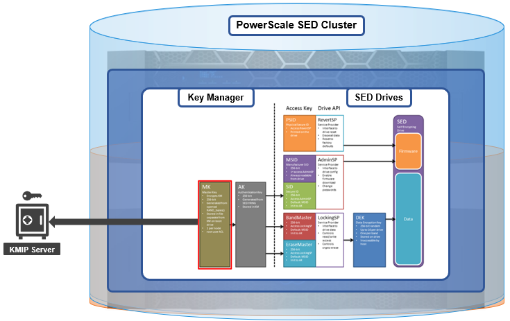
A 256-bit key (MK) encrypts the Key Manager Database (KMDB) for SED and cluster domains. In OneFS 9.2 and later, the MK for SEDs can either be stored off-cluster on a KMIP server or locally on a node (the legacy behavior).
However, there are a variety of other consumers of the OneFS key manager, in addition to DARE. These include services and protocols such as:
| Service | Description |
|---|---|
CELOG | Cluster event log |
CloudPools | Cluster tier to cloud service |
Electronic mail | |
FTP | File transfer protocol |
IPMI | Intelligent platform management interface for remote cluster console access |
JWT | JSON web tokens |
NDMP | Network data management protocol for cluster backups and DR |
Pstore | Active directory and Kerberos password store |
S3 | S3 object protocol |
SyncIQ | Cluster replication service |
SmartSync | OneFS push and pull replication cluster and cloud replication service |
SNMP | Simple network monitoring protocol |
SRS | Old Dell support remote cluster connectivity |
SSO | Single sign-on |
SupportAssist | Remote cluster connectivity to Dell Support |
OneFS 9.5 introduces a number of enhancements to the venerable key manager, including:
- The ability to rekey keystores. Rekey operation will generate a new MK and re-encrypt all entries stored with the new key.
- New CLI commands and WebUI options to perform a rekey operation or schedule key rotation on a time interval.
- New commands to monitor the progress and status of a rekey operation.
As such, OneFS 9.5 now provides the ability to rekey the MK, irrespective of where it is stored.
Note that when you are upgrading from an earlier OneFS release, the new rekey functionality is only available once the OneFS 9.5 upgrade has been committed.
Under the hood, each provider store in the key manager consists of secure backend storage and an MK. Entries are kept in a SQLite database or key-value store. A provider datastore uses its MK to encrypt all its entries within the store.
During the rekey process, the old MK is only deleted after a successful re-encryption with the new MK. If for any reason the process fails, the old MK is available and remains as the current MK. The rekey daemon retries the rekey every 15 minutes if the process fails.
The OneFS rekey process is as follows:

- A new MK is generated, and internal configuration is updated.
- Any entries in the provider store are decrypted and encrypted with the new MK.
- If the prior steps are successful, the previous MK is deleted.
To support the rekey process, the MK in OneFS 9.5 now has an ID associated with it. All entries have a new field referencing the MK ID.
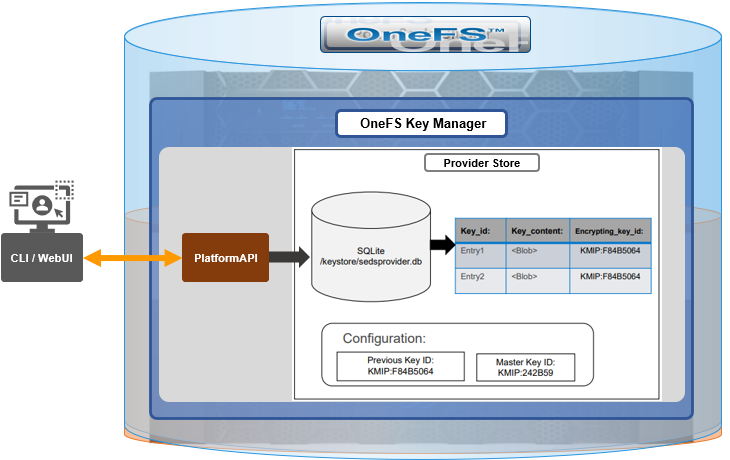
During the rekey operation, there are two MK values with different IDs, and all entries in the database will associate which key they are encrypted by.
In OneFS 9.5, the rekey configuration and management is split between the cluster keys and the SED keys:
| Rekey component | Detail |
|---|---|
SED |
|
Cluster |
|
SED keys rekey

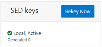
The SED key manager rekey operation can be managed through a DARE cluster’s CLI or WebUI, and it can either be automatically scheduled or run manually on demand. The following CLI syntax can be used to manually initiate a rekey:
# isi keymanager sed rekey start
Alternatively, to schedule a rekey operation, for example, to schedule a key rotation every two months:
# isi keymanager sed rekey modify --key-rotation=2m
The key manager status for SEDs can be viewed as follows:
# isi keymanager sed status
 Node Status  Location   Remote Key ID  Key Creation Date   Error Info(if any)
-----------------------------------------------------------------------------
1   LOCAL   Local                    1970-01-01T00:00:00
-----------------------------------------------------------------------------
Total: 1
Alternatively, from the WebUI, go to Access > Key Management > SED/Cluster Rekey, select Automatic rekey for SED keys, and configure the rekey frequency:
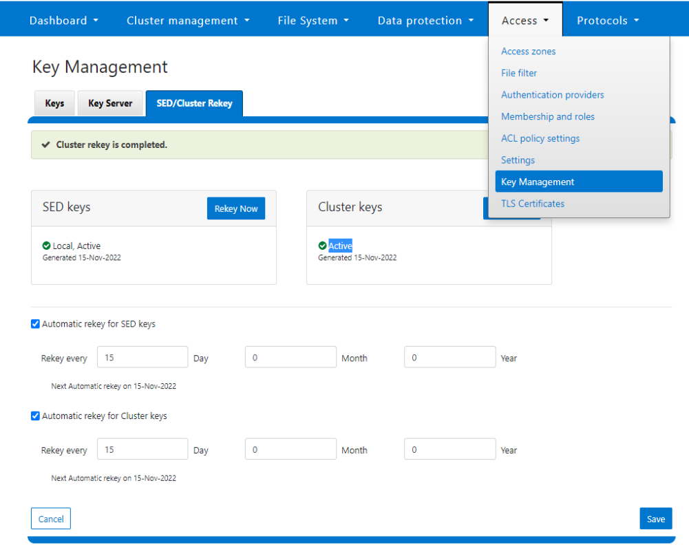
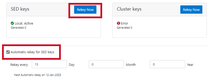
Note that for SED rekey operations, if a migration from local cluster key management to a KMIP server is in progress, the rekey process will begin once the migration is complete.
Cluster keys rekey

As mentioned previously, OneFS 9.5 also supports the rekey of cluster keystore domains. This cluster rekey operation is available through the CLI and the WebUI and may either be scheduled or run on demand. The available cluster domains can be queried by running the following CLI syntax:
# isi keymanager cluster status
Domain     Status  Key Creation Date   Error Info(if any)
----------------------------------------------------------
CELOG      ACTIVE  2023-04-06T09:19:16
CERTSTORE  ACTIVE  2023-04-06T09:19:16
CLOUDPOOLS ACTIVE   2023-04-06T09:19:16
EMAIL      ACTIVE  2023-04-06T09:19:16
FTP        ACTIVE  2023-04-06T09:19:16
IPMI_MGMT  IN_PROGRESS  2023-04-06T09:19:16
JWT        ACTIVE  2023-04-06T09:19:16
LHOTSE     ACTIVE  2023-04-06T09:19:11
NDMP       ACTIVE  2023-04-06T09:19:16
NETWORK    ACTIVE  2023-04-06T09:19:16
PSTORE     ACTIVE  2023-04-06T09:19:16
RICE       ACTIVE  2023-04-06T09:19:16
S3         ACTIVE  2023-04-06T09:19:16
SIQ        ACTIVE  2023-04-06T09:19:16
SNMP       ACTIVE  2023-04-06T09:19:16
SRS        ACTIVE  2023-04-06T09:19:16
SSO        ACTIVE  2023-04-06T09:19:16
----------------------------------------------------------
Total: 17
The rekey process generates a new key and re-encrypts the entries for the domain. The old key is then deleted.
Performance-wise, the rekey process does consume cluster resources (CPU and disk) as a result of the re-encryption phase, which is fairly write-intensive. As such, a good practice is to perform rekey operations outside of core business hours or during scheduled cluster maintenance windows.
During the rekey process, the old MK is only deleted once a successful re-encryption with the new MK has been confirmed. In the event of a rekey process failure, the old MK is available and remains as the current MK.
A rekey may be requested immediately or may be scheduled with a cadence. The rekey operation is available through the CLI and the WebUI. In the WebUI, go to Access > Key Management > SED/Cluster Rekey.
To start a rekey of the cluster domains immediately, from the CLI run the following syntax:
# isi keymanager cluster rekey start
Are you sure you want to rekey the master passphrase? (yes/[no]):yes
Alternatively, from the WebUI, go to Access under the SED/Cluster Rekey tab, and click Rekey Now next to Cluster keys:
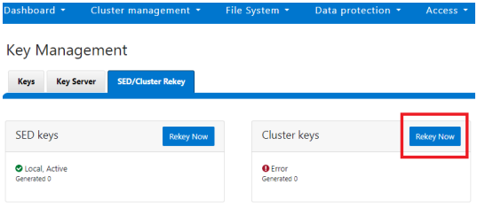
A scheduled rekey of the cluster keys (excluding the SED keys) can be configured from the CLI with the following syntax:
# isi keymanager cluster rekey modify –-key-rotation [YMWDhms]
Specify the frequency of the Key Rotation field as an integer, using Y for years, M for months, W for weeks, D for days, h for hours, m for minutes, and s for seconds. For example, the following command will schedule the cluster rekey operation to run every six weeks:
# isi keymanager cluster rekey view
 Rekey Time: 1970-01-01T00:00:00
 Key Rotation: Never
 # isi keymanager cluster rekey modify --key-rotation 6W
 # isi keymanager cluster rekey view
 Rekey Time: 2023-04-28T18:38:45
 Key Rotation: 6W
The rekey configuration can be easily reverted back to on demand from a schedule as follows:
# isi keymanager cluster rekey modify --key-rotation Never
 # isi keymanager cluster rekey view
 Rekey Time: 2023-04-28T18:38:45
 Key Rotation: Never
Alternatively, from the WebUI, under the SED/Cluster Rekey tab, select the Automatic rekey for Cluster keys checkbox and specify the rekey frequency. For example:
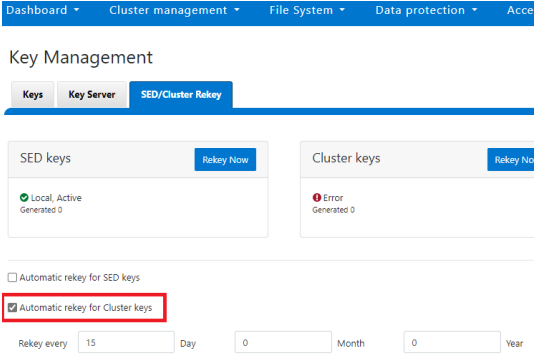
In an event of a rekeying failure, a CELOG KeyManagerRekeyFailed or KeyManagerSedsRekeyFailed event is created. Since SED rekey is a node-local operation, the KeyManagerSedsRekeyFailed event information will also include which node experienced the failure.
Additionally, current cluster rekey status can also be queried with the following CLI command:
# isi keymanager cluster status
Domain     Status  Key Creation Date   Error Info(if any)
----------------------------------------------------------
CELOG      ACTIVE  2023-04-06T09:19:16
CERTSTORE  ACTIVE  2023-04-06T09:19:16
CLOUDPOOLS ACTIVE   2023-04-06T09:19:16
EMAIL      ACTIVE  2023-04-06T09:19:16
FTP        ACTIVE  2023-04-06T09:19:16
IPMI_MGMT  ACTIVE  2023-04-06T09:19:16
JWT        ACTIVE  2023-04-06T09:19:16
LHOTSE     ACTIVE  2023-04-06T09:19:11
NDMP       ACTIVE  2023-04-06T09:19:16
NETWORK    ACTIVE  2023-04-06T09:19:16
PSTORE     ACTIVE  2023-04-06T09:19:16
RICE       ACTIVE  2023-04-06T09:19:16
S3         ACTIVE  2023-04-06T09:19:16
SIQ        ACTIVE  2023-04-06T09:19:16
SNMP       ACTIVE  2023-04-06T09:19:16
SRS        ACTIVE  2023-04-06T09:19:16
SSO        ACTIVE  2023-04-06T09:19:16
----------------------------------------------------------
Total: 17
Or, for SEDs rekey status:
# isi keymanager sed status
 Node Status  Location   Remote Key ID  Key Creation Date   Error Info(if any)
-----------------------------------------------------------------------------
1   LOCAL   Local                    1970-01-01T00:00:00
2   LOCAL   Local                    1970-01-01T00:00:00
3   LOCAL   Local                    1970-01-01T00:00:00
4   LOCAL   Local                    1970-01-01T00:00:00
-----------------------------------------------------------------------------
Total: 4
The rekey process also outputs to the /var/log/isi_km_d.log file, which is a useful source for additional troubleshooting.
If an error in rekey occurs, the previous MK is not deleted, so entries in the provider store can still be created and read as normal. The key manager daemon will retry the rekey operation in the background every 15 minutes until it succeeds.
Author: Nick Trimbee

OneFS Password Security Policy
Mon, 24 Jul 2023 20:08:49 -0000
|Read Time: 0 minutes
Among the slew of security enhancements introduced in OneFS 9.5 is the ability to mandate a more stringent password policy. This is required to comply with security requirements such as the U.S. military STIG, which stipulates:
| Requirement | Description |
|---|---|
Length | An OS or network device must enforce a minimum 15-character password length. |
Percentage | An OS must require the change of at least 50% of the total number of characters when passwords are changed. |
Position | A network device must require that when a password is changed, the characters are changed in at least eight of the positions within the password. |
Temporary password | The OS must allow the use of a temporary password for system logons with an immediate change to a permanent password. |
The OneFS password security architecture can be summarized as follows:
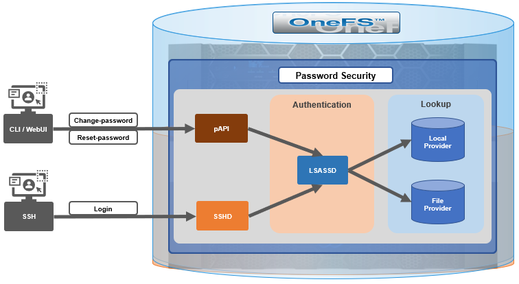
Within the OneFS security subsystem, authentication is handled in OneFS by LSASSD, the daemon used to service authentication requests for lwiod.
| Component | Description |
|---|---|
LSASSD | The local security authority subsystem service (LSASS) handles authentication and identity management as users connect to the cluster. |
File provider | The file provider includes users from /etc/password and groups from /etc/groups. |
Local provider | The local provider includes local cluster accounts such as anonymous, guest, and so on. |
SSHD | The OpenSSH Daemon provides secure encrypted communications between a client and a cluster node over an insecure network. |
pAPI | The OneFS Platform API provides programmatic interfaces to OneFS configuration and management through a RESTful HTTPS service. |
In OneFS AIMA, there are several different kinds of backend providers: Local provider, file provider, AD provider, NIS provider, and so on. Each provider is responsible for the management of users and groups inside the provider. For OneFS password policy enforcement, the local and file providers are the focus.
The local provider is based on an SamDB style file stored with prefix path of /ifs/.ifsvar, and its provider settings can be viewed by the following CLI syntax:
# isi auth local view System
On the other hand, the file provider is based on the FreeBSD spwd.db file, and its configuration can be viewed by the following CLI command:
# isi auth file view System
Each provider stores and manage its own users. For the local provider, isi auth users create CLI command will create a user inside the provider by default. However, for the file provider, there is no corresponding command. Instead, the OneFS pw CLI command can be used to create a new file provider user.
After the user is created, the isi auth users modify <USER> CLI command can be used to change the attributes of the user for both the file and local providers. However, not all attributes are supported for both providers. For example, the file provider does not support password expiry.
The fundamental password policy CLI changes introduced in OneFS 9.5 are as follows:
| Operation | OneFS 9.5 change | Details |
|---|---|---|
change-password | Modified | Needed to provide old password for changing so that we can calculate how many chars/percent changed |
reset-password | Added | Generates a temp password that meets current password policy for user to log in |
set-password | Deprecated | Doesn't need to provide old password |
A user’s password can now be set, changed, and reset by either root or admin. This is supported by the new isi auth users change-password or isi auth users reset-password CLI command syntax. The latter, for example, returns a temporary password and requires the user to change it on next login. After logging in with the temporary (albeit secure) password, OneFS immediately forces the user to change it:
# whoami
admin
# isi auth users reset-password user1
4$_x\d\Q6V9E:sH
# ssh user1@localhost
(user1@localhost) Password:
(user1@localhost) Your password has expired.
You are required to immediately change your password.
Changing password for user1
New password:
(user1@localhost) Re-enter password:
Last login: Wed May 17 08:02:47 from 127.0.0.1
PowerScale OneFS 9.5.0.0
# whoami
user1
Also in OneFS 9.5 and later, the CLI isi auth local view system command sees the addition of four new fields:
- Password Chars Changed
- Password Percent Changed
- Password Hash Type
- Max Inactivity Days
For example:
# isi auth local view system
                    Name: System
                  Status: active
          Authentication: Yes
    Create Home Directory: Yes
 Home Directory Template: /ifs/home/%U
        Lockout Duration: Now
       Lockout Threshold: 0
          Lockout Window: Now
             Login Shell: /bin/zsh
            Machine Name:
        Min Password Age: Now
        Max Password Age: 4W
      Min Password Length: 0
     Password Prompt Time: 2W
      Password Complexity: -
 Password History Length: 0
   Password Chars Changed: 0
Password Percent Changed: 0
      Password Hash Type: NTHash
      Max Inactivity Days: 0
The following CLI command syntax configures OneFS to require a minimum password length of 15 characters, a 50% or greater change, and 8 or more characters to be altered for a successful password reset:
# isi auth local modify system --min-password-length 15 --password-chars-changed 8 --password-percent-changed 50
Next, a command is issued to create a new user, user2, with a 10-character password:
# isi auth users create user2 --password 0123456789
Failed to add user user1: The specified password does not meet the configured password complexity or history requirements
This attempt fails because the password does not meet the configured password criteria (15 chars, 50% change, 8 chars to be altered).
Instead, the password for the new account, user2, is set to an appropriate value: 0123456789abcdef. Also, the --prompt-password-change flag is used to force the user to change their password on next login.
# isi auth users create user2 --password 0123456789abcdef –prompt-password-change 1
When the user logs in to the user2 account, OneFS immediately prompts for a new password. In the following example, a non-compliant password (012345678zyxw) is entered.
0123456789abcdef -> 012345678zyxw = Failure
This returns an unsuccessful change attempt failure because it does not meet the 15-character minimum:
# su user2
New password:
Re-enter password:
The specified password does not meet the configured password complexity requirements.
Your password must meet the following requirements:
  * Must contain at least 15 characters.
  * Must change at least 8 characters.
  * Must change at least 50% of characters.
New password:
Instead, a compliant password and successful change could be:
0123456789abcdef -> 0123456zyxwvuts = Success
The following command can also be used to change the password for a user. For example, to update user2’s password:
# isi auth users change-password user2
Current password (hit enter if none):
New password:
Confirm new password:
If a non-compliant password is entered, the following error is returned:
Password change failed: The specified password does not meet the configured password complexity or history requirements
When employed, OneFS hardening automatically enforces security-based configurations. The hardening engine is profile-based, and its STIG security profile is predicated on security mandates specified in the U.S. Department of Defense (DoD) Security Requirements Guides (SRGs) and Security Technical Implementation Guides (STIGs).
On applying the STIG hardening security profile to a cluster (isi hardening apply --profile=STIG), the password policy settings are automatically reconfigured to the following values:
| Field | Normal value | STIG hardened |
|---|---|---|
Lockout Duration | Now | Now |
Lockout Threshold | 0 | 3 |
Lockout Window | Now | 15m |
Min Password Age | Now | 1D |
Max Password Age | 4W | 8W4D |
Min Password Length | 0 | 15 |
Password Prompt Time | 2W | 2W |
Password Complexity | - | lowercase, numeric, repeat, symbol, uppercase |
Password History Length | 0 | 5 |
Password Chars Changed | 0 | 8 |
Password Percent Changed | 0 | 50 |
Password Hash Type | NTHash | SHA512 |
Max Inactivity Days | 0 | 35 |
For example:
# uname -or
Isilon OneFS 9.5.0.0

# isi hardening list
Name  Description                       Status
---------------------------------------------------
STIG  Enable all STIG security settings Applied
---------------------------------------------------
Total: 1

# isi auth local view system
                    Name: System
                  Status: active
          Authentication: Yes
   Create Home Directory: Yes
 Home Directory Template: /ifs/home/%U
        Lockout Duration: Now
       Lockout Threshold: 3
          Lockout Window: 15m
             Login Shell: /bin/zsh
             Machine Name:
        Min Password Age: 1D
        Max Password Age: 8W4D
     Min Password Length: 15
    Password Prompt Time: 2W
     Password Complexity: lowercase, numeric, repeat, symbol, uppercase
 Password History Length: 5
  Password Chars Changed: 8
Password Percent Changed: 50
      Password Hash Type: SHA512
     Max Inactivity Days: 35
Note that Password Hash Type is changed from the default NTHash to the more secure SHA512 encoding, in addition to setting the various password criteria.
The OneFS 9.5 WebUI also sees several additions and alterations to the Password policy page. These include:
| Operation | OneFS 9.5 change | Details |
|---|---|---|
Policy page | Added | New Password policy page under Access > Membership and roles |
reset-password | Added | Generates a random password that meets current password policy for user to log in |
The most obvious change is the transfer of the policy configuration elements from the local provider page to a new dedicated Password policy page.
Here’s the OneFS 9.4 View a local provider page, under Access > Authentication providers > Local providers > System:
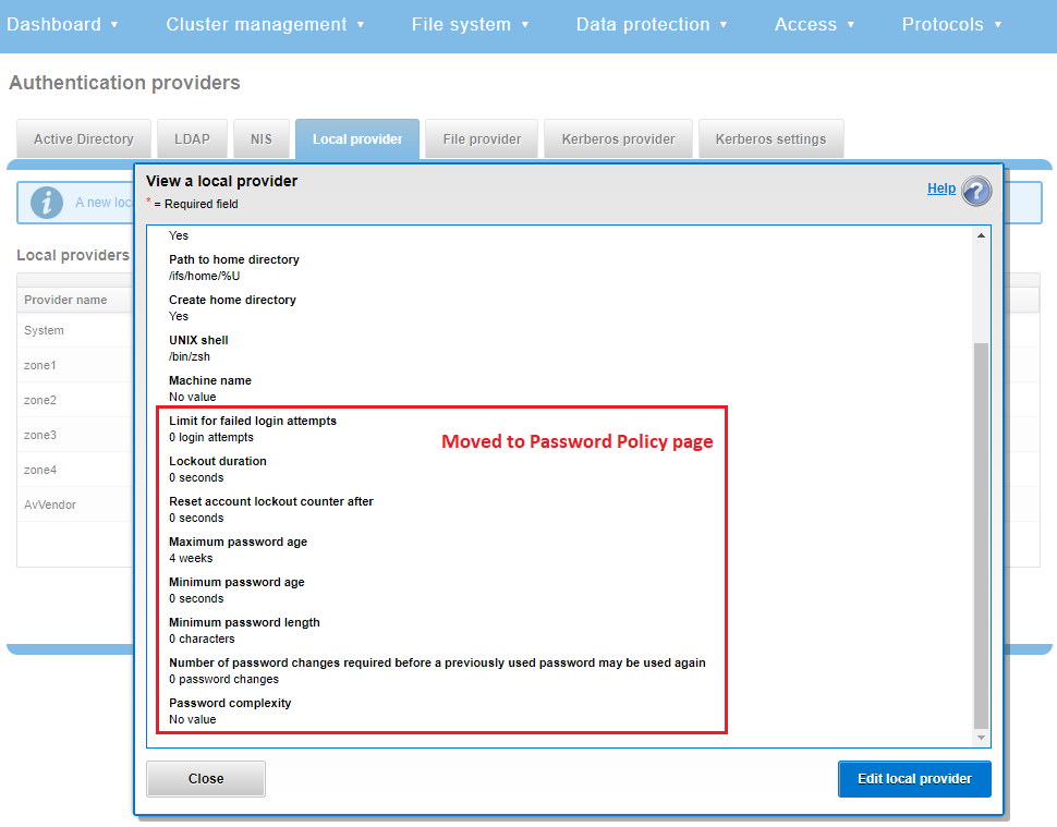
This is replaced and augmented in the OneFS 9.5 WebUI with the following page, located under Access > Membership and roles > Password policy:
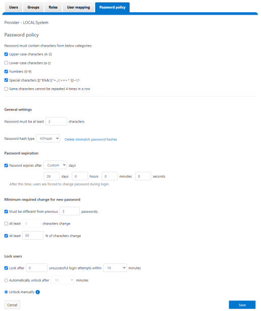
New password policy configuration options are included to require uppercase, lowercase, numeric, or special characters and limit the number of contiguous repeats of a character, and so on.
When it comes to changing a password, only a permitted user can make their change. This can be performed from a couple of locations in the WebUI. First, the user options on the task bar at the top of each screen now provides a Change password option:
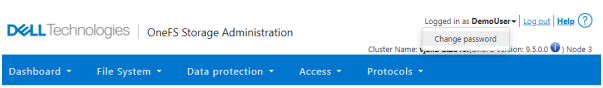
A pop-up warning message will also be displayed by the WebUI, informing the user when password expiration is imminent. This warning provides a Change Password link:
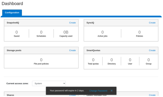
Clicking on the Change Password link displays the following page:
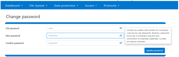
A new password complexity tool-tip message is also displayed, informing the user of safe password selection.
Note that re-login is required after a password change.
On the Users page under Access > Membership and roles > Users, the Action drop-down list on the now also contains a Reset Password option:
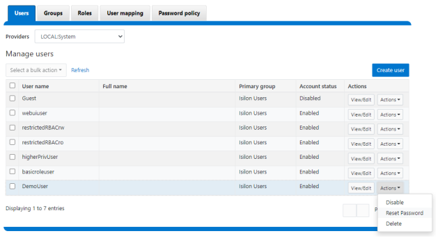
The successful reset confirmation pop-up offers both a show and copy option, while informing the cluster administrator to share the new password with the user, and for them to change their password during their next login:
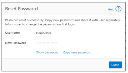
The Create user page now provides an additional field that requires password confirmation. Additionally, the password complexity tool-tip message is also displayed:
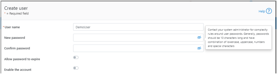
The redesigned Edit user details page no longer provides a field to edit the password directly:
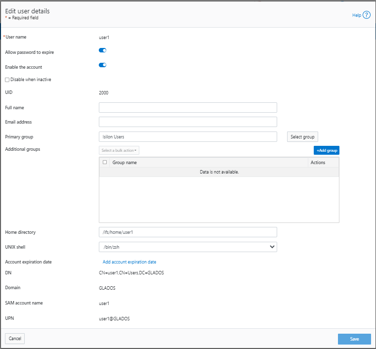
Instead, the Action drop-down list on the Users page now contains a Reset Password option.
Author: Nick Trimbee

OneFS WebUI Single Sign-on Configuration and Deployment
Thu, 20 Jul 2023 18:27:32 -0000
|Read Time: 0 minutes
In the first article in this series, we took a look at the architecture of the new OneFS WebUI SSO functionality. Now, we move on to its provisioning and setup.
SSO on PowerScale can be configured through either the OneFS WebUI or CLI. OneFS 9.5 debuts a new dedicated WebUI SSO configuration page under Access > Authentication Providers > SSO. Alternatively, for command line afficionados, the CLI now includes a new isi auth sso command set.
Here is the overall configuration flow:
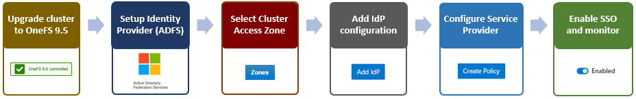
1. Upgrade to OneFS 9.5
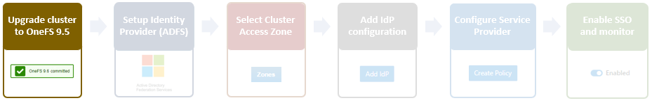
First, ensure the cluster is running OneFS 9.5 or a later release. If upgrading from an earlier OneFS version, note that the SSO service requires this upgrade to be committed prior to configuration and use.
Next, configure an SSO administrator. In OneFS, this account requires at least one of the following privileges:
| Privilege | Description |
|---|---|
ISI_PRIV_LOGIN_PAPI | Required for the admin to use the OneFS WebUI to administer SSO |
ISI_PRIV_LOGIN_SSH | Required for the admin to use the OneFS CLI through SSH to administer SSO |
ISI_PRIV_LOGIN_CONSOLE | Required for the admin to use the OneFS CLI on the serial console to administer SSO |
The user account used for identity provider management should have an associated email address configured.
2. Setup Identity Provider
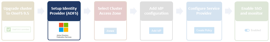
OneFS SSO activation also requires having a suitable identity provider (IdP), such as ADFS, provisioned and available before setting up OneFS SSO.
ADFS can be configured through either the Windows GUI or command shell, and detailed information on the deployment and configuration of ADFS can be found in the Microsoft Windows Server documentation.
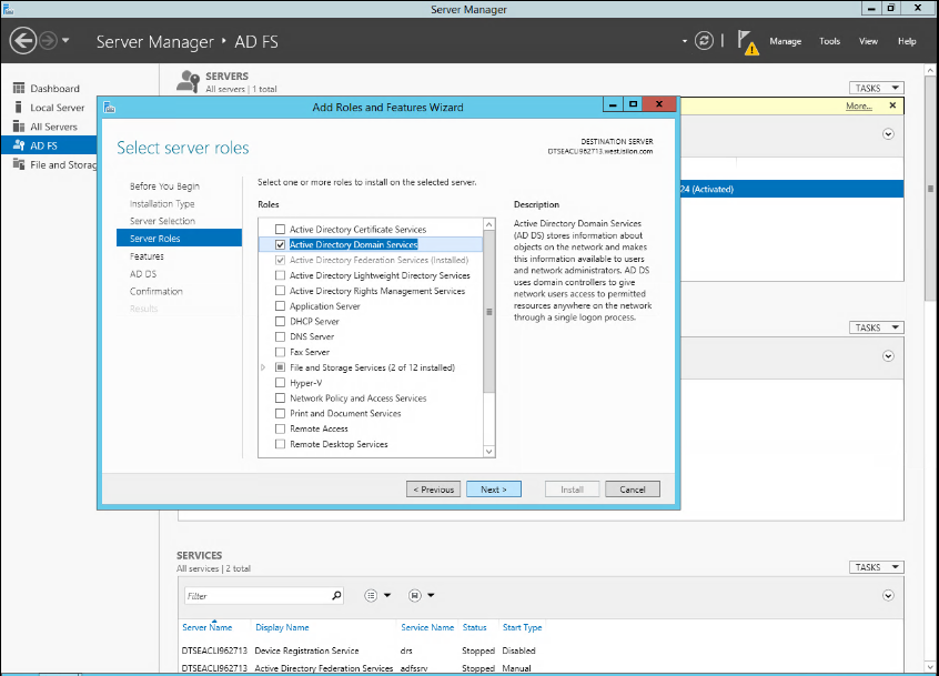
The Windows remote desktop utility (RDP) can be used to provision, connect to, and configure an ADFS server.
- When connected to ADFS, configure a rule defining access. For example, the following command line syntax can be used to create a simple rule that permits all users to log in:
$AuthRules = @"
@RuleTemplate="AllowAllAuthzRule" => issue(Type = "http://schemas.microsoft.com/
authorization/claims/permit", Value="true");
"@
or from the ADFS UI:
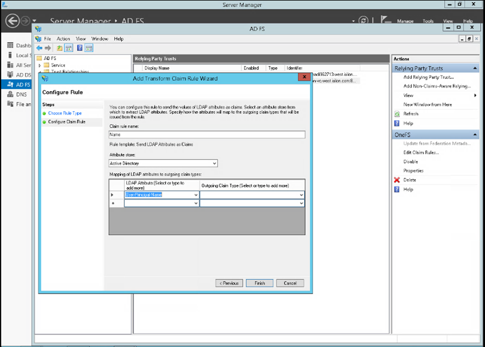
Note that more complex rules can be crafted to meet the particular requirements of an organization. - Create a rule parameter to map the Active Directory user email address to the SAML NameID.
$TransformRules = @" @RuleTemplate = "LdapClaims" @RuleName = "LDAP mail" c:[Type == "http://schemas.microsoft.com/ws/2008/06/identity/claims/ windowsaccountname", Issuer == "AD AUTHORITY"] => issue(store = "Active Directory", types = ("http://schemas.xmlsoap.org/ws/2005/05/identity/claims/ emailaddress"), query = ";mail;{0}", param = c.Value); @RuleTemplate = "MapClaims" @RuleName = "NameID" c:[Type == "http://schemas.xmlsoap.org/ws/2005/05/identity/claims/emailaddress"] => issue(Type = "http://schemas.xmlsoap.org/ws/2005/05/identity/claims/ nameidentifier", Issuer = c. Issuer, OriginalIssuer = c.OriginalIssuer, Value = c.Value, ValueType = c.ValueType, Properties["http://schemas.xmlsoap.org/ws/2005/05/identity / claimproperties/format"] = "urn:oasis:names:tc:SAML:1.1:nameid-format:emailAddress"); "@ - Configure AD to trust the OneFS WebUI certificate.
- Create the relying party trust.
Add-AdfsRelyingPartyTrust -Name <cluster-name>\
     -MetadataUrl "https://<cluster-node-
ip>:8080/session/1/saml/metadata" \
     -IssuanceAuthorizationRules $AuthRules -IssuanceTransformRules
$TransformRules
or from Windows Server Manager:
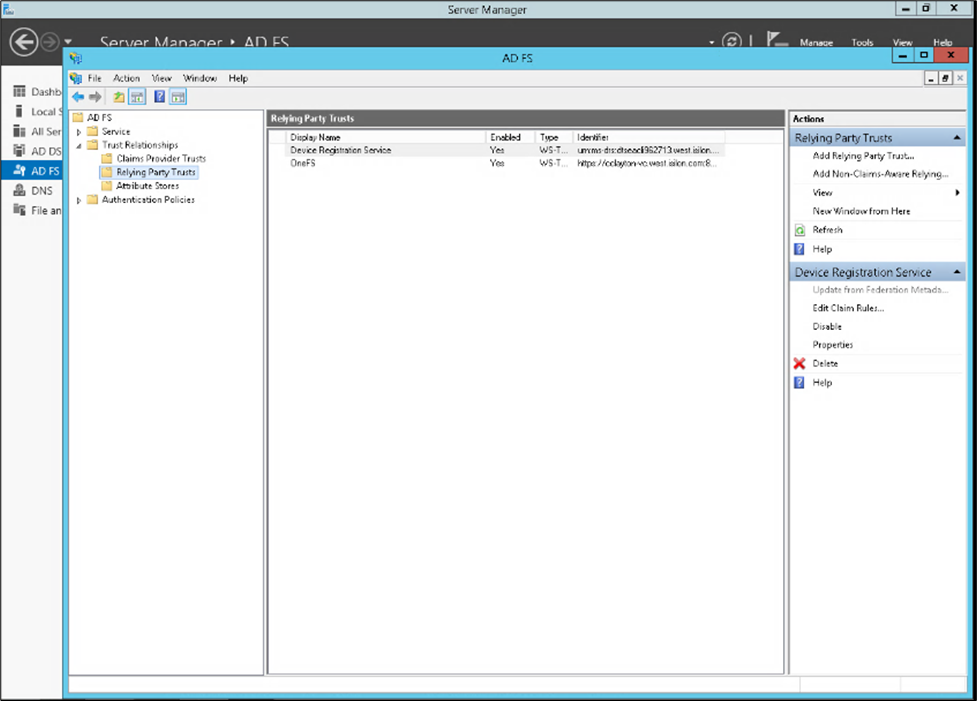
3. Select Access Zone
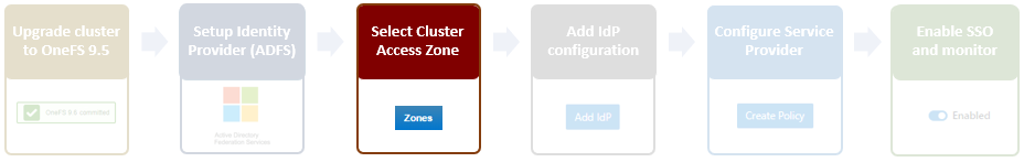
Because OneFS SSO is zone-aware, the next step involves choosing the access zone to configure. Go to Access > Authentication providers > SSO, select an access zone (that is, the system zone), and click Add IdP.
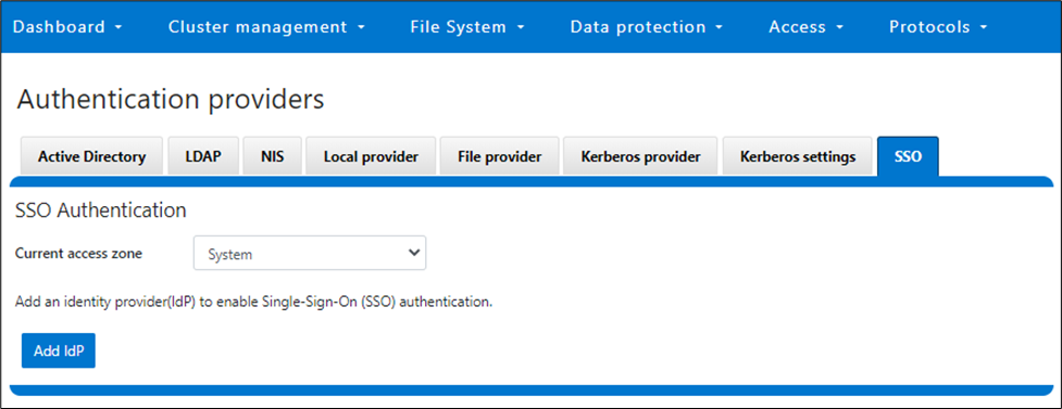
Note that each of a cluster’s access zone or zones must have an IdP configured for it. The same IdP can be used for all the zones, but each access zone must be configured separately.
4. Add IdP Configuration
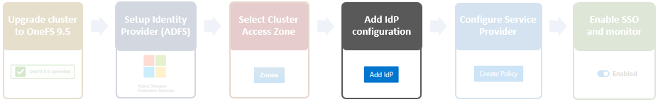
In OneFS 9.5 and later, the WebUI SSO configuration is a wizard-driven, “guided workflow” process involving the following steps:

First, go to Access > Authentication providers > SSO, select an access zone (that is, the system zone), and then click Add IdP.

On the Add Identity Provider page, enter a unique name for the IdP. For example, Isln-IdP1 in this case:
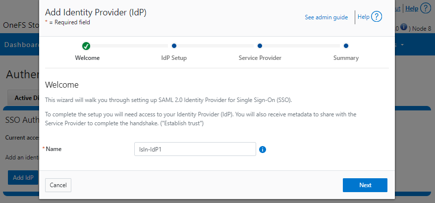
When done, click Next, select the default Upload metadata XML option, and browse to the XML file downloaded from the ADFS system:
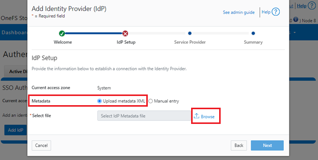
Alternatively, if the preference is to enter the information by hand, select Manual entry and complete the configuration form fields:
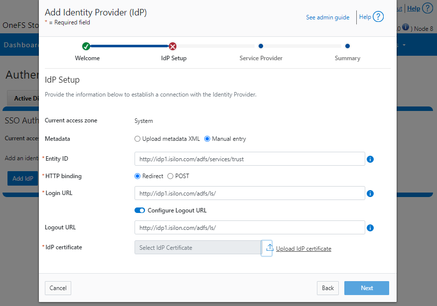
If the manual entry method is selected, you must have the IdP certificate ready to upload. With the manual entry option, the following information is required:
| Field | Description |
|---|---|
Binding | Select POST or Redirect binding. |
Entity ID | Unique identifier of the IdP as configured on the IdP. For example: http://idp1.isilon.com/adfs/services/trust |
Login URL | Log in endpoint for the IdP. For example: http://idp1.isilon.com/adfs/ls/ |
Logout URL | Log out endpoint for the IdP. For example: http://idp1.example.com/adfs/ls/ |
Signing Certificate | Provide the PEM encoded certificate obtained from the IdP. This certificate is required to verify messages from the IdP. |
Upload the IdP certificate:
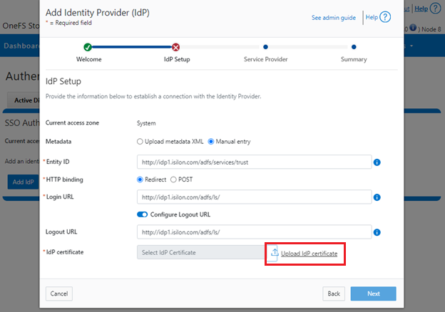
For example:
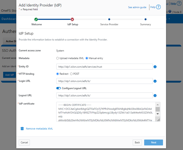
Repeat this step for each access zone in which SSO is to be configured.
When complete, click Next to move on to the service provider configuration step.
5. Configure Service Provider
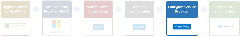
On the Service Provider page, confirm that the current access zone is carried over from the previous page.
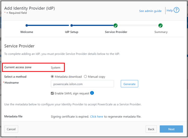
Select Metadata download or Manual copy, depending on the chosen method of entering OneFS details about this service provider (SP) to the IdP.
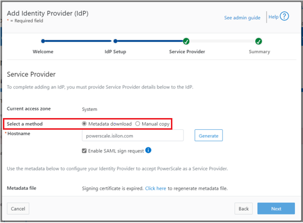
Provide the hostname or IP address for the SP for the current access zone.
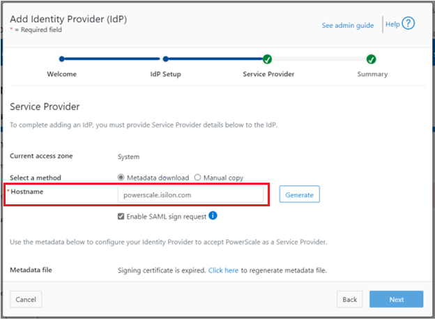
Click Generate to create the information (metadata) about OneFS and this access zone for use in configuring the IdP.
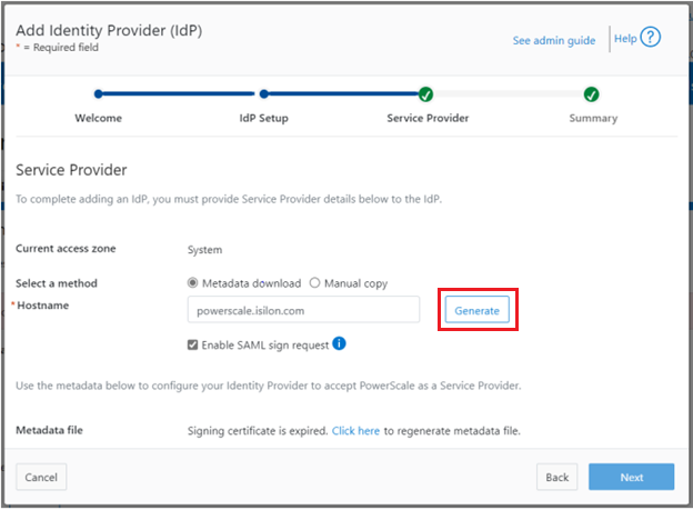
This generated information can now be used to configure the IdP (in this case, Windows ADFS) to accept requests from PowerScale as the SP and its configured access zone.
As shown, the WebUI page provides two methods for obtaining the information:
| Method | Action |
|---|---|
Metadata download | Download the XML file that contains the signing certificate, etc. |
Manual copy | Select Copy Link in the lower half of the form to copy the information to the IdP. |
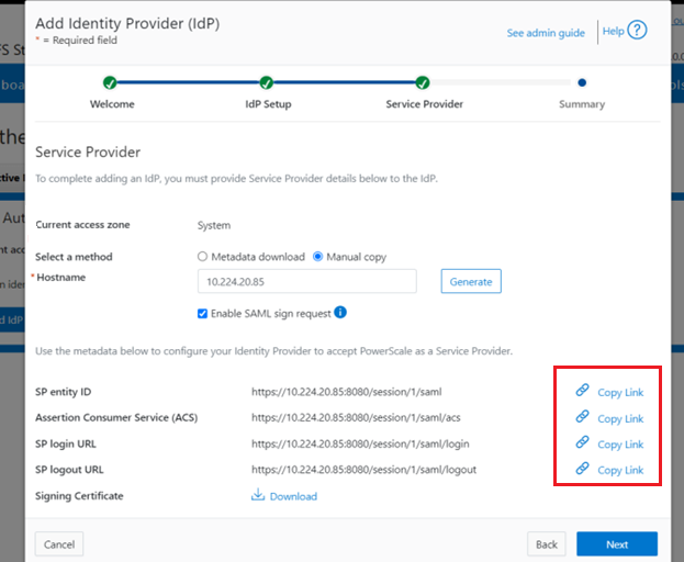
Next, download the Signing Certificate.
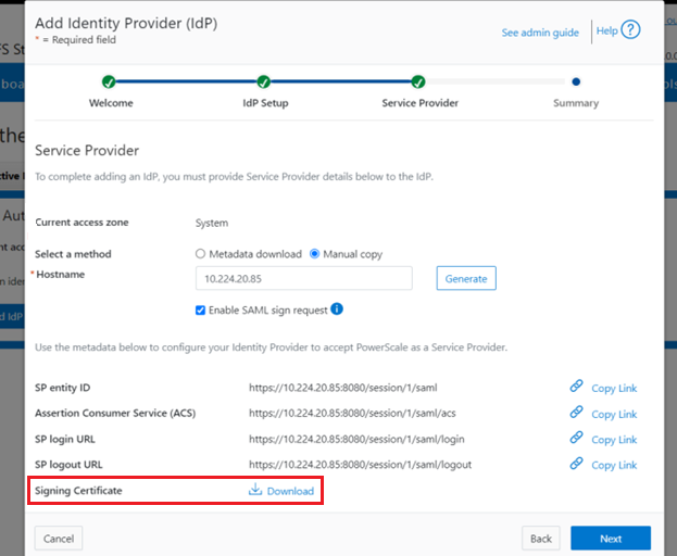
When completed, click Next to finish the configuration.
6. Enable SSO and Verify Operation

Once the IdP and SP are configured, a cluster admin can enable SSO per access zone through the OneFS WebUI by going to Access > Authentication providers > SSO. From here, select the access zone and select the toggle to enable SSO:
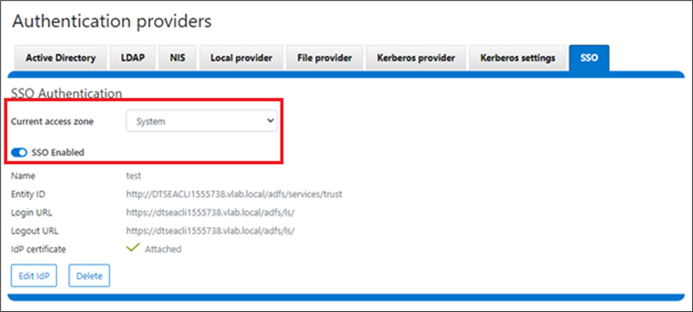
Or from the OneFS CLI, use the following syntax:
# isi auth sso settings modify --sso-enabled 1
Author: Nick Trimbee

OneFS WebUI Single Sign-on
Thu, 20 Jul 2023 16:32:13 -0000
|Read Time: 0 minutes
The Security Assertion Markup Language (SAML) is an open standard for sharing security information about identity, authentication, and authorization across different systems. SAML is implemented using the Extensible Markup Language (XML) standard for sharing data. The SAML framework enables single sign-on (SSO), which in turn allows users to log in once, and their login credential can be reused to authenticate with and access other different service providers. It defines several entities including end users, service providers, and identity providers, and is used to manage identity information. For example, the Windows Active Directory Federation Services (ADFS) is one of the ubiquitous identity providers for SAML contexts.
| Entity | Description |
|---|---|
End user | Requires authentication prior to being allowed to use an application. |
Identity provider (IdP) | Performs authentication and passes the user's identity and authorization level to the service provider—for example, ADFS. |
Service provider (SP) | Trusts the identity provider and authorizes the given user to access the requested resource. With SAML 2.0, a PowerScale cluster is a service provider. |
SAML Assertion | XML document that the identity provider sends to the service provider that contains the user authorization. |
OneFS 9.5 introduces SAML-based SSO for the WebUI to provide a more convenient authentication method, in addition to meeting the security compliance requirements for federal and enterprise customers. In OneFS 9.5, the WebUI’s initial login page has been redesigned to support SSO and, when enabled, a new Log in with SSO button is displayed on the login page under the traditional username and password text boxes. For example:
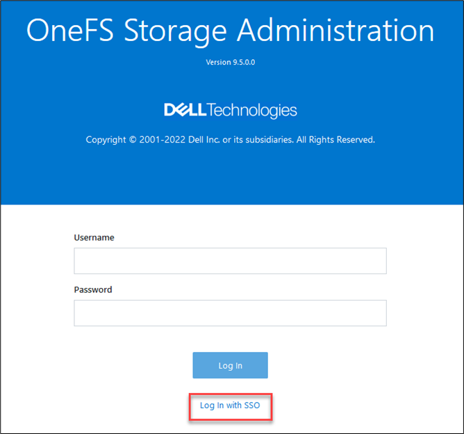
OneFS SSO is also zone-aware in support of multi-tenant cluster configurations. As such, a separate IdP can be configured independently for each OneFS access zone.
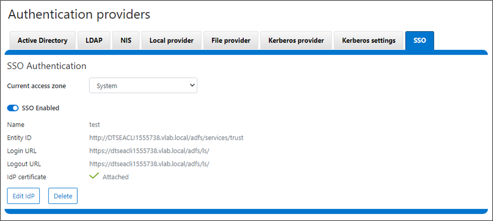
Under the hood, OneFS SSO employs the following high-level architecture:
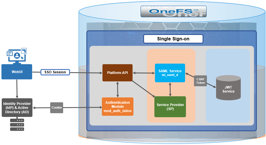
In OneFS 9.5, the SSO operates through HTTP REDIRECT and POST bindings, with the cluster acting as the service provider.
There are three different types of SAML Assertions—authentication, attribute, and authorization decision.
- Authentication assertions prove identification of the user and provide the time the user logged in and what method of authentication they used (that is, Kerberos, two-factor, and so on).
- The attribution assertion passes the SAML attributes to the service provider. SAML attributes are specific pieces of data that provide information about the user.
- An authorization decision assertion states whether the user is authorized to use the service or if the identify provider denied their request due to a password failure or lack of rights to the service.
SAML SSO works by transferring the user’s identity from one place (the identity provider) to another (the service provider). This is done through an exchange of digitally signed XML documents.
A SAML Request, also known as an authentication request, is generated by the service provider to “request” an authentication.
A SAML Response is generated by the identity provider and contains the actual assertion of the authenticated user. In addition, a SAML Response may contain additional information, such as user profile information and group/role information, depending on what the service provider can support. Note that the service provider never directly interacts with the identity provider, with a browser acting as the agent facilitating any redirections.
Because SAML authentication is asynchronous, the service provider does not maintain the state of any authentication requests. As such, when the service provider receives a response from an identity provider, the response must contain all the necessary information.
The general flow is as follows:
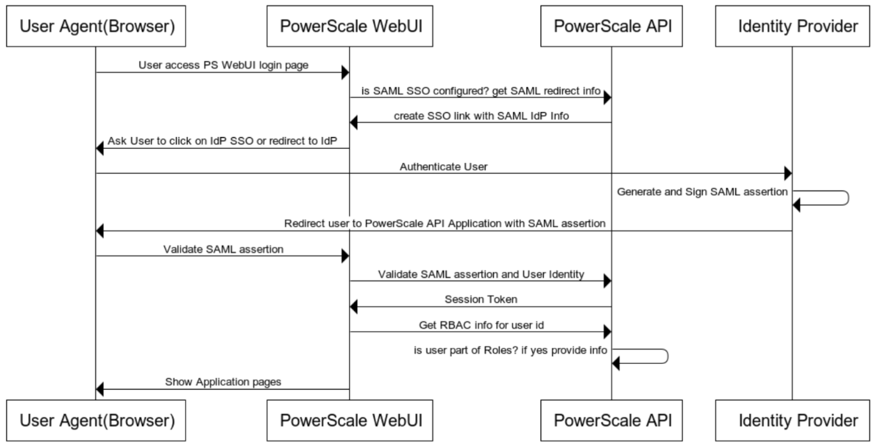
When OneFS redirects a user to the configured IdP for login, it makes an HTTP GET request (SAMLRequest), instructing the IdP that the cluster is attempting to perform a login (SAMLAuthnRequest). When the user successfully authenticates, the IdP responds back to OneFS with an HTTP POST containing an HTML form (SAMLResponse) that indicates whether the login was successful, who logged in, plus any additional claims configured on the IdP.
On receiving the SAMLResponse, OneFS verifies the signature using the public key (X.509 certificate) in to ensure that it really came from its trusted IdP and that none of the contents have been tampered with. OneFS then extracts the identity of the user, along with any other pertinent attributes. At this point, the user is redirected back to the OneFS WebUI dashboard (landing page), as if logged into the site manually.
In the next article in this series, we’ll take a detailed look at the following procedure to deploy SSO on a PowerScale cluster:

Author: Nick Trimbee

OneFS Account Security Policy
Thu, 20 Jul 2023 16:23:21 -0000
|Read Time: 0 minutes
Another of the core security enhancements introduced in OneFS 9.5 is the ability to enforce strict user account security policies. This is required for compliance with both private and public sector security mandates. For example, the account policy restriction requirements expressed within the U.S. military STIG requirements stipulate:
| Requirement | Description |
|---|---|
Delay | The OS must enforce a delay of at least 4 seconds between logon prompts following a failed logon attempt. |
Disable | The OS must disable account identifiers (individuals, groups, roles, and devices) after 35 days of inactivity. |
Limit | The OS must limit the number of concurrent sessions to ten for all accounts and/or account types. |
To directly address these security edicts, OneFS 9.5 adds the following account policy restriction controls:
| Account policy function | Details |
|---|---|
Delay after failed login |
|
Disable inactive accounts |
|
Concurrent session limit |
|
Architecture
OneFS provides a variety of access mechanisms for administering a cluster. These include SSH, serial console, WebUI, and platform API, all of which use different underlying access methods. The serial console and SSH are standard FreeBSD third-party applications and are accounted for per node, whereas the WebUI and pAPI use HTTP module extensions to facilitate access to the system and services and are accounted for cluster-wide. Before OneFS 9.5, there was no common mechanism to represent or account for sessions across these disparate applications.
Under the hood, the OneFS account security policy framework encompasses the following high-level architecture:
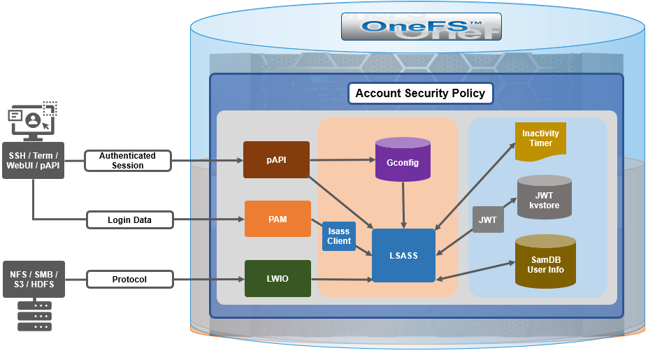
With SSH, there’s no explicit or reliable “log-off” event sent to OneFS, beyond actually disconnecting the connection. As such, accounting for active sessions can be problematic and unreliable, especially when connections time out or unexpectedly disconnect. However, OneFS does include an accounting database that stores records of system activities like user login and logout, which can be queried to determine active SSH sessions. Each active SSH connection has an isi_ssh_d process owned by the account associated with it, and this information can be gathered via standard syscalls. OneFS enumerates the number of SSHD processes per account to calculate the total number of active established sessions. This value is then used as part of the total concurrent administrative sessions limit. Since SSH only supports user access through the system zone, there is no need for any zone-aware accounting.
The WebUI and platform API use JSON web tokens (JWTs) for authenticated sessions. OneFS stores the JWTs in the cluster-wide kvstore, and access policy uses valid session tokens in the kvstore to account for active sessions when a user logs on through the WebUI or pAPI. When the user logs off, the associated token is removed, and a message is sent to JWT service with an explicit log off notification. If a session times out or disconnects, the JWT service will not get an event, but the tokens have a limited, short lifespan, and any expired tokens are purged from the list on a scheduled basis in conjunction with the JWT timer. OneFS enumerates the unique session IDs associated with each user’s JWT tokens in the kvstore to get a number of active WebUI and pAPI sessions to use as part of user’s session limit check.
For serial console access accounting, the process table will have information when an STTY connection is active, and OneFS extrapolates user data from it to determine the session count, similar to ssh with a syscall for process data. There is an accounting database that stores records of system activities like user login and logout, which is also queried for active console sessions. Serial console access is only from the system zone, so there is no need for zone-aware accounting.
An API call retrieves user session data from the process table and kvstore to calculate number of user active sessions. As such, the checking and enforcement of session limits is performed in similar manner to the verification of user privileges for SSH, serial console, or WebUI access.
Delaying failed login reconnections
OneFS 9.5 provides the ability to enforce a configurable delay period. This delay is specified in seconds, after which every unsuccessful authentication attempt results in the user being denied the ability to reconnect to the cluster until after the configured delay period has passed. The login delay period is defined in seconds through the FailedLoginDelayTime global attribute and, by default, OneFS is configured for no delay through a FailedLoginDelayTime value of 0. When a cluster is placed into hardened mode with the STIG policy enacted, the delay value is automatically set to 4 seconds. Note that the delay happens in the lsass client, so that the authentication service is not affected.
The configured failed login delay time limit can be viewed with following CLI command:
# isi auth settings global view
                            Send NTLMv2: No
                      Space Replacement:
                              Workgroup: WORKGROUP
               Provider Hostname Lookup: disabled
                          Alloc Retries: 5
                 User Object Cache Size: 47.68M
                       On Disk Identity: native
                         RPC Block Time: Now
                       RPC Max Requests: 64
                            RPC Timeout: 30s
Default LDAP TLS Revocation Check Level: none
                   System GID Threshold: 80
                   System UID Threshold: 80
                         Min Mapped Rid: 2147483648
                              Group UID: 4294967292
                               Null GID: 4294967293
                               Null UID: 4294967293
                            Unknown GID: 4294967294
                            Unknown UID: 4294967294
                Failed Login Delay Time: Now
               Concurrent Session Limit: 0
Similarly, the following syntax will configure the failed login delay time to a value of 4 seconds:
# isi auth settings global modify --failed-login-delay-time 4s
# isi auth settings global view | grep -i delay
                Failed Login Delay Time: 4s
However, when a cluster is put into STIG hardening mode, the “Concurrent sessions limit” is automatically set to 10.
# isi auth settings global view | grep -i delay
                Failed Login Delay Time: 10s
The delay time after login failure can also be configured from the WebUI under Access > Settings > Global provider settings:
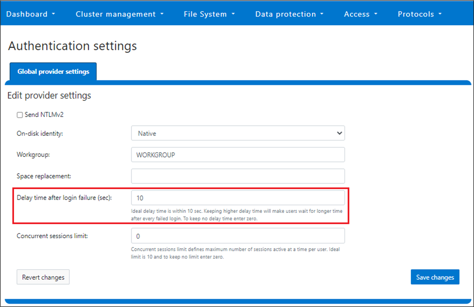
The valid range of the FailedLoginDelayTime global attribute is from 0 to 65535, and the delay time is limited to the same cluster node.
Note that this maximum session limit is only applicable to administrative logins.
Disabling inactive accounts
In OneFS 9.5, any user account that has been inactive for a configurable duration can be automatically disabled. Administrative intervention is required to re-enable a deactivated user account. The last activity time of a user is determined by their previous logon, and a timer runs every midnight during which all “inactive” accounts are disabled. If the last logon record for a user is unavailable, or stale, the timestamp when the account was enabled is taken as their last activity instead. If inactivity tracking is enabled after the last logon (or enabled) time of a user, the inactivity tracking time is considered for inactivity period.
This feature is disabled by default in OneFS, and all users are exempted from inactivity tracking until configured otherwise. However, individual accounts can be exempted from this behavior, and this can be configured through the user-specific DisableWhenInactive attribute. For example:
# isi auth user view user1 | grep -i inactive
   Disable When Inactive: Yes
# isi auth user modify user1 --disable-when-inactive 0
# isi auth user view user1 | grep -i inactive
   Disable When Inactive: No
If a cluster is put into STIG hardened mode, the value for the MaxInactivityDays parameter is automatically reconfigured to 35, meaning a user will be disabled after 35 days of inactivity. All the local users are removed from exemption when in STIG hardened mode.
Note that this functionality is limited to only the local provider and does not apply to file providers.
The inactive account disabling configuration can be viewed from the CLI with the following syntax. In this example, the MaxInactivityDays attribute is configured for 35 days:
# isi auth local view system
                    Name: System
                  Status: active
          Authentication: Yes
   Create Home Directory: Yes
 Home Directory Template: /ifs/home/%U
        Lockout Duration: Now
       Lockout Threshold: 0
          Lockout Window: Now
             Login Shell: /bin/zsh
            Machine Name:
        Min Password Age: Now
        Max Password Age: 4W
     Min Password Length: 15
    Password Prompt Time: 2W
     Password Complexity: -
 Password History Length: 0
  Password Chars Changed: 8
Password Percent Changed: 50
      Password Hash Type: NTHash
     Max Inactivity Days: 35
Inactive account disabling can also be configured from the WebUI under Access > Authentication providers > Local provider:
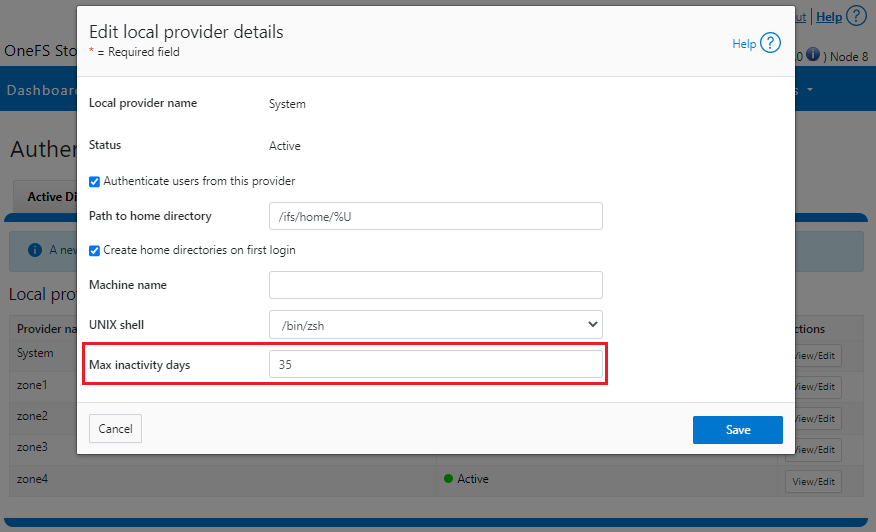
The valid range of the MaxInactivityDays parameter is from 0 to UINT_MAX. As such, the following CLI syntax will configure the maximum number of days a user account can be inactive before it will be disabled to 10 days:
# isi auth local modify system --max-inactivity-days 10
# isi auth local view system | grep -i inactiv
     Max Inactivity Days: 0tem –max-inactivity-days 10
Setting this value to 0 days will disable the feature:
# isi auth local modify system --max-inactivity-days 0
# isi auth local view system | grep -i inactiv
     Max Inactivity Days: 0tem –max-inactivity-days 0
Inactivity account disabling, as well as password expiry, can also be configured granularly, per user account. For example, user1 has a default configuration of the Disable When Inactive threshold set to No.
# isi auth users view user1
                    Name: user1
                      DN: CN=user1,CN=Users,DC=GLADOS
              DNS Domain: -
                  Domain: GLADOS
                Provider: lsa-local-provider:System
        Sam Account Name: user1
                     UID: 2000
                     SID: S-1-5-21-1839173366-2940572996-2365153926-1000
                 Enabled: Yes
                 Expired: No
                  Expiry: -
                  Locked: No
                   Email: -
                   GECOS: -
           Generated GID: No
           Generated UID: No
           Generated UPN: Yes
           Primary Group
                          ID: GID:1800
                        Name: Isilon Users
          Home Directory: /ifs/home/user1
        Max Password Age: 4W
        Password Expired: No
         Password Expiry: 2023-06-15T17:45:55
       Password Last Set: 2023-05-18T17:45:55
        Password Expired: No
              Last Logon: -
                   Shell: /bin/zsh
                     UPN: user1@GLADOS
User Can Change Password: Yes
   Disable When Inactive: No
The following CLI command will activate the account inactivity disabling setting and enable password expiry for the user1 account:
# isi auth users modify user1 --disable-when-inactive Yes --password-expires Yes
Inactive account disabling can also be configured from the WebUI under Access > Membership and roles > Users > Providers:
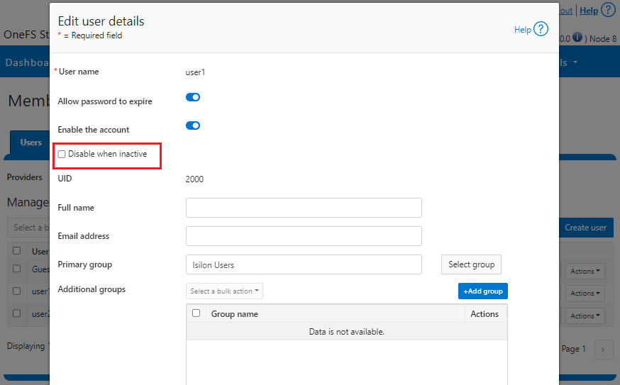
Limiting concurrent sessions
OneFS 9.5 can limit the number of administrative sessions active on a OneFS cluster node, and all WebUI, SSH, pAPI, and serial console sessions are accounted for when calculating the session limit. The SSH and console session count is node-local, whereas WebUI and pAPI sessions are tracked cluster-wide. As such, the formula used to calculate a node’s total active sessions is as follows:
Total active user sessions on a node = Total WebUI and pAPI sessions across the cluster + Total SSH and Console sessions on the node
This feature leverages the cluster-wide session management through JWT for calculating the total number of sessions on a cluster’s node. By default, OneFS 9.5 has no configured limit, and the Concurrent Session Limit parameter has a value of 0. For example:
# isi auth settings global view
                            Send NTLMv2: No
                      Space Replacement:
                              Workgroup: WORKGROUP
               Provider Hostname Lookup: disabled
                          Alloc Retries: 5
                 User Object Cache Size: 47.68M
                       On Disk Identity: native
                         RPC Block Time: Now
                       RPC Max Requests: 64
                            RPC Timeout: 30s
Default LDAP TLS Revocation Check Level: none
                   System GID Threshold: 80
                   System UID Threshold: 80
                         Min Mapped Rid: 2147483648
                              Group UID: 4294967292
                               Null GID: 4294967293
                               Null UID: 4294967293
                            Unknown GID: 4294967294
                            Unknown UID: 4294967294
                Failed Login Delay Time: Now
               Concurrent Session Limit: 0
The following CLI syntax will configure Concurrent Session Limit to a value of 5:
# isi auth settings global modify –-concurrent-session-limit 5
# isi auth settings global view | grep -i concur
                Concurrent Session Limit: 5
Once the session limit has been exceeded, attempts to connect, in this case as root through SSH, will be met with the following Access denied error message:
login as: root
Keyboard-interactive authentication prompts from server:
| Password:
End of keyboard-interactive prompts from server
Access denied
password:
The concurrent sessions limit can also be configured from the WebUI under Access > Settings > Global provider settings:
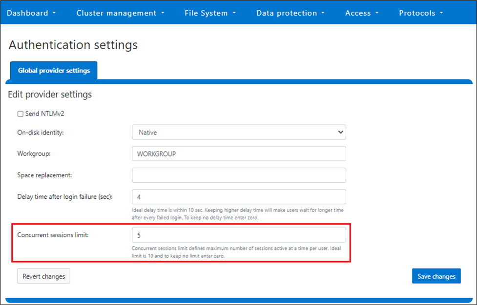
However, when a cluster is put into STIG hardening mode, the concurrent session limit is automatically set to a maximum of 10 sessions.
Note that this maximum session limit is only applicable to administrative logins.
Performance
Disabling an account after a period of inactivity in OneFS requires a SQLite database update every time a user has successfully logged on to the OneFS cluster. After a successful logon, the time to logon is recorded in the database, which is later used to compute the inactivity period.
Inactivity tracking is disabled by default in OneFS 9.5, but can be easily enabled by configuring the MaxInactivityDays attribute to a non-zero value. In cases where inactivity tracking is enabled and many users are not exempt from inactivity tracking, a significant number of logons within a short period of time can generate significant SQLite database requests. However, OneFS consolidates multiple database updates during user logon to a single commit to minimize the overall load.
Troubleshooting
When it comes to troubleshooting OneFS account security policy configurations, there are these main logfiles to check:
- /var/log/lsassd.log
- /var/log/messages
- /var/log/isi_papi_d.log
For additional reporting detail, debug level logging can be enabled on the lsassd.log file with the following CLI command:
# /usr/likewise/bin/lwsm set-log-level lsass – debug
When finished, logging can be returned to the regular error level:
# /us/likewise/bin/lwsm set-log-level lsass - error
Author: Nick Trimbee

OneFS 9.5 Performance Enhancements for Video Editing

Wed, 19 Jul 2023 18:16:59 -0000
|Read Time: 0 minutes
Of the many changes in OneFS 9.5, the most exciting are the performance enhancements on the NVMe-based PowerScale nodes: F900 and F600. These performance increases are the result of some significant changes “under-the-hood” to OneFS. In the lead-up to the National Association of Broadcasters show last April, I wanted to qualify how much of a difference the extra performance would make for Adobe Premiere Pro video editing workflows. Adobe is one of Dell’s biggest media software partners, and Premiere Pro is crucial to all sorts of media production, from broadcast to cinema.
The awesome news is that the changes to OneFS make a big difference. I saw 40% more video streams with the software upgrade: up to 140 streams of UHD ProRes422 from a single F900 node!
Changes to OneFS
Broadly speaking, there were changes to three areas in OneFS that resulted in the performance boost in version 9.5. These areas are L2 cache, backend networking, and prefetch.
L2 cache -- Being smart about how and when to bypass L2 cache and read directly from NVMe is one part of the OneFS 9.5 performance story. PowerScale OneFS clusters maintain a globally accessible L2 cache for all nodes in the cluster. Manipulating L2 cache can be “expensive” computationally speaking. During a read, the cluster needs to determine what data is in cache, whether the read should be added to cache, and what data should be expired from cache. NVMe storage is so performant that bypassing the L2 cache and reading data directly from NVMe frees up cluster resources. Doing so results in even faster reads on nodes that support it.
Backend networking -- OneFS uses a private backend network for internode communication. With the massive performance of NVMe based storage and the introduction of 100 GbE, limits were getting reached on this private network. OneFS 9.5 gets around these limitations with a custom multichannel approach (similar in concept to nconnect from the NFS world for the Linux folks out there). In OneFS 9.5, the connection channels on the backend network are bonded in a carefully orchestrated way to parallelize some aspects, while still keeping a predictable message ordering.
Prefetch -- The last part of the performance boost for OneFS 9.5 comes from improved file prefetch. How OneFS prefetches file system metadata was reworked to more optimally read ahead at the different depths of the metadata tree. Efficiency was improved and “jitter” between file system processes minimized.
Our lab setup
First a little background on PowerScale and OneFS. PowerScale is the updated name for the Isilon product line. The new PowerScale nodes are based on Dell servers with compute, RAM, networking, and storage. PowerScale is a scale-out, clustered network-attached-storage (NAS) solution. To build a OneFS file system, PowerScale nodes are joined to create cluster. The cluster creates a single NAS file system with the aggregate resources of all the nodes in the cluster. Client systems connect using a DNS name, and OneFS SmartConnect balances client connections between the various nodes. No matter which node the client connects to, that client has the potential to access all the data on the entire cluster. Further, the client systems benefit from the all the nodes acting in concert.
Even before the performance enhancements in OneFS 9.5, the NVMe-based PowerScale nodes were speedy, so a robust lab environment was going to be needed to stress the system. For this particular set of tests, I had access to 16 workstations running the latest version of Adobe Premiere Pro 2023. Each workstation ran Windows 10 with Nvidia GPU, Intel processor, and 10 GbE networking. On the storage side, the tests were performed against a minimum sized 3-node F900 PowerScale cluster with 100 GbE networking.
Adobe Premiere Pro excels at compressed video editing. The trick with compressed video is that an individual client workstation will get overwhelmed long before the storage system. As such, it is critical to evaluate whether any dropped frames are the result of storage or an overwhelmed workstation. A simple test is to take a single workstation and start playing back parallel compressed video streams, such as ProRes 422. Keeping a close watch on the workstation performance monitors, at a certain point CPU and GPU usage will spike and frames will drop. This test will show the maximum number of streams that a single workstation can handle. Because this test is all about storage performance, keeping the number of streams per workstation to a healthy range takes individual workstation performance out of the equation.
I settled on 10x streams of ProRes 422 UHD video running at 30 frames per second per workstation. Each individual video stream was ~70 MBps (560mbps). Running ten of these streams meant each workstation was pulling around 700 MBps (though with Premiere Pro prefetching this number was closer to 800 MBps). With this number of video streams, the workstation wasn’t working too hard and it was well within what would fit down a 10 GbE network pipe.
Running some quick math here, 16 workstations each pulling 800-ish MBps works out to about 12.5 GBps of total throughput. This throughput is not enough throughput to overwhelm even a small 3-node F900 cluster. In order to stress the system, all 16 workstations were manually pointed to single 100 GbE port on a single F900 node. Due to the clustered nature of OneFS, the clients will get benefit from the entire cluster. But even with the rest of the cluster behind it, at a certain point, a single F900 node is going to get overwhelmed.
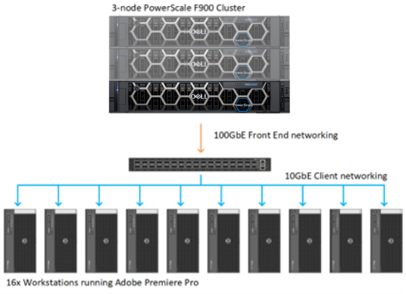
Figure 1. OneFS Lab configuration
Test methodology
The first step was to import test media for playback. Each workstation accessed its own unique set of 10x one-hour long UHD ProRes422 clips. Then a separate Premiere Pro project was created for each workstation with 10 simultaneous layers of video. The plan was to start playback one by one on each workstation and see where the tipping point was for that single PowerScale F900 node. The test was to be run first with OneFS 9.4 and then with OneFS 9.5.
Adobe Premiere Pro has a debug overlay called DogEars. In addition to showing dropped frames, DogEars provides some useful metrics about how “healthy” video playback is in Premiere Pro. Even before a system starts to drop frames, latency spikes and low prefetch buffers show when Premiere Pro is struggling to sustain playback.
The metrics in DogEars that I was focused on were the following:
Dropped frames: This metric is obvious, dropped frames are unacceptable. However, at times Premiere Pro will show single digit dropped frames at playback start.
FramePrefetchLatency: This metric only shows up during playback. The latency starts high while the prefetch frame buffer is filling. When that buffer gets up to slightly over 300 frames, the latency drops down to around 20 to 30 milliseconds. When the storage system was overwhelmed, this prefetch latency goes well above 30 milliseconds and stays there.
CompleteAheadOfPlay: This metric also only shows up during playback. The number of frames creeps up during playback and settles in at slightly over 300 prefetched frames. The FramePrefetchLatency above will be high (in the 100ms range or so) until the 300 frames are prefetched, at which point the latency will drop down to 30ms or lower. When the storage system is stressed, Premiere Pro is never able to fill this prefetch buffer, and it never gets up to the 300+ frames.

Figure 2. Premiere Pro with Dogears overlay
Test results
With the test environment configured and the individual projects loaded, it was time to see what the system could provide.
With the PowerScale cluster running OneFS 9.4, playback was initiated on each Adobe Premiere workstation. Keep in mind that all the workstations were artificially pointed to a single node in this 3-node F900 cluster. That single F900 node running OneFS 9.4 could handle 10x of the workstations, each playing back 10x UHD streams. That’s 100x streams of UHD ProRes 422 video from one node. Not too shabby.
At 110x streams (11 workstations), no frames were dropped, but the CompleteAheadOfPlay number on all the workstations started to go below 300. Also, the FramePreFetchLatency spiked to over 100 milliseconds. Clearly, the storage node was unable to provide more performance.
After reproducing these results several times to confirm accuracy, we unmounted the storage from each workstation and upgraded the F900 cluster to OneFS 9.5. Time to see how much of a difference the OneFS 9.5 performance boost would make for Premiere Pro.
As before, each workstation loaded a unique project with unique ProRes media. At 100x streams of video, playback chugged along fine. Time to load up additional streams and see where things break. 110, 120, 130, 140… playback from the single F900 node continued to chug along with no drops and acceptable latency. It was only at 150 streams of video that playback began to suffer. By this time, that single F900 node was pumping close to 10GBps out of that single 100 GbE NIC port. These 14x workstations were not entirely saturating the connection, but getting close. And the performance was a 40% bump from the OneFS 9.4 numbers. Impressive.
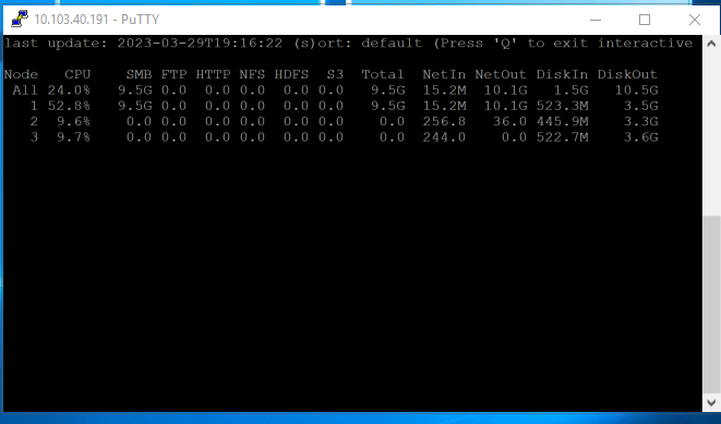
Figure 3. isi statistics output with 140 streams of video from a single node
These results exceeded my expectations going into the project. Getting a 40% performance boost with a code upgrade to existing hardware is impressive. This increase lined up with some of the benchmarking tools used by engineering. But performance from a benchmark tool vs. a real-world application are often two entirely different things. Benchmark tools are particularly inaccurate for video playback where small increases in latency can result in unacceptable results. Because Adobe Premiere is one of the most widely used applications with PowerScale storage, it made sense as a test platform to gauge these differences. For more information about PowerScale storage and media, check out https://Dell.to/media.
Click here to learn more about the author, Gregory Shiff

Success with Dell PowerScale and Baselight by FilmLight
Wed, 19 Jul 2023 18:19:27 -0000
|Read Time: 0 minutes
In my role as technical lead for media workflows at Dell Technologies, I’m fortunate to partner with companies making some of the best tools for creatives. FilmLight is undeniably one of those companies. Baselight by FilmLight is used in the highest end of feature film production. I was eager to put the latest all-flash PowerScale OneFS nodes to the test and see how those storage nodes could support Baselight workflows. I’m pleased to say that PowerScale supports Baselight very well, and I’m able to share best practices for integrating PowerScale into Baselight environments.
Baselight is a color grading and image-processing system that is widely used in cinematic production. Traditionally, Baselight DI workflows are the domain of SAN or block storage. The journey towards supporting modern DI workflows on PowerScale started with OneFS’s support of NFS-over-RDMA. Using the RDMA protocol with PowerScale all flash storage allows for high throughput workflows that are unobtainable with TCP. Using RDMA for media applications is well documented in the blog and white paper: NFS over RDMA for Media Workflows.
With successful RDMA testing on other color correction software complete, I was confident that we could add Baselight to the list of supported platforms. The time seemed ripe, and FilmLight agreed to work with us on getting it done. In partnership with the FilmLight team in LA, we got Baselight One up and running in the Seattle media lab.
FilmLightOS already has a driver installed that supports RDMA for the NIC in the workstation. This made configuration easy, because no additional software had to be installed to support the protocol (at least in our case). While RDMA remains the best choice for using PowerScale with Baselight, not all networks can support RDMA. The good news here is that there is another option: nconnect.
The Linux distribution that Baselight runs on also supports the NFS nconnect mount option. Nconnect allows for multiple TCP connections between the Baselight client and the PowerScale storage. Testing with nconnect demonstrated enough throughput to support 8K uncompressed playback from PowerScale. While RDMA is preferred, it is not an absolute requirement.
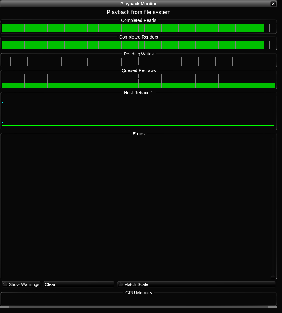
With the storage mounted and performing as expected, we set about adjusting Baselight threads and DirectIO settings to optimize the interaction of Baselight and PowerScale. The results of this testing showed that increasing BaseLight’s thread count to 16 improved performance. (These threads were unrelated to the nconnect connections mentioned above.) DirectIO is a mechanism that bypasses some caching layers in Linux. DirectIO improved Baselight’s write performance and degraded read performance. Thankfully, Baselight is flexible enough to selectively enable DirectIO only for writes.
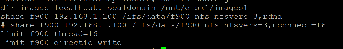
PowerScale is an easy win for Baselight One. However, Baselight also comes in other variations: Baselight Two and Baselight X. These versions of Baselight have separate processing nodes and host UI devices to tackle the most challenging workflows. These Baselight systems share configuration files that can cause issues with how the storage is mounted on the processing nodes as compared to the host UI nodes. When using RDMA, the processing nodes will use an RDMA mount while the host UI will use TCP. Working with the FilmLight team in LA, changes were made to support separate mount options for the processing nodes vs, host UI node.
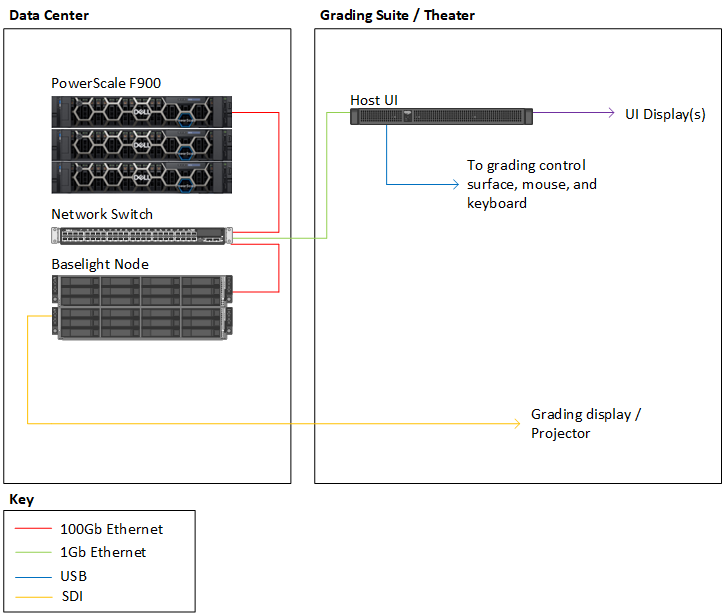
Getting to know Baselight and partnering with FilmLight on this project was highly satisfying. It would not have been easy to understand the finer intricacies of how Baselight interacts with storage without their help (the rendering and caching mechanisms within Baselight are awesome).
For more details about how to use PowerScale with Baselight, check out the full white paper: PowerScale OneFS: Baselight by FilmLight Best Practices and Configuration.
For more information, and the latest content on Dell Media and Entertainment storage solutions, visit us online.

OneFS Restricted Shell—Log Viewing and Recovery
Tue, 27 Jun 2023 20:37:27 -0000
|Read Time: 0 minutes
Complementary to the restricted shell itself, which was covered in the previous article in this series, OneFS 9.5 also sees the addition of a new log viewer, plus a recovery shell option.
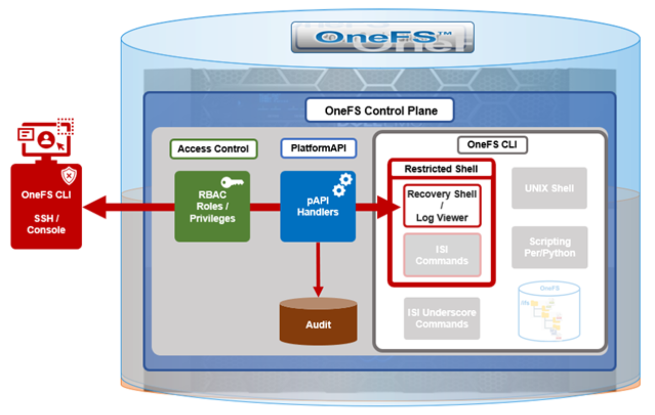
The new isi_log_access CLI utility enables an SSH user to read, page, and query the log files in the /var/log directory. The ability to run this tool is governed by the user’s role being granted the ISI_PRIV_SYS_SUPPORT role-based access control (RBAC) privilege.
OneFS RBAC is used to explicitly limit who has access to the range of cluster configurations and operations. This granular control allows for crafting of administrative roles, which can create and manage the various OneFS core components and data services, isolating each to specific security roles or to admin only, and so on.
In this case, a cluster security administrator selects the access zone, creates a zone-aware role within it, assigns the ISI_PRIV_SYS_SUPPORT privileges for isi_log_access use, and then assigns users to the role.
Note that the integrated OneFS AuditAdmin RBAC role does not contain the ISI_PRIV_SYS_SUPPORT privileges by default. Also, the integrated RBAC roles cannot be reconfigured:
# isi auth roles modify AuditAdmin --add-priv=ISI_PRIV_SYS_SUPPORT
The privileges of built-in role AuditAdmin cannot be modified
Therefore, the ISI_PRIV_SYS_SUPPORT role has to be added to a custom role.
For example, the following CLI syntax adds the user usr_admin_restricted to the rl_ssh role and adds the privilege ISI_PRIV_SYS_SUPPORT to the rl_ssh role:
# isi auth roles modify rl_ssh --add-user=usr_admin_restricted
# isi auth roles modify rl_ssh --add-priv=ISI_PRIV_SYS_SUPPORT
# isi auth roles view rl_ssh
        Name: rl_ssh
 Description: -
     Members: u_ssh_restricted
              u_admin_restricted
  Privileges
              ID: ISI_PRIV_LOGIN_SSH
      Permission: r
             ID: ISI_PRIV_SYS_SUPPORT
      Permission: r
The usr_admin_restricted user could also be added to the AuditAdmin role:
# isi auth roles modify AuditAdmin --add-user=usr_admin_restricted
# isi auth roles view AuditAdmin | grep -i member
     Members: usr_admin_restricted
The isi_log_access tool supports the following command options and arguments:
| Option | Description |
|---|---|
–grep | Match a pattern against the file and display on stdout |
–help | Display the command description and usage message |
–list | List all the files in the /var/log tree |
–less | Display the file on stdout with a pager in secure_mode |
–more | Display the file on stdout with a pager in secure_mode |
–view | Display the file on stdout |
–watch | Display the end of the file and new content as it is written |
–zgrep | Match a pattern against the unzipped file contents and display on stdout |
–zview | Display an unzipped version of the file on stdout |
Here the u_admin_restricted user logs in to the SSH and runs the isi_log_access utility to list the /var/log/messages log file:
# ssh u_admin_restricted@10.246.178.121
 (u_admin_restricted@10.246.178.121)
 Password:
 Last login: Wed May  3 18:02:18 2023 from 10.246.159.107
 Copyright (c) 2001-2023 Dell Inc. or its subsidiaries. All Rights Reserved.
 Copyright (c) 1992-2018 The FreeBSD Project.
 Copyright (c) 1979, 1980, 1983, 1986, 1988, 1989, 1991, 1992, 1993, 1994
         The Regents of the University of California. All rights reserved.
PowerScale OneFS 9.5.0.0
Allowed commands are
         clear ...
         isi ...
         isi_recovery_shell ...
         isi_log_access ...
         exit
         logout
 # isi_log_access –list
 LAST MODIFICATION TIME         SIZE       FILE
 Mon Apr 10 14:22:18 2023       56         alert.log
 Fri May  5 00:30:00 2023       62         all.log
 Fri May  5 00:30:00 2023       99         all.log.0.gz
 Fri May  5 00:00:00 2023       106        all.log.1.gz
 Thu May  4 00:30:00 2023       100        all.log.2.gz
 Thu May  4 00:00:00 2023       107        all.log.3.gz
 Wed May  3 00:30:00 2023       99         all.log.4.gz
 Wed May  3 00:00:00 2023       107        all.log.5.gz
 Tue May  2 00:30:00 2023       100        all.log.6.gz
 Mon Apr 10 14:22:18 2023       56         audit_config.log
 Mon Apr 10 14:22:18 2023       56         audit_protocol.log
 Fri May  5 17:23:53 2023       82064      auth.log
 Sat Apr 22 12:09:31 2023       10750      auth.log.0.gz
 Mon Apr 10 15:31:36 2023       0          bam.log
 Mon Apr 10 14:22:18 2023       56         boxend.log
 Mon Apr 10 14:22:18 2023       56         bwt.log
 Mon Apr 10 14:22:18 2023       56         cloud_interface.log
 Mon Apr 10 14:22:18 2023       56         console.log
 Fri May  5 18:20:32 2023       23769      cron
 Fri May  5 15:30:00 2023       8803       cron.0.gz
 Fri May  5 03:10:00 2023       9013       cron.1.gz
 Thu May  4 15:00:00 2023       8847       cron.2.gz
 Fri May  5 03:01:02 2023       3012       daily.log
 Fri May  5 00:30:00 2023       101        daily.log.0.gz
 Fri May  5 00:00:00 2023       1201       daily.log.1.gz
 Thu May  4 00:30:00 2023       102        daily.log.2.gz
 Thu May  4 00:00:00 2023       1637       daily.log.3.gz
 Wed May  3 00:30:00 2023       101        daily.log.4.gz
 Wed May  3 00:00:00 2023       1200       daily.log.5.gz
 Tue May  2 00:30:00 2023       102        daily.log.6.gz
 Mon Apr 10 14:22:18 2023       56         debug.log
 Tue Apr 11 12:29:37 2023       3694       diskpools.log
 Fri May  5 03:01:00 2023       244566     dmesg.today
 Thu May  4 03:01:00 2023       244662     dmesg.yesterday
 Tue Apr 11 11:49:32 2023       788        drive_purposing.log
 Mon Apr 10 14:22:18 2023       56         ethmixer.log
 Mon Apr 10 14:22:18 2023       56         gssd.log
 Fri May  5 00:00:35 2023       41641      hardening.log
 Mon Apr 10 15:31:05 2023       17996      hardening_engine.log
 Mon Apr 10 14:22:18 2023       56         hdfs.log
 Fri May  5 15:51:28 2023       31359      hw_ata.log
 Fri May  5 15:51:28 2023       56527      hw_da.log
 Mon Apr 10 14:22:18 2023       56         hw_nvd.log
 Mon Apr 10 14:22:18 2023       56         idi.log
In addition to parsing an entire log file with the more and less flags, the isi_log_access utility can also be used to watch (that is, tail) a log. For example, the /var/log/messages log file:
% isi_log_access --watch messages
 2023-05-03T18:00:12.233916-04:00 <1.5> h7001-2(id2) limited[68236]: Called ['/usr/bin/isi_log_access', 'messages'], which returned 2.
 2023-05-03T18:00:23.759198-04:00 <1.5> h7001-2(id2) limited[68236]: Calling ['/usr/bin/isi_log_access'].
 2023-05-03T18:00:23.797928-04:00 <1.5> h7001-2(id2) limited[68236]: Called ['/usr/bin/isi_log_access'], which returned 0.
 2023-05-03T18:00:36.077093-04:00 <1.5> h7001-2(id2) limited[68236]: Calling ['/usr/bin/isi_log_access', '--help'].
 2023-05-03T18:00:36.119688-04:00 <1.5> h7001-2(id2) limited[68236]: Called ['/usr/bin/isi_log_access', '--help'], which returned 0.
 2023-05-03T18:02:14.545070-04:00 <1.5> h7001-2(id2) limited[68236]: Command not in list of allowed commands.
 2023-05-03T18:02:50.384665-04:00 <1.5> h7001-2(id2) limited[68594]: Calling ['/usr/bin/isi_log_access', '--list'].
 2023-05-03T18:02:50.440518-04:00 <1.5> h7001-2(id2) limited[68594]: Called ['/usr/bin/isi_log_access', '--list'], which returned 0.
 2023-05-03T18:03:13.362411-04:00 <1.5> h7001-2(id2) limited[68594]: Command not in list of allowed commands.
 2023-05-03T18:03:52.107538-04:00 <1.5> h7001-2(id2) limited[68738]: Calling ['/usr/bin/isi_log_access', '--watch', 'messages'].
As expected, the last few lines of the messages log file are displayed. These log entries include the command audit entries for the usr_admin_secure user running the isi_log_access utility with both the --help, --list, and --watch arguments.
The isi_log_access utility also allows zipped log files to be read (–zview) or searched (–zgrep) without uncompressing them. For example, to find all the usr_admin entries in the zipped vmlog.0.gz file:
# isi_log_access --zgrep usr_admin vmlog.0.gz
0.0 64468 usr_admin_restricted /usr/local/bin/zsh
    0.0 64346 usr_admin_restricted python /usr/local/restricted_shell/bin/restricted_shell.py (python3.8)
    0.0 64468 usr_admin_restricted /usr/local/bin/zsh
    0.0 64346 usr_admin_restricted python /usr/local/restricted_shell/bin/restricted_shell.py (python3.8)
    0.0 64342 usr_admin_restricted sshd: usr_admin_restricted@pts/3 (sshd)
    0.0 64331 root               sshd: usr_admin_restricted [priv] (sshd)
    0.0 64468 usr_admin_restricted /usr/local/bin/zsh
    0.0 64346 usr_admin_restricted python /usr/local/restricted_shell/bin/restricted_shell.py (python3.8)
    0.0 64342 usr_admin_restricted sshd: u_admin_restricted@pts/3 (sshd)
    0.0 64331 root               sshd: usr_admin_restricted [priv] (sshd)
OneFS recovery shell
The purpose of the recovery shell is to allow a restricted shell user to access a regular UNIX shell and its associated command set, if needed. As such, the recovery shell is primarily designed and intended for reactive cluster recovery operations and other unforeseen support issues. Note that the isi_recovery_shell CLI command can only be run, and the recovery shell entered, from within the restricted shell.
The ISI_PRIV_RECOVERY_SHELL privilege is required for a user to elevate their shell from restricted to recovery. The following syntax can be used to add this privilege to a role, in this case the rl_ssh role:
% isi auth roles modify rl_ssh --add-priv=ISI_PRIV_RECOVERY_SHELL
% isi auth roles view rl_ssh
        Name: rl_ssh
 Description: -
     Members: usr_ssh_restricted
              usr_admin_restricted
  Privileges
              ID: ISI_PRIV_LOGIN_SSH
      Permission: r
             ID: ISI_PRIV_SYS_SUPPORT
      Permission: r
             ID: ISI_PRIV_RECOVERY_SHELL
      Permission: r
However, note that the –-restricted-shell-enabled security parameter must be set to true before a user with the ISI_PRIV_RECOVERY_SHELL privilege can enter the recovery shell. For example:
% isi security settings view | grep -i restr
Restricted shell Enabled: No
% isi security settings modify –restricted-shell-enabled=true
% isi security settings view | grep -i restr
Restricted shell Enabled: Yes
The restricted shell user must enter the cluster’s root password to successfully enter the recovery shell. For example:
% isi_recovery_shell -h
 Description:
         This command is used to enter the Recovery shell i.e. normal zsh shell from the PowerScale Restricted shell. This command is supported only in the PowerScale Restricted shell.
Required Privilege:
         ISI_PRIV_RECOVERY_SHELL
Usage:
         isi_recovery_shell
            [{--help | -h}]
If the root password is entered incorrectly, the following error is displayed:
% isi_recovery_shell
 Enter 'root' credentials to enter the Recovery shell
 Password:
 Invalid credentials.
 isi_recovery_shell: PAM Auth Failed
A successful recovery shell launch is as follows:
$ ssh u_admin_restricted@10.246.178.121
 (u_admin_restricted@10.246.178.121) Password:
 Last login: Thu May  4 17:26:10 2023 from 10.246.159.107
 Copyright (c) 2001-2023 Dell Inc. or its subsidiaries. All Rights Reserved.
 Copyright (c) 1992-2018 The FreeBSD Project.
 Copyright (c) 1979, 1980, 1983, 1986, 1988, 1989, 1991, 1992, 1993, 1994
         The Regents of the University of California. All rights reserved.
PowerScale OneFS 9.5.0.0
Allowed commands are
         clear ...
         isi ...
         isi_recovery_shell ...
         isi_log_access ...
         exit
         logout
% isi_recovery_shell
 Enter 'root' credentials to enter the Recovery shell
 Password:
 %
At this point, regular shell/UNIX commands (including the vi editor) are available again:
% whoami
 u_admin_restricted
% pwd
 /ifs/home/u_admin_restricted
 % top | head -n 10
 last pid: 65044;  load averages:  0.12,  0.24,  0.29  up 24+04:17:23    18:38:39
 118 processes: 1 running, 117 sleeping
 CPU:  0.1% user,  0.0% nice,  0.9% system,  0.1% interrupt, 98.9% idle
 Mem: 233M Active, 19G Inact, 2152K Laundry, 137G Wired, 60G Buf, 13G Free
 Swap:
   PID USERNAME    THR PRI NICE   SIZE    RES STATE    C   TIME    WCPU COMMAND
  3955 root          1 -22  r30    50M    14M select  24 142:28   0.54% isi_drive_d
  5715 root         20  20    0   231M    69M kqread   5  55:53   0.15% isi_stats_d
  3864 root         14  20    0    81M    21M kqread  16 133:02   0.10% isi_mcp
The specifics of the recovery shell (ZSH) for the u_admin_restricted user are reported as follows:
% printenv $SHELL
 _=/usr/bin/printenv
 PAGER=less
 SAVEHIST=2000
 HISTFILE=/ifs/home/u_admin_restricted/.zsh_history
 HISTSIZE=1000
 OLDPWD=/ifs/home/u_admin_restricted
 PWD=/ifs/home/u_admin_restricted
 SHLVL=1
 LOGNAME=u_admin_restricted
 HOME=/ifs/home/u_admin_restricted
 RECOVERY_SHELL=TRUE
 TERM=xterm
 PATH=/sbin:/bin:/usr/sbin:/usr/bin:/usr/local/sbin:/usr/local/bin:/root/bin
Shell logic conditions and scripts can be run. For example:
% while true; do uptime; sleep 5; done
  5:47PM  up 24 days,  3:26, 5 users, load averages: 0.44, 0.38, 0.34
  5:47PM  up 24 days,  3:26, 5 users, load averages: 0.41, 0.38, 0.34
ISI commands can be run, and cluster management tasks can be performed.
% isi hardening list
 Name  Description                       Status
 ---------------------------------------------------
 STIG  Enable all STIG security settings Not Applied
 ---------------------------------------------------
 Total: 1
For example, creating and deleting a snapshot:
% isi snap snap list
 ID Name Path
 ------------
 ------------
 Total: 0
% isi snap snap create /ifs/data
% isi snap snap list
 ID   Name  Path
 --------------------
 2    s2    /ifs/data
 --------------------
 Total: 1
% isi snap snap delete 2
 Are you sure? (yes/[no]): yes
Sysctls can be read and managed:
% sysctl efs.gmp.group
efs.gmp.group: <10539754> (4) :{ 1:0-14, 2:0-12,14,17, 3-4:0-14, smb: 1-4, nfs: 1-4, all_enabled_protocols: 1-4, isi_cbind_d: 1-4, lsass: 1-4, external_connectivity: 1-4 }
The restricted shell can be disabled:
% isi security settings modify --restricted-shell-enabled=false
% isi security settings view | grep -i restr
 Restricted shell Enabled: No
However, the isi underscore (isi_*) commands, such as isi_for_array, are still not permitted to run:
% /usr/bin/isi_for_array -s uptime
 zsh: permission denied: /usr/bin/isi_for_array
% isi_gather_info
 zsh: permission denied: isi_gather_info
% isi_cstats
 isi_cstats: Syscall ifs_prefetch_lin() failed: Operation not permitted
When finished, the user can either end the session entirely with the logout command or quit the recovery shell through exit and return to the restricted shell:
% exit
Allowed commands are
         clear ...
         isi ...
         isi_recovery_shell ...
         isi_log_access ...
         exit
         logout
 %
Author: Nick Trimbee

OneFS Restricted Shell
Tue, 27 Jun 2023 19:59:59 -0000
|Read Time: 0 minutes
In contrast to many other storage appliances, PowerScale has always included an extensive, rich, and capable command line, drawing from its FreeBSD heritage. As such, it incorporates a choice of full UNIX shells (that is, ZSH), the ability to script in a variety of languages (Perl, Python, and so on), full data access, a variety of system and network management and monitoring tools, plus the comprehensive OneFS isi command set. However, what is a bonus for usability can also present a risk from a security point of view.
With this in mind, among the bevy of security features that debuted in OneFS 9.5 release is the addition of a restricted shell for the CLI. This shell heavily curtails access to cluster command line utilities, eliminating areas where commands and scripts could be run and files modified maliciously and unaudited.
The new restricted shell can help both public and private sector organizations to meet a variety of regulatory compliance and audit requirements, in addition to reducing the security threat surface when OneFS is administered.
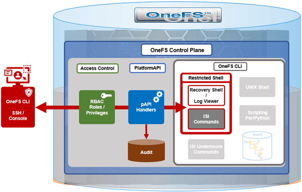
Written in Python, the restricted shell constrains users to a tight subset of the commands available in the regular OneFS command line shells, plus a couple of additional utilities. These include:
| CLI utility | Description |
|---|---|
ISI commands | The isi or “isi space” commands. These include the commands such as isi status, and so on. For the full set of isi commands, run isi –help. |
Shell commands | The supported shell commands include clear, exit, logout, and CTRL+D. |
Log access | The isi_log_access tool can be used if the user possesses the ISI_PRIV_SYS_SUPPORT privilege. |
Recovery shell | The recovery shell isi_recovery_shell can be used if the user possesses the ISI_PRIV_RECOVERY_SHELL and the security setting Restricted shell Enabled is configured to true. |
For a OneFS CLI command to be audited, its handler needs to call through the platform API (pAPI). This occurs with the regular isi commands but not necessarily with the “isi underscore” commands such as isi_for_array, and so on. While some of these isi_* commands write to log files, there is no uniform or consistent auditing or logging.
On the data access side, /ifs file system auditing works through the various OneFS protocol heads (NFS, SMB, S3, and so on). So if the CLI is used with an unrestricted shell to directly access and modify /ifs, any access and changes are unrecorded and unaudited.
In OneFS 9.5, the new restricted shell is included in the permitted shells list (/etc/shells):
# grep -i restr /etc/shells
/usr/local/restricted_shell/bin/restricted_shell.py
It can be easily set for a user through the CLI. For example, to configure the admin account to use the restricted shell, instead of its default of ZSH:
# isi auth users view admin | grep -i shell
                   Shell: /usr/local/bin/zsh
# isi auth users modify admin --shell=/usr/local/restricted_shell/bin/restricted_shell.py
# isi auth users view admin | grep -i shell
                   Shell: /usr/local/restricted_shell/bin/restricted_shell.py
OneFS can also be configured to limit non-root users to just the secure shell:
  Restricted shell Enabled: No
# isi security settings modify --restricted-shell-enabled=true
# isi security settings view | grep -i restr
  Restricted shell Enabled: Yes
The underlying configuration changes to support this include only allowing non-root users with approved shells in /etc/shells to log in through the console or SSH and having just /usr/local/restricted_shell/bin/restricted_shell.py in the /etc/shells config file.
Note that no users’ shells are changed when the configuration commands above are enacted. If users are intended to have shell access, their login shell must be changed before they can log in. Users will also require the privileges ISI_PRIV_LOGIN_SSH and/or ISI_PRIV_LOGIN_CONSOLE to be able to log in through SSH and the console, respectively.
While the WebUI in OneFS 9.5 does not provide a secure shell configuration page, the restricted shell can be enabled from the platform API, in addition to the CLI. The pAPI security settings now include a restricted_shell_enabled key, which can be enabled by setting to value=1, from its default of 0.
Be aware that, upon configuring a OneFS 9.5 cluster to run in hardened mode with the STIG profile (that is, isi hardening enable STIG), the restricted-shell-enable security setting is automatically set to true. This means that only root and users with ISI_PRIV_LOGIN_SSH and/or ISI_PRIV_LOGIN_CONSOLE privileges and the restricted shell as their shell will be permitted to log in to the cluster. We will focus on OneFS security hardening in a future article.
So let’s take a look at some examples of the restricted shell’s configuration and operation.
First, we log in as the admin user and modify the file and local auth provider password hash types to the more secure SHA512 from their default value of NTHash:
# ssh 10.244.34.34 -l admin
# isi auth file view System | grep -i hash
     Password Hash Type: NTHash
# isi auth local view System | grep -i hash
      Password Hash Type: NTHash
# isi auth file modify System –-password-hash-type=SHA512
# isi auth local modify System –-password-hash-type=SHA512
Note that a cluster’s default user admin uses role-based access control (RBAC), whereas root does not. As such, the root account should ideally be used as infrequently as possible and, ideally, considered solely as the account of last resort.
Next, the admin and root passwords are changed to generate new passwords using the SHA512 hash:
# isi auth users change-password root
# isi auth users change-password admin
An rl_ssh role is created and the SSH access privilege is added to it:
# isi auth roles create rl_ssh
# isi auth roles modify rl_ssh –-add-priv=ISI_PRIV_LOGIN_SSH
Then a regular user (usr_ssh_restricted) and an admin user (usr_admin_resticted) are created with restricted shell privileges:
# isi auth users create usr_ssh_restricted –-shell=/usr/local/restricted_shell/bin/restricted_shell.py –-set-password
# isi auth users create usr_admin_restricted –shell=/usr/local/restricted_shell/bin/restricted_shell.py –-set-password
We then assign roles to the new users. For the restricted SSH user, we add to our newly created rl_ssh role:
# isi auth roles modify rl_ssh –-add-user=usr_ssh_restricted
The admin user is then added to the security admin and the system admin roles:
# isi auth roles modify SecurityAdmin –-add-user=usr_admin_restricted
# isi auth roles modify SystemAdmin –-add-user=usr_admin_restricted
Next, we connect to the cluster through SSH and authenticate as the usr_ssh_restricted user:
$ ssh usr_ssh_restricted@10.246.178.121
 (usr_ssh_restricted@10.246.178.121) Password:
 Copyright (c) 2001-2023 Dell Inc. or its subsidiaries. All Rights Reserved.
 Copyright (c) 1992-2018 The FreeBSD Project.
 Copyright (c) 1979, 1980, 1983, 1986, 1988, 1989, 1991, 1992, 1993, 1994
         The Regents of the University of California. All rights reserved.
 PowerScale OneFS 9.5.0.0
Allowed commands are
         clear ...
         isi ...
         isi_recovery_shell ...
         isi_log_access ...
         exit
         logout
%
This account has no cluster RBAC privileges beyond SSH access so cannot run the various isi commands. For example, attempting to run isi status returns no data and, instead, warns of the need for event, job engine, and statistics privileges:
% isi status
Cluster Name: h7001
 __
 *** Capacity and health information require ***
 ***   the privilege: ISI_PRIV_STATISTICS.   ***
Critical Events:
*** Requires the privilege: ISI_PRIV_EVENT. ***
Cluster Job Status:
 __
*** Requires the privilege: ISI_PRIV_JOB_ENGINE. ***
Allowed commands are
         clear ...
         isi ...
         isi_recovery_shell ...
         isi_log_access ...
         exit
         logout
%
Similarly, standard UNIX shell commands, such as pwd and whoami, are also prohibited:
% pwd
Allowed commands are
        clear ...
        isi ...
        isi_recovery_shell ...
        isi_log_access ...
        exit
        logout
% whoami
Allowed commands are
        clear ...
        isi ...
        isi_recovery_shell ...
        isi_log_access ...
        exit
        logout
Indeed, without additional OneFS RBAC privileges, the only commands the usr_ssh_restricted user can actually run in the restricted shell are clear, exit, and logout:
Note that the restricted shell automatically logs out an inactive session after a short period of inactivity.
Next, we log in in with the usr_admin_restricted account:
$ ssh usr_admin_restricted@10.246.178.121
(usr_admin_restricted@10.246.178.121) Password:
Copyright (c) 2001-2023 Dell Inc. or its subsidiaries. All Rights Reserved.
Copyright (c) 1992-2018 The FreeBSD Project.
Copyright (c) 1979, 1980, 1983, 1986, 1988, 1989, 1991, 1992, 1993, 1994
        The Regents of the University of California. All rights reserved.
PowerScale OneFS 9.5.0.0
Allowed commands are
         clear ...
         isi ...
         isi_recovery_shell ...
         isi_log_access ...
         exit
         logout
 %
The isi commands now work because the user has the SecurityAdmin and SystemAdmin roles and privileges:
% isi auth roles list
Name
---------------
AuditAdmin
BackupAdmin
BasicUserRole
SecurityAdmin
StatisticsAdmin
SystemAdmin
VMwareAdmin
rl_console
rl_ssh
---------------
Total: 9
Allowed commands are
        clear ...
        isi ...
        isi_recovery_shell ...
        isi_log_access ...
        exit
        logout
% isi auth users view usr_admin_restricted
                    Name: usr_admin_restricted
                      DN: CN=usr_admin_restricted,CN=Users,DC=H7001
              DNS Domain: -
                  Domain: H7001
                Provider: lsa-local-provider:System
        Sam Account Name: usr_admin_restricted
                     UID: 2003
                     SID: S-1-5-21-3745626141-289409179-1286507423-1003
                 Enabled: Yes
                 Expired: No
                   Expiry: -
                  Locked: No
                   Email: -
                   GECOS: -
           Generated GID: No
           Generated UID: No
           Generated UPN: Yes
           Primary Group
                          ID: GID:1800
                        Name: Isilon Users
          Home Directory: /ifs/home/usr_admin_restricted
        Max Password Age: 4W
        Password Expired: No
         Password Expiry: 2023-05-30T17:16:53
       Password Last Set: 2023-05-02T17:16:53
        Password Expires: Yes
              Last Logon: -
                   Shell: /usr/local/restricted_shell/bin/restricted_shell.py
                     UPN: usr_admin_restricted@H7001
User Can Change Password: Yes
   Disable When Inactive: No
Allowed commands are
        clear ...
        isi ...
        isi_recovery_shell ...
        isi_log_access ...
        exit
        logout
%
However, the OneFS “isi underscore” commands are not supported under the restricted shell. For example, attempting to use the isi_for_array command:
% isi_for_array -s uname -a
Allowed commands are
        clear ...
        isi ...
        isi_recovery_shell ...
        isi_log_access ...
        exit
        logout
Note that, by default, the SecurityAdmin and SystemAdmin roles do not grant the usr_admin_restricted user the privileges needed to run the new isi_log_access and isi_recovery_shell commands.
In the next article in this series, we’ll take a look at these associated isi_log_access and isi_recovery_shell utilities that are also introduced in OneFS 9.5.
Author: Nick Trimbee

OneFS Firewall Management and Troubleshooting
Thu, 25 May 2023 14:41:59 -0000
|Read Time: 0 minutes
In the final blog in this series, we’ll focus on step five of the OneFS firewall provisioning process and turn our attention to some of the management and monitoring considerations and troubleshooting tools associated with the firewall.
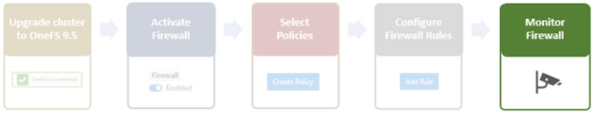
One can manage and monitor the firewall in OneFS 9.5 using the CLI, platform API, or WebUI. Because data security threats come from inside an environment as well as out, such as from a rogue IT employee, a good practice is to constrain the use of all-powerful ‘root’, ‘administrator’, and ‘sudo’ accounts as much as possible. Instead of granting cluster admins full rights, a preferred approach is to use OneFS’ comprehensive authentication, authorization, and accounting framework.
OneFS role-based access control (RBAC) can be used to explicitly limit who has access to configure and monitor the firewall. A cluster security administrator selects the desired access zone, creates a zone-aware role within it, assigns privileges, and then assigns members. For example, from the WebUI under Access > Membership and roles > Roles:
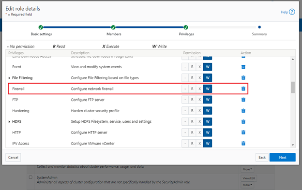
When these members login to the cluster from a configuration interface (WebUI, Platform API, or CLI) they inherit their assigned privileges.
Accessing the firewall from the WebUI and CLI in OneFS 9.5 requires the new ISI_PRIV_FIREWALL administration privilege.
# isi auth privileges -v | grep -i -A 2 firewall
         ID: ISI_PRIV_FIREWALL
Description: Configure network firewall
       Name: Firewall
   Category: Configuration
 Permission: w
This privilege can be assigned one of four permission levels for a role, including:
Permission Indicator | Description |
– | No permission. |
R | Read-only permission. |
X | Execute permission. |
W | Write permission. |
By default, the built-in ‘SystemAdmin’ roles is granted write privileges to administer the firewall, while the built-in ‘AuditAdmin’ role has read permission to view the firewall configuration and logs.
With OneFS RBAC, an enhanced security approach for a site could be to create two additional roles on a cluster, each with an increasing realm of trust. For example:
1. An IT ops/helpdesk role with ‘read’ access to the snapshot attributes would permit monitoring and troubleshooting the firewall, but no changes:
RBAC Role | Firewall Privilege | Permission |
IT_Ops | ISI_PRIV_FIREWALL | Read |
For example:
# isi auth roles create IT_Ops
# isi auth roles modify IT_Ops --add-priv-read ISI_PRIV_FIREWALL
# isi auth roles view IT_Ops | grep -A2 -i firewall
             ID: ISI_PRIV_FIREWALL
      Permission: r
2. A Firewall Admin role would provide full firewall configuration and management rights:
RBAC Role | Firewall Privilege | Permission |
FirewallAdmin | ISI_PRIV_FIREWALL | Write |
For example:
# isi auth roles create FirewallAdmin
# isi auth roles modify FirewallAdmin –add-priv-write ISI_PRIV_FIREWALL
# isi auth roles view FirewallAdmin | grep -A2 -i firewall
ID: ISI_PRIV_FIREWALL
Permission: w
Note that when configuring OneFS RBAC, remember to remove the ‘ISI_PRIV_AUTH’ and ‘ISI_PRIV_ROLE’ privilege from all but the most trusted administrators.
Additionally, enterprise security management tools such as CyberArk can also be incorporated to manage authentication and access control holistically across an environment. These can be configured to change passwords on trusted accounts frequently (every hour or so), require multi-Level approvals prior to retrieving passwords, and track and audit password requests and trends.
OneFS firewall limits
When working with the OneFS firewall, there are some upper bounds to the configurable attributes to keep in mind. These include:
Name | Value | Description |
MAX_INTERFACES | 500 | Maximum number of L2 interfaces including Ethernet, VLAN, LAGG interfaces on a node. |
MAX _SUBNETS | 100 | Maximum number of subnets within a OneFS cluster |
MAX_POOLS | 100 | Maximum number of network pools within a OneFS cluster |
DEFAULT_MAX_RULES | 100 | Default value of maximum rules within a firewall policy |
MAX_RULES | 200 | Upper limit of maximum rules within a firewall policy |
MAX_ACTIVE_RULES | 5000 | Upper limit of total active rules across the whole cluster |
MAX_INACTIVE_POLICIES | 200 | Maximum number of policies that are not applied to any network subnet or pool. They will not be written into ipfw tables. |
Firewall performance
Be aware that, while the OneFS firewall can greatly enhance the network security of a cluster, by nature of its packet inspection and filtering activity, it does come with a slight performance penalty (generally less than 5%).
Firewall and hardening mode
If OneFS STIG hardening (that is, from ‘isi hardening apply’) is applied to a cluster with the OneFS firewall disabled, the firewall will be automatically activated. On the other hand, if the firewall is already enabled, then there will be no change and it will remain active.
Firewall and user-configurable ports
Some OneFS services allow the TCP/UDP ports on which the daemon listens to be changed. These include:
Service | CLI Command | Default Port |
NDMP | isi ndmp settings global modify –port | 10000 |
S3 | isi s3 settings global modify –https-port | 9020, 9021 |
SSH | isi ssh settings modify –port | 22 |
The default ports for these services are already configured in the associated global policy rules. For example, for the S3 protocol:
# isi network firewall rules list | grep s3
default_pools_policy.rule_s3                  55     Firewall rule on s3 service                                                              allow
# isi network firewall rules view default_pools_policy.rule_s3
          ID: default_pools_policy.rule_s3
        Name: rule_s3
       Index: 55
 Description: Firewall rule on s3 service
    Protocol: TCP
   Dst Ports: 9020, 9021
Src Networks: -
   Src Ports: -
      Action: allow
Note that the global policies, or any custom policies, do not auto-update if these ports are reconfigured. This means that the firewall policies must be manually updated when changing ports. For example, if the NDMP port is changed from 10000 to 10001:
# isi ndmp settings global view
                       Service: False
                           Port: 10000
                            DMA: generic
          Bre Max Num Contexts: 64
MSB Context Retention Duration: 300
MSR Context Retention Duration: 600
        Stub File Open Timeout: 15
             Enable Redirector: False
              Enable Throttler: False
       Throttler CPU Threshold: 50
# isi ndmp settings global modify --port 10001
# isi ndmp settings global view | grep -i port
                           Port: 10001
The firewall’s NDMP rule port configuration must also be reset to 10001:
# isi network firewall rule list | grep ndmp
default_pools_policy.rule_ndmp                44     Firewall rule on ndmp service                                                            allow
# isi network firewall rule modify default_pools_policy.rule_ndmp --dst-ports 10001 --live
# isi network firewall rule view default_pools_policy.rule_ndmp | grep -i dst
   Dst Ports: 10001
Note that the –live flag is specified to enact this port change immediately.
Firewall and source-based routing
Under the hood, OneFS source-based routing (SBR) and the OneFS firewall both leverage ‘ipfw’. As such, SBR and the firewall share the single ipfw table in the kernel. However, the two features use separate ipfw table partitions.
This allows SBR and the firewall to be activated independently of each other. For example, even if the firewall is disabled, SBR can still be enabled and any configured SBR rules displayed as expected (that is, using ipfw set 0 show).
Firewall and IPv6
Note that the firewall’s global default policies have a rule allowing ICMP6 by default. For IPv6 enabled networks, ICMP6 is critical for the functioning of NDP (Neighbor Discovery Protocol). As such, when creating custom firewall policies and rules for IPv6-enabled network subnets/pools, be sure to add a rule allowing ICMP6 to support NDP. As discussed in a previous blog, an alternative (and potentially easier) approach is to clone a global policy to a new one and just customize its ruleset instead.
Firewall and FTP
The OneFS FTP service can work in two modes: Active and Passive. Passive mode is the default, where FTP data connections are created on top of random ephemeral ports. However, because the OneFS firewall requires fixed ports to operate, it only supports the FTP service in Active mode. Attempts to enable the firewall with FTP running in Passive mode will generate the following warning:
# isi ftp settings view | grep -i active
          Active Mode: No
# isi network firewall settings modify --enabled yes
FTP service is running in Passive mode. Enabling network firewall will lead to FTP clients having their connections blocked. To avoid this, please enable FTP active mode and ensure clients are configured in active mode before retrying. Are you sure you want to proceed and enable network firewall? (yes/[no]):
To activate the OneFS firewall in conjunction with the FTP service, first ensure that the FTP service is running in Active mode before enabling the firewall. For example:
# isi ftp settings view | grep -i enable
  FTP Service Enabled: Yes
# isi ftp settings view | grep -i active
          Active Mode: No
# isi ftp setting modify –active-mode true
# isi ftp settings view | grep -i active
          Active Mode: Yes
# isi network firewall settings modify --enabled yes
Note: Verify FTP active mode support and/or firewall settings on the client side, too.
Firewall monitoring and troubleshooting
When it comes to monitoring the OneFS firewall, the following logfiles and utilities provide a variety of information and are a good source to start investigating an issue:
Utility | Description |
/var/log/isi_firewall_d.log | Main OneFS firewall log file, which includes information from firewall daemon. |
/var/log/isi_papi_d.log | Logfile for platform AP, including Firewall related handlers. |
isi_gconfig -t firewall | CLI command that displays all firewall configuration info. |
ipfw show | CLI command that displays the ipfw table residing in the FreeBSD kernel. |
Note that the preceding files and command output are automatically included in logsets generated by the ‘isi_gather_info’ data collection tool.
You can run the isi_gconfig command with the ‘-q’ flag to identify any values that are not at their default settings. For example, the stock (default) isi_firewall_d gconfig context will not report any configuration entries:
# isi_gconfig -q -t firewall
[root] {version:1}
The firewall can also be run in the foreground for additional active rule reporting and debug output. For example, first shut down the isi_firewall_d service:
# isi services -a isi_firewall_d disable
The service 'isi_firewall_d' has been disabled.
Next, start up the firewall with the ‘-f’ flag.
# isi_firewall_d -f
Acquiring kevents for flxconfig
Acquiring kevents for nodeinfo
Acquiring kevents for firewall config
Initialize the firewall library
Initialize the ipfw set
ipfw: Rule added by ipfw is for temporary use and will be auto flushed soon. Use isi firewall instead.
cmd:/sbin/ipfw set enable 0 normal termination, exit code:0
isi_firewall_d is now running
Loaded master FlexNet config (rev:312)
Update the local firewall with changed files: flx_config, Node info, Firewall config
Start to update the firewall rule...
flx_config version changed!                              latest_flx_config_revision: new:312, orig:0
node_info version changed!                               latest_node_info_revision: new:1, orig:0
firewall gconfig version changed!                                latest_fw_gconfig_revision: new:17, orig:0
Start to update the firewall rule for firewall configuration (gconfig)
Start to handle the firewall configure (gconfig)
Handle the firewall policy default_pools_policy
ipfw: Rule added by ipfw is for temporary use and will be auto flushed soon. Use isi firewall instead.
32043 allow tcp from any to any 10000 in
cmd:/sbin/ipfw add 32043 set 8 allow TCP from any  to any 10000 in  normal termination, exit code:0
ipfw: Rule added by ipfw is for temporary use and will be auto flushed soon. Use isi firewall instead.
32044 allow tcp from any to any 389,636 in
cmd:/sbin/ipfw add 32044 set 8 allow TCP from any  to any 389,636 in  normal termination, exit code:0
Snip...
If the OneFS firewall is enabled and some network traffic is blocked, either this or the ipfw show CLI command will often provide the first clues.
Please note that the ipfw command should NEVER be used to modify the OneFS firewall table!
For example, say a rule is added to the default pools policy denying traffic on port 9876 from all source networks (0.0.0.0/0):
# isi network firewall rules create default_pools_policy.rule_9876 --index=100 --dst-ports 9876 --src-networks 0.0.0.0/0 --action deny –live
# isi network firewall rules view default_pools_policy.rule_9876
          ID: default_pools_policy.rule_9876
        Name: rule_9876
       Index: 100
 Description:
    Protocol: ALL
   Dst Ports: 9876
Src Networks: 0.0.0.0/0
   Src Ports: -
      Action: deny
Running ipfw show and grepping for the port will show this new rule:
# ipfw show | grep 9876
32099            0               0 deny ip from any to any 9876 in
The ipfw show command output also reports the statistics of how many IP packets have matched each rule This can be incredibly useful when investigating firewall issues. For example, a telnet session is initiated to the cluster on port 9876 from a client:
# telnet 10.224.127.8 9876
Trying 10.224.127.8...
telnet: connect to address 10.224.127.8: Operation timed out
telnet: Unable to connect to remote host
The connection attempt will time out because the port 9876 ‘deny’ rule will silently drop the packets. At the same time, the ipfw show command will increment its counter to report on the denied packets. For example:
# ipfw show | grep 9876
32099            9             540 deny ip from any to any 9876 in
If this behavior is not anticipated or desired, you can find the rule name by searching the rules list for the port number, in this case port 9876:
# isi network firewall rules list | grep 9876
default_pools_policy.rule_9876                100                                                                 deny
The offending rule can then be reverted to ‘allow’ traffic on port 9876:
# isi network firewall rules modify default_pools_policy.rule_9876 --action allow --live
Or easily deleted, if preferred:
# isi network firewall rules delete default_pools_policy.rule_9876 --live
Are you sure you want to delete firewall rule default_pools_policy.rule_9876? (yes/[no]): yes
Author: Nick Trimbee

Running PowerScale OneFS in Cloud - APEX File Storage for AWS
Wed, 28 Feb 2024 20:58:19 -0000
|Read Time: 0 minutes
PowerScale OneFS 9.6 now brings a new offering in AWS cloud — APEX File Storage for AWS. APEX File Storage for AWS is a software-defined cloud file storage service that provides high-performance, flexible, secure, and scalable file storage for AWS environments. It is a fully customer managed service that is designed to meet the needs of enterprise-scale file workloads running on AWS.
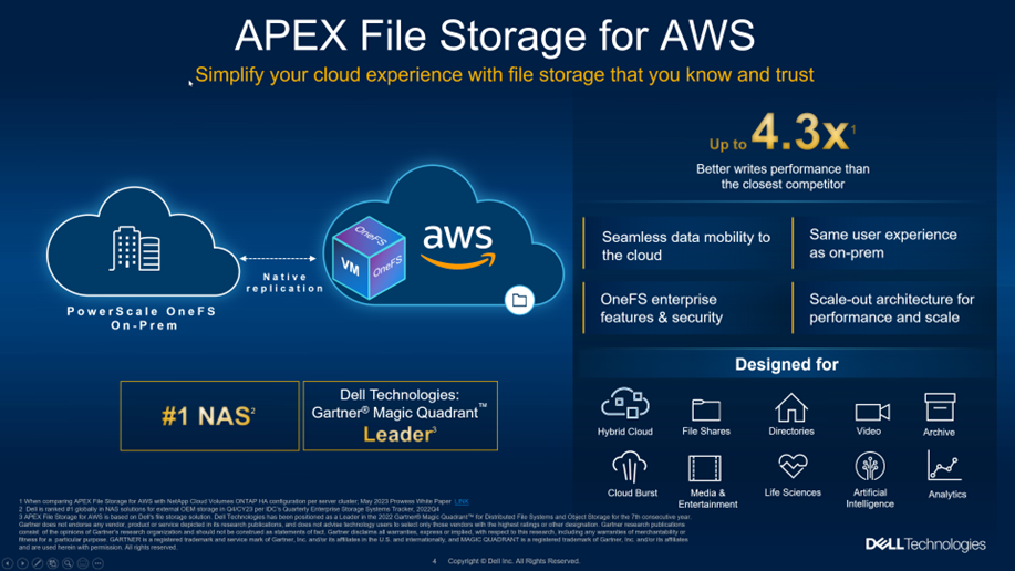
Benefits of running OneFS in Cloud
APEX File Storage for AWS brings the OneFS distributed file system software into the public cloud, allowing users to have the same management experience in the cloud as with their on-premises PowerScale appliance.
With APEX File Storage for AWS, you can easily deploy and manage file storage on AWS, without the need for hardware or software management. The service provides a scalable and elastic storage infrastructure that can grow or shrink, according to your actual business needs.
Some of the key features and benefits of APEX File Storage for AWS include:
- Scale-out: APEX File Storage for AWS is powered by the Dell PowerScale OneFS distributed file system. You can start with a small OneFS cluster and then expand it incrementally as your data storage requirements grow.
- Data management: APEX File Storage for AWS provides powerful data management capabilities, such as snapshot, data replication, and backup and restore. Because OneFS features are the same in the cloud as in on-premises, organizations can simplify operations and reduce management complexity with a consistent user experience.
- Simplified journey to hybrid cloud: More and more organizations operate in a hybrid cloud environment, where they need to move data between on-premises and cloud-based environments. APEX File Storage for AWS can help you bridge this gap by facilitating seamless data mobility between on-premises and the cloud with native replication and by providing a consistent data management platform across both environments. Once in the cloud, customers can take advantage of enterprise-class OneFS features such as multi-protocol support, CloudPools, data reduction, and snapshots, to run their workloads in the same way as they do on-premises. APEX File Storage for AWS can use CloudPools to tier cold or infrequently accessed data to lower cost cloud storage, such as AWS S3 object storage. CloudPools extends the OneFS namespace to the private/public cloud and allows you to store much more data than the usable cluster capacity.
- High performance: APEX File Storage for AWS delivers high-performance file storage with low-latency access to data, ensuring that you can access data quickly and efficiently.
Architecture
The architecture of APEX File Storage for AWS is based on the OneFS distributed file system, which consists of multiple cluster nodes to provide a single global namespace. Each cluster node is an instance of OneFS software that runs on an AWS EC2 instance and provides storage capacity and compute resources. The following diagram shows the architecture of APEX File Storage for AWS.
- Availability zone: APEX File Storage for AWS is designed to run in a single AWS availability zone to get the best performance.
- Virtual Private Cloud (VPC): APEX File Storage for AWS requires an AWS VPC to provide network connectivity.
- OneFS cluster internal subnet: The cluster nodes communicate with each other through the internal subnet. The internal subnet must be isolated from instances that are not in the cluster. Therefore, a dedicated subnet is required for the internal network interfaces of cluster nodes that do not share internal subnets with other EC2 instances.
- OneFS cluster external subnet: The cluster nodes communicate with clients through the external subnet by using different protocols, such as NFS, SMB, and S3.
- OneFS cluster internal network interfaces: Network interfaces that are located in the internal subnet.
- OneFS cluster external network interfaces: Network interfaces that are located in the external subnet.
- OneFS cluster internal security group: The security group applies to the cluster internal network interfaces and allows all traffic between the cluster nodes’ internal network interfaces only.
- OneFS cluster external security group: The security group applies to cluster external network interfaces and allows specific ingress traffic from clients.
- Elastic Compute Cloud (EC2) instance nodes: Cluster nodes that run the OneFS filesystem backed by Elastic Block Store (EBS) volumes and that provide network bandwidth.
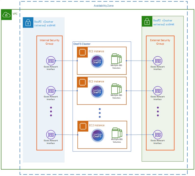
Supported cluster configuration
APEX File Storage for AWS provides two types of cluster configurations:
- Solid State Drive (SSD) cluster: APEX File Storage for AWS supports clusters backed by General Purpose SSD (gp3) EBS volumes with up to 1PiB cluster raw capacity. The gp3 EBS volumes are the latest generation of General Purpose SSD volumes, and the lowest cost SSD volume offered by AWS EBS. They balance price and performance for a wide variety of workloads.
Configuration items | Supported options |
Cluster size | 4 to 6 nodes |
EC2 instance type | All nodes in a cluster must be same instance size. The supported instance sizes are m5dn.8xlarge, m5dn.12xlarge, m5dn.16xlarge, or m5dn.24xlarge. See Amazon EC2 m5 instances for more details. |
EBS volume (disk) type | gp3 |
EBS volume (disk) counts per node | 5, 6, 10, 12, 15, 18, or 20 |
Single EBS volume sizes | 1TiB - 16TiB |
Cluster raw capacity | 24TiB - 1PiB |
Cluster protection level | +2n |
- Hard Disk Drive (HDD) cluster: APEX File Storage for AWS supports clusters backed by Throughput Optimized HDD (st1) EBS volumes with up to 360TiB cluster raw capacity. The st1 EBS volumes provide low-cost magnetic storage that defines performance in terms of throughput rather than IOPS. This volume type is a good fit for large sequential workloads.
Configuration items | Supported options |
Cluster size | 4 to 6 nodes |
EC2 instance type | All nodes in a cluster must be same instance size. The supported instance sizes are m5dn.8xlarge, m5dn.12xlarge, m5dn.16xlarge, or m5dn.24xlarge. See Amazon EC2 m5 instances for more details. |
EBS volume (disk) type | st1 |
EBS volume (disk) counts per node | 5 or 6 |
Single EBS volume sizes | 4TiB or 10TiB |
Cluster raw capacity | 80TiB - 360TiB |
Cluster protection level | +2n |
APEX File Storage for AWS can deliver 10GB/s seq read and 4GB/s seq write performance as the cluster size grows. To learn more details about APEX File Storage for AWS, see the following documentation.
Author: Lieven Lin

OneFS Firewall Configuration–Part 2
Wed, 17 May 2023 19:13:33 -0000
|Read Time: 0 minutes
In the previous article in this OneFS firewall series, we reviewed the upgrade, activation, and policy selection components of the firewall provisioning process.
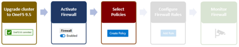
Now, we turn our attention to the firewall rule configuration step of the process.
As stated previously, role-based access control (RBAC) explicitly limits who has access to manage the OneFS firewall. So, ensure that the user account that will be used to enable and configure the OneFS firewall belongs to a role with the ‘ISI_PRIV_FIREWALL’ write privilege.
4. Configuring Firewall Rules
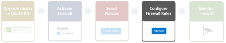
When the desired policy is created, the next step is to configure the rules. Clearly, the first step here is to decide which ports and services need securing or opening, beyond the defaults.
The following CLI syntax returns a list of all the firewall’s default services, plus their respective ports, protocols, and aliases, sorted by ascending port number:
# isi network firewall services list

Service Name     Port  Protocol   Aliases

---------------------------------------------

ftp-data         20    TCP        -

ftp              21    TCP        -

ssh              22    TCP        -

smtp             25    TCP        -

dns              53    TCP        domain

                       UDP

http             80    TCP        www

                                  www-http

kerberos         88    TCP        kerberos-sec

                       UDP

rpcbind          111   TCP        portmapper

                        UDP       sunrpc

                                 rpc.bind

ntp              123   UDP        -

dcerpc           135   TCP        epmap

                        UDP       loc-srv

netbios-ns       137   UDP        -

netbios-dgm      138   UDP        -

netbios-ssn      139   UDP        -

snmp             161   UDP        -

snmptrap         162   UDP        snmp-trap

mountd           300   TCP        nfsmountd

                       UDP

statd            302   TCP        nfsstatd

                       UDP

lockd            304   TCP       nfslockd

                       UDP

nfsrquotad       305   TCP        -

                       UDP

nfsmgmtd         306   TCP        -

                       UDP

ldap             389   TCP        -

                       UDP

https            443   TCP        -

smb              445   TCP        microsoft-ds

hdfs-datanode    585   TCP        -

asf-rmcp         623   TCP        -

                       UDP

ldaps            636   TCP        sldap

asf-secure-rmcp  664   TCP        -

                       UDP

ftps-data        989   TCP        -

ftps             990   TCP        -

nfs              2049  TCP        nfsd

                       UDP

tcp-2097         2097  TCP        -

tcp-2098         2098  TCP        -

tcp-3148         3148  TCP        -

tcp-3149         3149  TCP        -

tcp-3268         3268  TCP        -

tcp-3269         3269  TCP        -

tcp-5667         5667  TCP        -

tcp-5668         5668  TCP        -

isi_ph_rpcd      6557  TCP        -

isi_dm_d         7722  TCP        -

hdfs-namenode    8020  TCP        -

isi_webui        8080  TCP        apache2

webhdfs          8082  TCP        -

tcp-8083         8083  TCP        -

ambari-handshake 8440   TCP       -

ambari-heartbeat 8441   TCP       -

tcp-8443         8443  TCP        -

tcp-8470         8470  TCP        -

s3-http          9020  TCP        -

s3-https         9021  TCP        -

isi_esrs_d       9443  TCP        -

ndmp             10000 TCP       -

cee              12228 TCP       -

nfsrdma          20049 TCP       -

                       UDP

tcp-28080        28080 TCP       -

---------------------------------------------

Total: 55
Similarly, the following CLI command generates a list of existing rules and their associated policies, sorted in alphabetical order. For example, to show the first five rules:
# isi network firewall rules list –-limit 5

ID                                             Index  Description                                                                              Action

----------------------------------------------------------------------------------------------------------------------------------------------------

default_pools_policy.rule_ambari_handshake    41      Firewall rule on ambari-handshake service                                                allow

default_pools_policy.rule_ambari_heartbeat    42      Firewall rule on ambari-heartbeat service                                               allow

default_pools_policy.rule_catalog_search_req  50      Firewall rule on service for global catalog search requests                             allow

default_pools_policy.rule_cee                 52     Firewall rule on cee service                                                             allow

default_pools_policy.rule_dcerpc_tcp          18      Firewall rule on dcerpc(TCP) service                                                     allow

----------------------------------------------------------------------------------------------------------------------------------------------------

Total: 5
Both the ‘isi network firewall rules list’ and the ‘isi network firewall services list’ commands also have a ‘-v’ verbose option, and can return their output in csv, list, table, or json formats with the ‘–flag’.
To view the detailed info for a given firewall rule, in this case the default SMB rule, use the following CLI syntax:
# isi network firewall rules view default_pools_policy.rule_smb

          ID: default_pools_policy.rule_smb

        Name: rule_smb

       Index: 3

 Description: Firewall rule on smb service

    Protocol: TCP

   Dst Ports: smb

Src Networks: -

   Src Ports: -

      Action: allow
Existing rules can be modified and new rules created and added into an existing firewall policy with the ‘isi network firewall rules create’ CLI syntax. Command options include:
Option | Description |
–action | Allow, which mean pass packets.
Deny, which means silently drop packets.
Reject which means reply with ICMP error code. |
id | Specifies the ID of the new rule to create. The rule must be added to an existing policy. The ID can be up to 32 alphanumeric characters long and can include underscores or hyphens, but cannot include spaces or other punctuation. Specify the rule ID in the following format:
<policy_name>.<rule_name>
The rule name must be unique in the policy. |
–index | The rule index in the pool. The valid value is between 1 and 99. The lower value has the higher priority. If not specified, automatically go to the next available index (before default rule 100). |
–live | The live option must only be used when a user issues a command to create/modify/delete a rule in an active policy. Such changes will take effect immediately on all network subnets and pools associated with this policy. Using the live option on a rule in an inactive policy will be rejected, and an error message will be returned. |
–protocol | Specify the protocol matched for the inbound packets. Available values are tcp, udp, icmp, and all. if not configured, the default protocol all will be used. |
–dst-ports | Specify the network ports/services provided in the storage system which is identified by destination port(s). The protocol specified by –protocol will be applied on these destination ports. |
–src-networks | Specify one or more IP addresses with corresponding netmasks that are to be allowed by this firewall policy. The correct format for this parameter is address/netmask, similar to “192.0.2.128/25”. Separate multiple address/netmask pairs with commas. Use the value 0.0.0.0/0 for “any”. |
–src-ports | Specify the network ports/services provided in the storage system which is identified by source port(s). The protocol specified by –protocol will be applied on these source ports. |
Note that, unlike for firewall policies, there is no provision for cloning individual rules.
The following CLI syntax can be used to create new firewall rules. For example, to add ‘allow’ rules for the HTTP and SSH protocols, plus a ‘deny’ rule for port TCP 9876, into firewall policy fw_test1:
# isi network firewall rules create  fw_test1.rule_http  --index 1 --dst-ports http --src-networks 10.20.30.0/24,20.30.40.0/24 --action allow
# isi network firewall rules create  fw_test1.rule_ssh  --index 2 --dst-ports ssh --src-networks 10.20.30.0/24,20.30.40.0/16 --action allow
# isi network firewall rules create fw_test1.rule_tcp_9876 --index 3 --protocol tcp --dst-ports 9876   --src-networks 10.20.30.0/24,20.30.40.0/24 -- action deny
When a new rule is created in a policy, if the index value is not specified, it will automatically inherit the next available number in the series (such as index=4 in this case).
# isi network firewall rules create fw_test1.rule_2049 --protocol udp -dst-ports 2049 --src-networks 30.1.0.0/16 -- action deny
For a more draconian approach, a ‘deny’ rule could be created using the match-everything ‘*’ wildcard for destination ports and a 0.0.0.0/0 network and mask, which would silently drop all traffic:
# isi network firewall rules create fw_test1.rule_1234 --index=100--dst-ports * --src-networks 0.0.0.0/0 --action deny
When modifying existing firewall rules, use the following CLI syntax, in this case to change the source network of an HTTP allow rule (index 1) in firewall policy fw_test1:
# isi network firewall rules modify fw_test1.rule_http --index 1 --protocol ip --dst-ports http --src-networks 10.1.0.0/16 -- action allow
Or to modify an SSH rule (index 2) in firewall policy fw_test1, changing the action from ‘allow’ to ‘deny’:
# isi network firewall rules modify fw_test1.rule_ssh --index 2 --protocol tcp --dst-ports ssh --src-networks 10.1.0.0/16,20.2.0.0/16 -- action deny
Also, to re-order the custom TCP 9876 rule form the earlier example from index 3 to index 7 in firewall policy fw_test1.
# isi network firewall rules modify fw_test1.rule_tcp_9876 --index 7
Note that all rules equal or behind index 7 will have their index values incremented by one.
When deleting a rule from a firewall policy, any rule reordering is handled automatically. If the policy has been applied to a network pool, the ‘–live’ option can be used to force the change to take effect immediately. For example, to delete the HTTP rule from the firewall policy ‘fw_test1’:
# isi network firewall policies delete fw_test1.rule_http --live
Firewall rules can also be created, modified, and deleted within a policy from the WebUI by navigating to Cluster management > Firewall Configuration > Firewall Policies. For example, to create a rule that permits SupportAssist and Secure Gateway traffic on the 10.219.0.0/16 network:
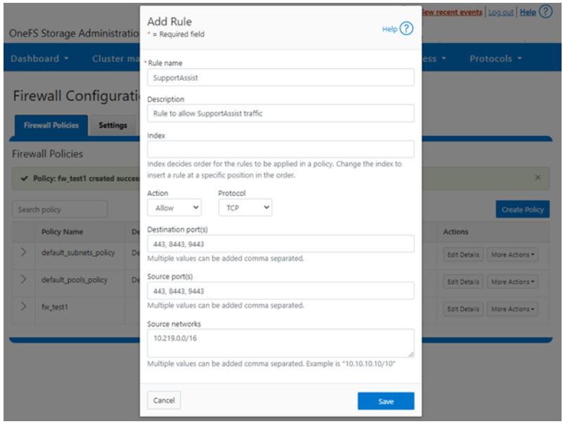
Once saved, the new rule is then displayed in the Firewall Configuration page:
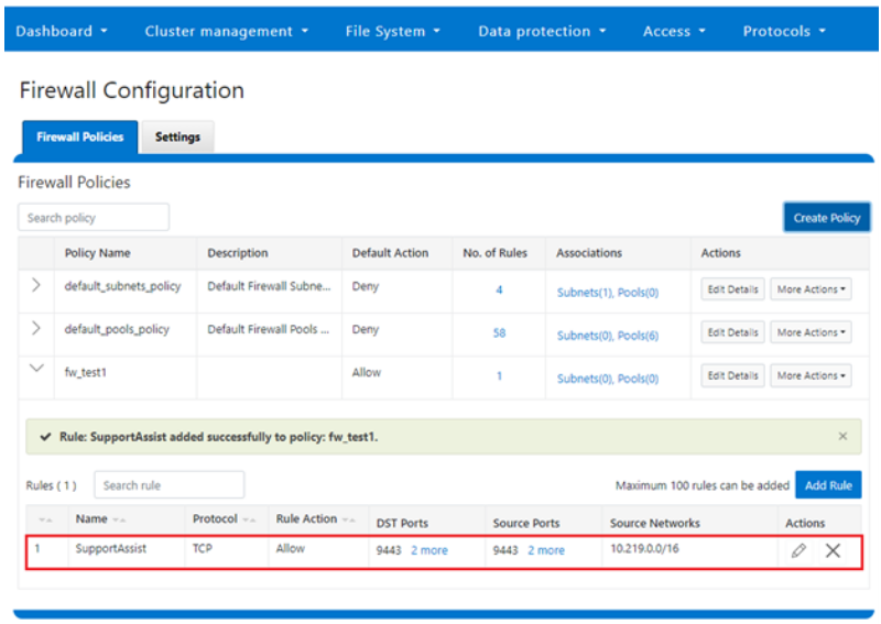
5. Firewall management and monitoring.
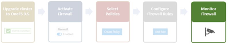
In the next and final article in this series, we’ll turn our attention to managing, monitoring, and troubleshooting the OneFS firewall (Step 5).
Author: Nick Trimbee

OneFS Firewall Configuration—Part 1
Tue, 02 May 2023 17:21:12 -0000
|Read Time: 0 minutes
The new firewall in OneFS 9.5 enhances the security of the cluster and helps prevent unauthorized access to the storage system. When enabled, the default firewall configuration allows remote systems access to a specific set of default services for data, management, and inter-cluster interfaces (network pools).
The basic OneFS firewall provisioning process is as follows:
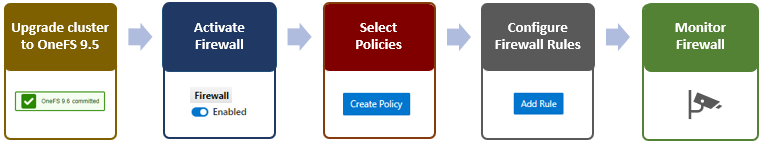
Note that role-based access control (RBAC) explicitly limits who has access to manage the OneFS firewall. In addition to the ubiquitous root, the cluster’s built-in SystemAdmin role has write privileges to configure and administer the firewall.
1. Upgrade cluster to OneFS 9.5.
First, to provision the firewall, the cluster must be running OneFS 9.5.
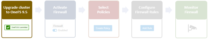
If you are upgrading from an earlier release, the OneFS 9.5 upgrade must be committed before enabling the firewall.
Also, be aware that configuration and management of the firewall in OneFS 9.5 requires the new ISI_PRIV_FIREWALL administration privilege.
# isi auth privilege | grep -i firewall
ISI_PRIV_FIREWALL                   Configure network firewall
This privilege can be granted to a role with either read-only or read/write permissions. By default, the built-in SystemAdmin role is granted write privileges to administer the firewall:
# isi auth roles view SystemAdmin | grep -A2 -i firewall
             ID: ISI_PRIV_FIREWALL
     Permission: w
Additionally, the built-in AuditAdmin role has read permission to view the firewall configuration and logs, and so on:
# isi auth roles view AuditAdmin | grep -A2 -i firewall
             ID: ISI_PRIV_FIREWALL
     Permission: r
Ensure that the user account that will be used to enable and configure the OneFS firewall belongs to a role with the ISI_PRIV_FIREWALL write privilege.
2. Activate firewall.
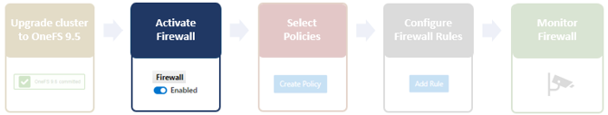
The OneFS firewall can be either enabled or disabled, with the latter as the default state.
The following CLI syntax will display the firewall’s global status (in this case disabled, the default):
# isi network firewall settings view
Enabled: False
Firewall activation can be easily performed from the CLI as follows:
# isi network firewall settings modify --enabled true
# isi network firewall settings view
Enabled: True
Or from the WebUI under Cluster management > Firewall Configuration > Settings:
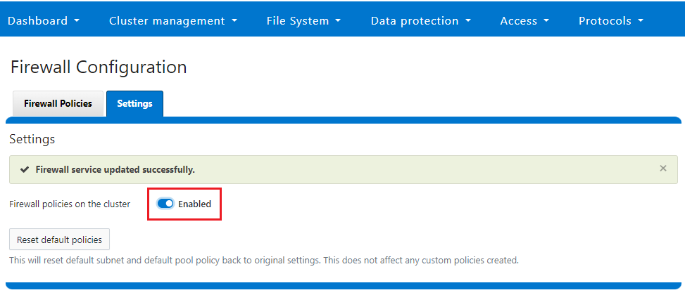
Note that the firewall is automatically enabled when STIG hardening is applied to a cluster.
3. Select policies.
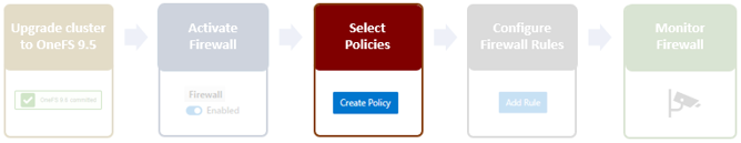
A cluster’s existing firewall policies can be easily viewed from the CLI with the following command:
# isi network firewall policies list
ID        Pools                    Subnets                   Rules
 -----------------------------------------------------------------------------
 fw_test1  groupnet0.subnet0.pool0  groupnet0.subnet1         test_rule1
 -----------------------------------------------------------------------------
 Total: 1
Or from the WebUI under Cluster management > Firewall Configuration > Firewall Policies:
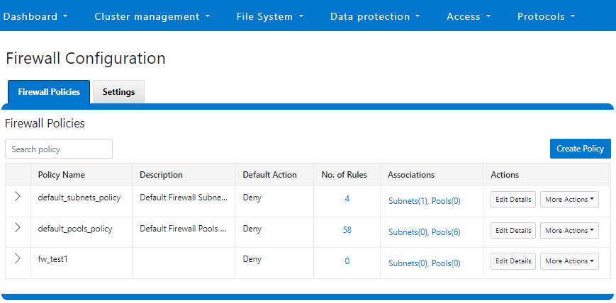
The OneFS firewall offers four main strategies when it comes to selecting a firewall policy:
- Retaining the default policy
- Reconfiguring the default policy
- Cloning the default policy and reconfiguring
- Creating a custom firewall policy
We’ll consider each of these strategies in order:
a. Retaining the default policy
In many cases, the default OneFS firewall policy value provides acceptable protection for a security-conscious organization. In these instances, once the OneFS firewall has been enabled on a cluster, no further configuration is required, and the cluster administrators can move on to the management and monitoring phase.
The firewall policy for all front-end cluster interfaces (network pool) is the default. While the default policy can be modified, be aware that this default policy is global. As such, any change against it will affect all network pools using this default policy.
The following table describes the default firewall policies that are assigned to each interface:
Policy | Description |
Default pools policy | Contains rules for the inbound default ports for TCP and UDP services in OneFS |
Default subnets policy | Contains rules for:
|
These can be viewed from the CLI as follows:
# isi network firewall policies view default_pools_policy
            ID: default_pools_policy
          Name: default_pools_policy
    Description: Default Firewall Pools Policy
Default Action: deny
      Max Rules: 100
          Pools: groupnet0.subnet0.pool0, groupnet0.subnet0.testpool1, groupnet0.subnet0.testpool2, groupnet0.subnet0.testpool3, groupnet0.subnet0.testpool4, groupnet0.subnet0.poolcava
        Subnets: -
          Rules: rule_ldap_tcp, rule_ldap_udp, rule_reserved_for_hw_tcp, rule_reserved_for_hw_udp, rule_isi_SyncIQ, rule_catalog_search_req, rule_lwswift, rule_session_transfer, rule_s3, rule_nfs_tcp, rule_nfs_udp, rule_smb, rule_hdfs_datanode, rule_nfsrdma_tcp, rule_nfsrdma_udp, rule_ftp_data, rule_ftps_data, rule_ftp, rule_ssh, rule_smtp, rule_http, rule_kerberos_tcp, rule_kerberos_udp, rule_rpcbind_tcp, rule_rpcbind_udp, rule_ntp, rule_dcerpc_tcp, rule_dcerpc_udp, rule_netbios_ns, rule_netbios_dgm, rule_netbios_ssn, rule_snmp, rule_snmptrap, rule_mountd_tcp, rule_mountd_udp, rule_statd_tcp, rule_statd_udp, rule_lockd_tcp, rule_lockd_udp, rule_nfsrquotad_tcp, rule_nfsrquotad_udp, rule_nfsmgmtd_tcp, rule_nfsmgmtd_udp, rule_https, rule_ldaps, rule_ftps, rule_hdfs_namenode, rule_isi_webui, rule_webhdfs, rule_ambari_handshake, rule_ambari_heartbeat, rule_isi_esrs_d, rule_ndmp, rule_isi_ph_rpcd, rule_cee, rule_icmp, rule_icmp6, rule_isi_dm_d
 # isi network firewall policies view default_subnets_policy
            ID: default_subnets_policy
          Name: default_subnets_policy
    Description: Default Firewall Subnets Policy
Default Action: deny
      Max Rules: 100
          Pools: -
        Subnets: groupnet0.subnet0
          Rules: rule_subnets_dns_tcp, rule_subnets_dns_udp, rule_icmp, rule_icmp6
Or from the WebUI under Cluster management > Firewall Configuration > Firewall Policies:
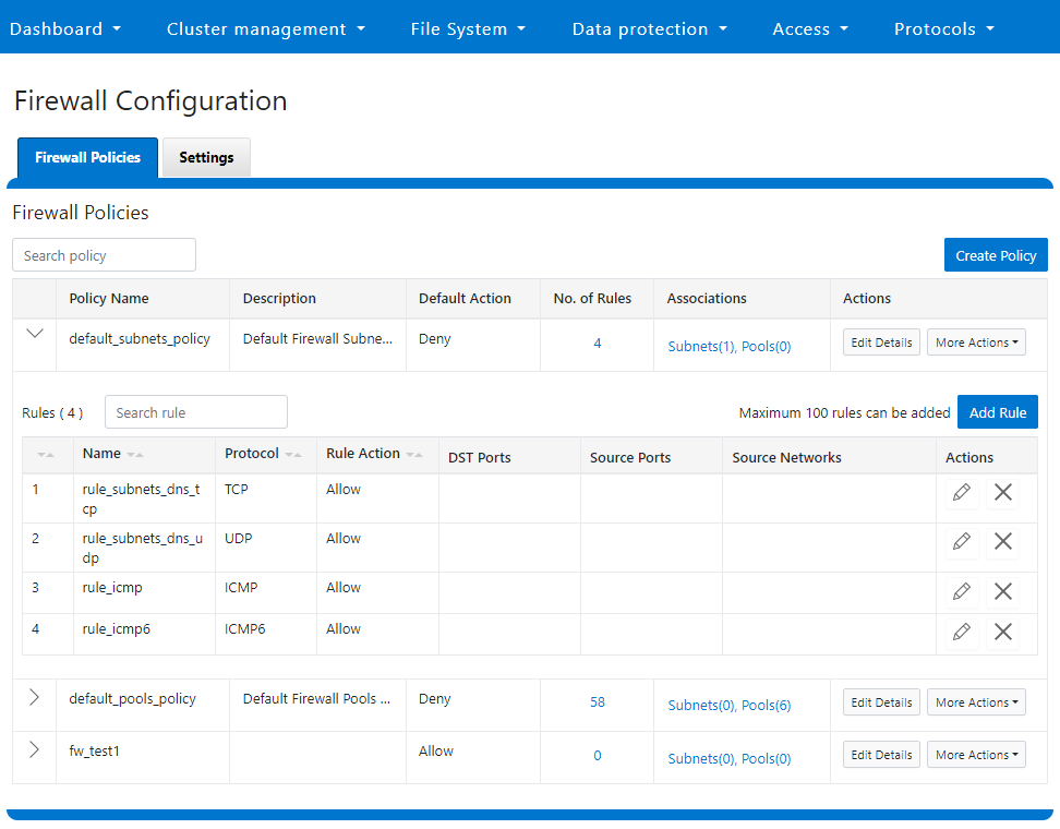
b. Reconfiguring the default policy
Depending on an organization’s threat levels or security mandates, there may be a need to restrict access to certain additional IP addresses and/or management service protocols.
If the default policy is deemed insufficient, reconfiguring the default firewall policy can be a good option if only a small number of rule changes are required. The specifics of creating, modifying, and deleting individual firewall rules is covered later in this article (step 3).
Note that if new rule changes behave unexpectedly, or firewall configuration generally goes awry, OneFS does provide a “get out of jail free” card. In a pinch, the global firewall policy can be quickly and easily restored to its default values. This can be achieved with the following CLI syntax:
# isi network firewall reset-global-policy
This command will reset the global firewall policies to the original system defaults. Are you sure you want to continue? (yes/[no]):
Alternatively, the default policy can also be easily reverted from the WebUI by clicking the Reset default policies:
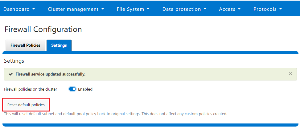
c. Cloning the default policy and reconfiguring
Another option is cloning, which can be useful when batch modification or a large number of changes to the current policy are required. By cloning the default firewall policy, an exact copy of the existing policy and its rules is generated, but with a new policy name. For example:
# isi network firewall policies clone default_pools_policy clone_default_pools_policy
# isi network firewall policies list | grep -i clone
clone_default_pools_policy -
Cloning can also be initiated from the WebUI under Firewall Configuration > Firewall Policies > More Actions > Clone Policy:
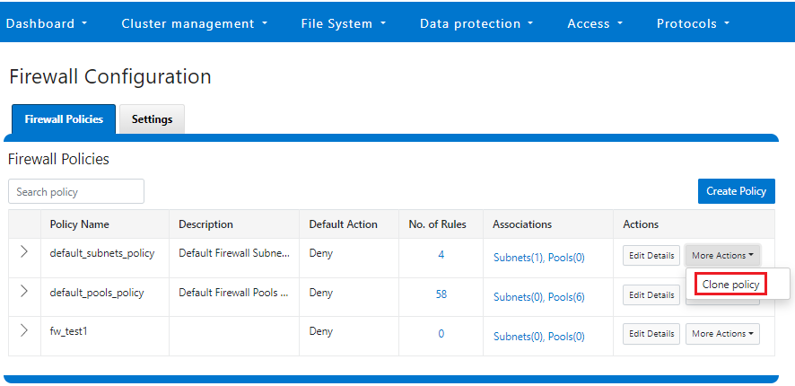
Enter a name for the clone in the Policy Name field in the pop-up window, and click Save:
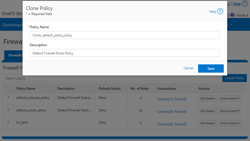
Once cloned, the policy can then be easily reconfigured to suit. For example, to modify the policy fw_test1 and change its default-action from deny-all to allow-all:
# isi network firewall policies modify fw_test1 --default-action allow-all
When modifying a firewall policy, you can use the --live CLI option to force it to take effect immediately. Note that the --live option is only valid when issuing a command to modify or delete an active custom policy and to modify default policy. Such changes will take effect immediately on all network subnets and pools associated with this policy. Using the --live option on an inactive policy will be rejected, and an error message returned.
Options for creating or modifying a firewall policy include:
Option | Description |
--default-action | Automatically add one rule to deny all or allow all to the bottom of the rule set for this created policy (Index = 100). |
--max-rule-num | By default, each policy when created could have a maximum of 100 rules (including one default rule), so user could configure a maximum of 99 rules. User could expand the maximum rule number to a specified value. Currently this value is limited to 200 (and user could configure a maximum of 199 rules). |
--add-subnets | Specify the network subnet(s) to add to policy, separated by a comma. |
--remove-subnets | Specify the networks subnets to remove from policy and fall back to global policy. |
--add-pools | Specify the network pool(s) to add to policy, separated by a comma. |
--remove-pools | Specify the networks pools to remove from policy and fall back to global policy. |
When you modify firewall policies, OneFS issues the following warning to verify the changes and help avoid the risk of a self-induced denial-of-service:
# isi network firewall policies modify --pools groupnet0.subnet0.pool0 fw_test1
Changing the Firewall Policy associated with a subnet or pool may change the networks and/or services allowed to connect to OneFS. Please confirm you have selected the correct Firewall Policy and Subnets/Pools. Are you sure you want to continue? (yes/[no]): yes
Once again, having the following CLI command handy, plus console access to the cluster is always a prudent move:
# isi network firewall reset-global-policy
So adding network pools or subnets to a firewall policy will cause the previous policy to be removed from them. Similarly, adding network pools or subnets to the global default policy will revert any custom policy configuration they might have. For example, to apply the firewall policy fw_test1 to IP Pool groupnet0.subnet0.pool0 and groupnet0.subnet0.pool1:
# isi network pools view groupnet0.subnet0.pool0 | grep -i firewall
       Firewall Policy: default_pools_policy
# isi network firewall policies modify fw_test1 --add-pools groupnet0.subnet0.pool0, groupnet0.subnet0.pool1
# isi network pools view groupnet0.subnet0.pool0 | grep -i firewall
       Firewall Policy: fw_test1
Or to apply the firewall policy fw_test1 to IP Pool groupnet0.subnet0.pool0 and groupnet0.subnet0:
# isi network firewall policies modify fw_test1 --apply-subnet groupnet0.subnet0.pool0, groupnet0.subnet0
# isi network pools view groupnet0.subnet0.pool0 | grep -i firewall
 Firewall Policy: fw_test1
# isi network subnets view groupnet0.subnet0 | grep -i firewall
 Firewall Policy: fw_test1
To reapply global policy at any time, either add the pools to the default policy:
# isi network firewall policies modify default_pools_policy --add-pools groupnet0.subnet0.pool0, groupnet0.subnet0.pool1
# isi network pools view groupnet0.subnet0.pool0 | grep -i firewall
 Firewall Policy: default_subnets_policy
# isi network subnets view groupnet0.subnet1 | grep -i firewall
 Firewall Policy: default_subnets_policy
Or remove the pool from the custom policy:
# isi network firewall policies modify fw_test1 --remove-pools groupnet0.subnet0.pool0 groupnet0.subnet0.pool1
You can also manage firewall policies on a network pool in the OneFS WebUI by going to Cluster configuration > Network configuration > External network > Edit pool details. For example:
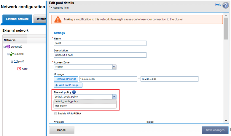
Be aware that cloning is also not limited to the default policy because clones can be made of any custom policies too. For example:
# isi network firewall policies clone clone_default_pools_policy fw_test1
d. Creating a custom firewall policy
Alternatively, a custom firewall policy can also be created from scratch. This can be accomplished from the CLI using the following syntax, in this case to create a firewall policy named fw_test1:
# isi network firewall policies create fw_test1 --default-action deny
# isi network firewall policies view fw_test1
            ID: fw_test1
          Name: fw_test1
    Description:
Default Action: deny
      Max Rules: 100
          Pools: -
        Subnets: -
          Rules: -
Note that if a default-action is not specified in the CLI command syntax, it will automatically default to deny.
Firewall policies can also be configured in the OneFS WebUI by going to Cluster management > Firewall Configuration > Firewall Policies > Create Policy:
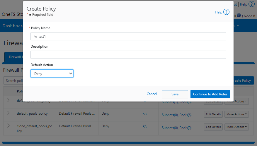
However, in contrast to the CLI, if a default-action is not specified when a policy is created in the WebUI, the automatic default is to Allow because the drop-down list works alphabetically.
If and when a firewall policy is no longer required, it can be swiftly and easily removed. For example, the following CLI syntax deletes the firewall policy fw_test1, clearing out any rules within this policy container:
# isi network firewall policies delete fw_test1
Are you sure you want to delete firewall policy fw_test1? (yes/[no]): yes
Note that the default global policies cannot be deleted.
# isi network firewall policies delete default_subnets_policy
Are you sure you want to delete firewall policy default_subnets_policy? (yes/[no]): yes
Firewall policy: Cannot delete default policy default_subnets_policy.
4. Configure firewall rules.
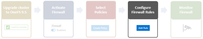
In the next article in this series, we’ll turn our attention to this step, configuring the OneFS firewall rules.

OneFS Host-Based Firewall
Wed, 26 Apr 2023 15:40:15 -0000
|Read Time: 0 minutes
Among the array of security features introduced in OneFS 9.5 is a new host-based firewall. This firewall allows cluster administrators to configure policies and rules on a PowerScale cluster in order to meet the network and application management needs and security mandates of an organization.
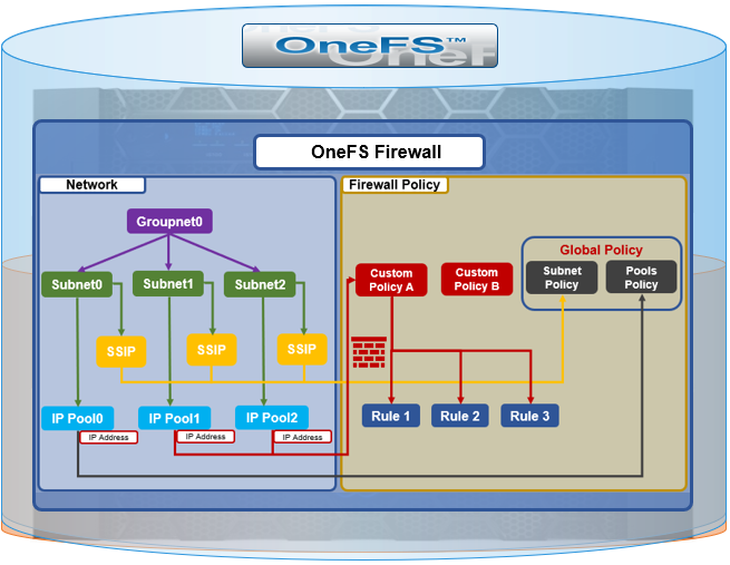
The OneFS firewall protects the cluster’s external, or front-end, network and operates as a packet filter for inbound traffic. It is available upon installation or upgrade to OneFS 9.5 but is disabled by default in both cases. However, the OneFS STIG hardening profile automatically enables the firewall and the default policies, in addition to manual activation.
The firewall generally manages IP packet filtering in accordance with the OneFS Security Configuration Guide, especially in regards to the network port usage. Packet control is governed by firewall policies, which have one or more individual rules.
Item | Description | Match | Action |
Firewall Policy | Each policy is a set of firewall rules. | Rules are matched by index in ascending order. | Each policy has a default action. |
Firewall Rule | Each rule specifies what kinds of network packets should be matched by Firewall engine and what action should be taken upon them. | Matching criteria includes protocol, source ports, destination ports, source network address). | Options are allow, deny, or reject. |
A security best practice is to enable the OneFS firewall using the default policies, with any adjustments as required. The recommended configuration process is as follows:
Step | Details |
1. Access | Ensure that the cluster uses a default SSH or HTTP port before enabling. The default firewall policies block all nondefault ports until you change the policies. |
2. Enable | Enable the OneFS firewall. |
3. Compare | Compare your cluster network port configurations against the default ports listed in Network port usage. |
4. Configure | Edit the default firewall policies to accommodate any non-standard ports in use in the cluster. NOTE: The firewall policies do not automatically update when port configurations are changed. |
5. Constrain | Limit access to the OneFS Web UI to specific administrator terminals. |
Under the hood, the OneFS firewall is built upon the ubiquitous ipfirewall, or ipfw, which is FreeBSD’s native stateful firewall, packet filter, and traffic accounting facility.
Firewall configuration and management is through the CLI, or platform API, or WebUI, and OneFS 9.5 introduces a new Firewall Configuration page to support this. Note that the firewall is only available once a cluster is already running OneFS 9.5 and the feature has been manually enabled, activating the isi_firewall_d service. The firewall’s configuration is split between gconfig, which handles the settings and policies, and the ipfw table, which stores the rules themselves.
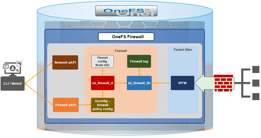
The firewall gracefully handles SmartConnect dynamic IP movement between nodes since firewall policies are applied per network pool. Additionally, being network pool based allows the firewall to support OneFS access zones and shared/multitenancy models.
The individual firewall rules, which are essentially simplified wrappers around ipfw rules, work by matching packets through the 5-tuples that uniquely identify an IPv4 UDP or TCP session:
- Source IP address
- Source port
- Destination IP address
- Destination port
- Transport protocol
The rules are then organized within a firewall policy, which can be applied to one or more network pools.
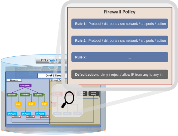
Note that each pool can only have a single firewall policy applied to it. If there is no custom firewall policy configured for a network pool, it automatically uses the global default firewall policy.
When enabled, the OneFS firewall function is cluster wide, and all inbound packets from external interfaces will go through either the custom policy or default global policy before reaching the protocol handling pathways. Packets passed to the firewall are compared against each of the rules in the policy, in rule-number order. Multiple rules with the same number are permitted, in which case they are processed in order of insertion. When a match is found, the action corresponding to that matching rule is performed. A packet is checked against the active ruleset in multiple places in the protocol stack, and the basic flow is as follows:
- Get the logical interface for incoming packets.
- Find all network pools assigned to this interface.
- Compare these network pools one by one with destination IP address to find the matching pool (either custom firewall policy, or default global policy).
- Compare each rule with service (protocol and destination ports) and source IP address in this pool in order of lowest index value. If matched, perform actions according to the associated rule.
- If no rule matches, go to the final rule (deny all or allow all), which is specified upon policy creation.
The OneFS firewall automatically reserves 20,000 rules in the ipfw table for its custom and default policies and rules. By default, each policy can have a maximum of 100 rules, including one default rule. This translates to an effective maximum of 99 user-defined rules per policy, because the default rule is reserved and cannot be modified. As such, a maximum of 198 policies can be applied to pools or subnets since the default-pools-policy and default-subnets-policy are reserved and cannot be deleted.
Additional firewall bounds and limits to keep in mind include:
Name | Value | Description |
MAX_INTERFACES | 500 | Maximum number of Layer 2 interfaces per node (including Ethernet, VLAN, LAGG interfaces). |
MAX _SUBNETS | 100 | Maximum number of subnets within a OneFS cluster. |
MAX_POOLS | 100 | Maximum number of network pools within a OneFS cluster. |
DEFAULT_MAX_RULES | 100 | Default value of maximum rules within a firewall policy. |
MAX_RULES | 200 | Upper limit of maximum rules within a firewall policy. |
MAX_ACTIVE_RULES | 5000 | Upper limit of total active rules across the whole cluster. |
MAX_INACTIVE_POLICIES | 200 | Maximum number of policies that are not applied to any network subnet or pool. They will not be written into ipfw table. |
The firewall default global policy is ready to use out of the box and, unless a custom policy has been explicitly configured, all network pools use this global policy. Custom policies can be configured by either cloning and modifying an existing policy or creating one from scratch.
Component | Description |
Custom policy | A user-defined container with a set of rules. A policy can be applied to multiple network pools, but a network pool can only apply one policy. |
Firewall rule | An ipfw-like rule that can be used to restrict remote access. Each rule has an index that is valid within the policy. Index values range from 1 to 99, with lower numbers having higher priority. Source networks are described by IP and netmask, and services can be expressed either by port number (i.e., 80) or service name (i.e., http, ssh, smb). The * wildcard can also be used to denote all services. Supported actions include allow, drop, and reject. |
Default policy | A global policy to manage all default services, used for maintaining OneFS minimum running and management. While Deny any is the default action of the policy, the defined service rules have a default action to allow all remote access. All packets not matching any of the rules are automatically dropped. Two default policies:
Note that these two default policies cannot be deleted, but individual rule modification is permitted in each. |
Default services | The firewall’s default predefined services include the usual suspects, such as: DNS, FTP, HDFS, HTTP, HTTPS, ICMP, NDMP, NFS, NTP, S3, SMB, SNMP, SSH, and so on. A full listing is available in the isi network firewall services list CLI command output. |
For a given network pool, either the global policy or a custom policy is assigned and takes effect. Additionally, all configuration changes to either policy type are managed by gconfig and are persistent across cluster reboots.
In the next article in this series we’ll take a look at the CLI and WebUI configuration and management of the OneFS firewall.

OneFS Snapshot Security
Fri, 21 Apr 2023 17:11:00 -0000
|Read Time: 0 minutes
In this era of elevated cyber-crime and data security threats, there is increasing demand for immutable, tamper-proof snapshots. Often this need arises as part of a broader security mandate, ideally proactively, but oftentimes as a response to a security incident. OneFS addresses this requirement in the following ways:
On-cluster | Off-cluster |
|
|
Read-only snapshots
At its core, OneFS SnapshotIQ generates read-only, point-in-time, space efficient copies of a defined subset of a cluster’s data.
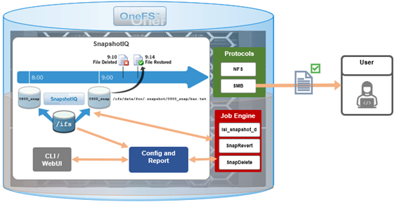
Only the changed blocks of a file are stored when updating OneFS snapshots, ensuring efficient storage utilization. They are also highly scalable and typically take less than a second to create, while generating little performance overhead. As such, the RPO (recovery point objective) and RTO (recovery time objective) of a OneFS snapshot can be very small and highly flexible, with the use of rich policies and schedules.
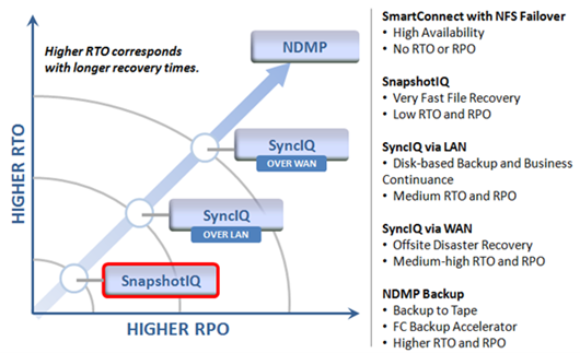
OneFS Snapshots are created manually, on a schedule, or automatically generated by OneFS to facilitate system operations. But whatever the generation method, when a snapshot has been taken, its contents cannot be manually altered.
Snapshot Locks
In addition to snapshot contents immutability, for an enhanced level of tamper-proofing, SnapshotIQ also provides the ability to lock snapshots with the ‘isi snapshot locks’ CLI syntax. This prevents snapshots from being accidentally or unintentionally deleted.
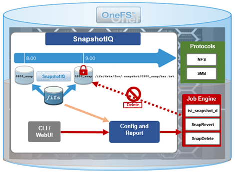
For example, a manual snapshot, ‘snaploc1’ is taken of /ifs/test:
# isi snapshot snapshots create /ifs/test --name snaploc1
# isi snapshot snapshots list | grep snaploc1
79188 snaploc1                                     /ifs/test
A lock is then placed on it (in this case lock ID=1):
# isi snapshot locks create snaplock1
# isi snapshot locks list snaploc1
ID
----
1
----
Total: 1
Attempts to delete the snapshot fail because the lock prevents its removal:
# isi snapshot snapshots delete snaploc1
Are you sure? (yes/[no]): yes
Snapshot "snaploc1" can't be deleted because it is locked
The CLI command ‘isi snapshot locks delete <lock_ID>’ can be used to clear existing snapshot locks, if desired. For example, to remove the only lock (ID=1) from snapshot ‘snaploc1’:
# isi snapshot locks list snaploc1
ID
----
1
----
Total: 1
# isi snapshot locks delete snaploc1 1
Are you sure you want to delete snapshot lock 1 from snaploc1? (yes/[no]): yes
# isi snap locks view snaploc1 1
No such lock
When the lock is removed, the snapshot can then be deleted:
# isi snapshot snapshots delete snaploc1
Are you sure? (yes/[no]): yes
# isi snapshot snapshots list| grep -i snaploc1 | wc -l
       0
Note that a snapshot can have up to a maximum of sixteen locks on it at any time. Also, lock numbers are continually incremented and not recycled upon deletion.
Like snapshot expiration, snapshot locks can also have an expiration time configured. For example, to set a lock on snapshot ‘snaploc1’ that expires at 1am on April 1st, 2024:
# isi snap lock create snaploc1 --expires '2024-04-01T01:00:00'
# isi snap lock list snaploc1
ID
----
36
----
Total: 1
# isi snap lock view snaploc1 33
     ID: 36
Comment:
Expires: 2024-04-01T01:00:00
  Count: 1
Note that if the duration period of a particular snapshot lock expires but others remain, OneFS will not delete that snapshot until all the locks on it have been deleted or expired.
The following table provides an example snapshot expiration schedule, with monthly locked snapshots to prevent deletion:
Snapshot Frequency | Snapshot Time | Snapshot Expiration | Max Retained Snapshots |
Every other hour | Start at 12:00AM End at 11:59AM | 1 day | 27 |
Every day | At 12:00AM | 1 week | |
Every week | Saturday at 12:00AM | 1 month | |
Every month | First Saturday of month at 12:00AM | Locked |
Roles-based Access Control
Read-only snapshots plus locks present physically secure snapshots on a cluster. However, if you can login to the cluster and have the required elevated administrator privileges to do so, you can still remove locks and/or delete snapshots.
Because data security threats come from inside an environment as well as out, such as from a disgruntled IT employee or other internal bad actor, another key to a robust security profile is to constrain the use of all-powerful ‘root’, ‘administrator’, and ‘sudo’ accounts as much as possible. Instead, of granting cluster admins full rights, a preferred security best practice is to leverage the comprehensive authentication, authorization, and accounting framework that OneFS natively provides.
OneFS role-based access control (RBAC) can be used to explicitly limit who has access to manage and delete snapshots. This granular control allows you to craft administrative roles that can create and manage snapshot schedules, but prevent their unlocking and/or deletion. Similarly, lock removal and snapshot deletion can be isolated to a specific security role (or to root only).
A cluster security administrator selects the desired access zone, creates a zone-aware role within it, assigns privileges, and then assigns members.

For example, from the WebUI under Access > Membership and roles > Roles:
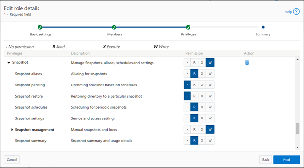
When these members access the cluster through the WebUI, PlatformAPI, or CLI, they inherit their assigned privileges.
The specific privileges that can be used to segment OneFS snapshot management include:
Privilege | Description |
ISI_PRIV_SNAPSHOT_ALIAS | Aliasing for snapshots |
ISI_PRIV_SNAPSHOT_LOCKS | Locking of snapshots from deletion |
ISI_PRIV_SNAPSHOT_PENDING | Upcoming snapshot based on schedules |
ISI_PRIV_SNAPSHOT_RESTORE | Restoring directory to a particular snapshot |
ISI_PRIV_SNAPSHOT_SCHEDULES | Scheduling for periodic snapshots |
ISI_PRIV_SNAPSHOT_SETTING | Service and access settings |
ISI_PRIV_SNAPSHOT_SNAPSHOTMANAGEMENT | Manual snapshots and locks |
ISI_PRIV_SNAPSHOT_SNAPSHOT_SUMMARY | Snapshot summary and usage details |
Each privilege can be assigned one of four permission levels for a role, including:
Permission Indicator | Description |
– | No permission |
R | Read-only permission |
X | Execute permission |
W | Write permission |
The ability for a user to delete a snapshot is governed by the ‘ISI_PRIV_SNAPSHOT_SNAPSHOTMANAGEMENT’ privilege. Similarly, the ‘ISI_PRIV_SNAPSHOT_LOCKS’ privilege governs lock creation and removal.
In the following example, the ‘snap’ role has ‘read’ rights for the ‘ISI_PRIV_SNAPSHOT_LOCKS’ privilege, allowing a user associated with this role to view snapshot locks:
# isi auth roles view snap | grep -I -A 1 locks
             ID: ISI_PRIV_SNAPSHOT_LOCKS
     Permission: r
--
# isi snapshot locks list snaploc1
ID
----
1
----
Total: 1
However, attempts to remove the lock ‘ID 1’ from the ‘snaploc1’ snapshot fail without write privileges:
# isi snapshot locks delete snaploc1 1
Privilege check failed. The following write privilege is required: Snapshot locks (ISI_PRIV_SNAPSHOT_LOCKS)
Write privileges are added to ‘ISI_PRIV_SNAPSHOT_LOCKS’ in the ‘’snaploc1’ role:
# isi auth roles modify snap –-add-priv-write ISI_PRIV_SNAPSHOT_LOCKS
# isi auth roles view snap | grep -I -A 1 locks
             ID: ISI_PRIV_SNAPSHOT_LOCKS
     Permission: w
--
This allows the lock ‘ID 1’ to be successfully deleted from the ‘snaploc1’ snapshot:
# isi snapshot locks delete snaploc1 1
Are you sure you want to delete snapshot lock 1 from snaploc1? (yes/[no]): yes
# isi snap locks view snaploc1 1
No such lock
Using OneFS RBAC, an enhanced security approach for a site could be to create three OneFS roles on a cluster, each with an increasing realm of trust:
1. First, an IT ops/helpdesk role with ‘read’ access to the snapshot attributes would permit monitoring and troubleshooting, but no changes:
Snapshot Privilege | Description |
ISI_PRIV_SNAPSHOT_ALIAS | Read |
ISI_PRIV_SNAPSHOT_LOCKS | Read |
ISI_PRIV_SNAPSHOT_PENDING | Read |
ISI_PRIV_SNAPSHOT_RESTORE | Read |
ISI_PRIV_SNAPSHOT_SCHEDULES | Read |
ISI_PRIV_SNAPSHOT_SETTING | Read |
ISI_PRIV_SNAPSHOT_SNAPSHOTMANAGEMENT | Read |
ISI_PRIV_SNAPSHOT_SNAPSHOT_SUMMARY | Read |
2. Next, a cluster admin role, with ‘read’ privileges for ‘ISI_PRIV_SNAPSHOT_LOCKS’ and ‘ISI_PRIV_SNAPSHOT_SNAPSHOTMANAGEMENT’ would prevent snapshot and lock deletion, but provide ‘write’ access for schedule configuration, restores, and so on.
Snapshot Privilege | Description |
ISI_PRIV_SNAPSHOT_ALIAS | Write |
ISI_PRIV_SNAPSHOT_LOCKS | Read |
ISI_PRIV_SNAPSHOT_PENDING | Write |
ISI_PRIV_SNAPSHOT_RESTORE | Write |
ISI_PRIV_SNAPSHOT_SCHEDULES | Write |
ISI_PRIV_SNAPSHOT_SETTING | Write |
ISI_PRIV_SNAPSHOT_SNAPSHOTMANAGEMENT | Read |
ISI_PRIV_SNAPSHOT_SNAPSHOT_SUMMARY | Write |
3. Finally, a cluster security admin role (root equivalence) would provide full snapshot configuration and management, lock control, and deletion rights:
Snapshot Privilege | Description |
ISI_PRIV_SNAPSHOT_ALIAS | Write |
ISI_PRIV_SNAPSHOT_LOCKS | Write |
ISI_PRIV_SNAPSHOT_PENDING | Write |
ISI_PRIV_SNAPSHOT_RESTORE | Write |
ISI_PRIV_SNAPSHOT_SCHEDULES | Write |
ISI_PRIV_SNAPSHOT_SETTING | Write |
ISI_PRIV_SNAPSHOT_SNAPSHOTMANAGEMENT | Write |
ISI_PRIV_SNAPSHOT_SNAPSHOT_SUMMARY | Write |
Note that when configuring OneFS RBAC, remember to remove the ‘ISI_PRIV_AUTH’ and ‘ISI_PRIV_ROLE’ privilege from all but the most trusted administrators.
Additionally, enterprise security management tools such as CyberArk can also be incorporated to manage authentication and access control holistically across an environment. These can be configured to frequently change passwords on trusted accounts (that is, every hour or so), require multi-Level approvals prior to retrieving passwords, and track and audit password requests and trends.
While this article focuses exclusively on OneFS snapshots, the expanded use of RBAC granular privileges for enhanced security is germane to most key areas of cluster management and data protection, such as SyncIQ replication, and so on.
Snapshot replication
In addition to using snapshots for its own checkpointing system, SyncIQ, the OneFS data replication engine, supports snapshot replication to a target cluster.
OneFS SyncIQ replication policies contain an option for triggering a replication policy when a snapshot of the source directory is completed. Additionally, at the onset of a new policy configuration, when the “Whenever a Snapshot of the Source Directory is Taken” option is selected, a checkbox appears to enable any existing snapshots in the source directory to be replicated. More information is available in this SyncIQ paper.
Cyber-vaulting
File data is arguably the most difficult to protect, because:
- It is the only type of data where potentially all employees have a direct connection to the storage (with the other type of storage it’s through an application)
- File data is linked (or mounted) to the operating system of the client. This means that it’s sufficient to gain file access to the OS to get access to potentially critical data.
- Users are the largest breach points.
The Cyber Security Framework (CSF) from the National Institute of Standards and Technology (NIST) categorizes the threat through recovery process:

Within the ‘Protect’ phase, there are two core aspects:
- Applying all the core protection features available on the OneFS platform, namely:
Feature | Description |
Access control | Where the core data protection functions are being executed. Assess who actually needs write access. |
Immutability | Having immutable snapshots, replica versions, and so on. Augmenting backup strategy with an archiving strategy with SmartLock WORM. |
Encryption | Encrypting both data in-flight and data at rest. |
Anti-virus | Integrating with anti-virus/anti-malware protection that does content inspection. |
Security advisories | Dell Security Advisories (DSA) inform customers about fixes to common vulnerabilities and exposures. |
- Data isolation provides a last resort copy of business critical data, and can be achieved by using an air gap to isolate the cyber vault copy of the data. The vault copy is logically separated from the production copy of the data. Data syncing happens only intermittently by closing the air gap after ensuring that there are no known issues.
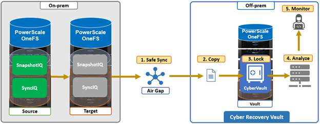
The combination of OneFS snapshots and SyncIQ replication allows for granular data recovery. This means that only the affected files are recovered, while the most recent changes are preserved for the unaffected data. While an on-prem air-gapped cyber vault can still provide secure network isolation, in the event of an attack, the ability to failover to a fully operational ‘clean slate’ remote site provides additional security and peace of mind.
We’ll explore PowerScale cyber protection and recovery in more depth in a future article.
Author: Nick Trimbee

OneFS SupportAssist Architecture and Operation
Fri, 21 Apr 2023 16:41:36 -0000
|Read Time: 0 minutes
The previous article in this series looked at an overview of OneFS SupportAssist. Now, we’ll turn our attention to its core architecture and operation.
Under the hood, SupportAssist relies on the following infrastructure and services:
Service | Name |
ESE | Embedded Service Enabler. |
isi_rice_d | Remote Information Connectivity Engine (RICE). |
isi_crispies_d | Coordinator for RICE Incidental Service Peripherals including ESE Start. |
Gconfig | OneFS centralized configuration infrastructure. |
MCP | Master Control Program – starts, monitors, and restarts OneFS services. |
Tardis | Configuration service and database. |
Transaction journal | Task manager for RICE. |
Of these, ESE, isi_crispies_d, isi_rice_d, and the Transaction Journal are new in OneFS 9.5 and exclusive to SupportAssist. By contrast, Gconfig, MCP, and Tardis are all legacy services that are used by multiple other OneFS components.
The Remote Information Connectivity Engine (RICE) represents the new SupportAssist ecosystem for OneFS to connect to the Dell backend. The high level architecture is as follows:
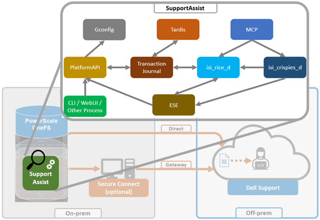
Dell’s Embedded Service Enabler (ESE) is at the core of the connectivity platform and acts as a unified communications broker between the PowerScale cluster and Dell Support. ESE runs as a OneFS service and, on startup, looks for an on-premises gateway server. If none is found, it connects back to the connectivity pipe (SRS). The collector service then interacts with ESE to send telemetry, obtain upgrade packages, transmit alerts and events, and so on.
Depending on the available resources, ESE provides a base functionality with additional optional capabilities to enhance serviceability. ESE is multithreaded, and each payload type is handled by specific threads. For example, events are handled by event threads, binary and structured payloads are handled by web threads, and so on. Within OneFS, ESE gets installed to /usr/local/ese and runs as ‘ese’ user and group.
The responsibilities of isi_rice_d include listening for network changes, getting eligible nodes elected for communication, monitoring notifications from CRISPIES, and engaging Task Manager when ESE is ready to go.
The Task Manager is a core component of the RICE engine. Its responsibility is to watch the incoming tasks that are placed into the journal and to assign workers to step through the tasks until completion. It controls the resource utilization (Python threads) and distributes tasks that are waiting on a priority basis.
The ‘isi_crispies_d’ service exists to ensure that ESE is only running on the RICE active node, and nowhere else. It acts, in effect, like a specialized MCP just for ESE and RICE-associated services, such as IPA. This entails starting ESE on the RICE active node, re-starting it if it crashes on the RICE active node, and stopping it and restarting it on the appropriate node if the RICE active instance moves to another node. We are using ‘isi_crispies_d’ for this, and not MCP, because MCP does not support a service running on only one node at a time.
The core responsibilities of ‘isi_crispies_d’ include:
- Starting and stopping ESE on the RICE active node
- Monitoring ESE and restarting, if necessary. ‘isi_crispies_d’ restarts ESE on the node if it crashes. It will retry a couple of times and then notify RICE if it’s unable to start ESE.
- Listening for gconfig changes and updating ESE. Stopping ESE if unable to make a change and notifying RICE.
- Monitoring other related services.
The state of ESE, and of other RICE service peripherals, is stored in the OneFS tardis configuration database so that it can be checked by RICE. Similarly, ‘isi_crispies_d’ monitors the OneFS Tardis configuration database to see which node is designated as the RICE ‘active’ node.
The ‘isi_telemetry_d’ daemon is started by MCP and runs when SupportAssist is enabled. It does not have to be running on the same node as the active RICE and ESE instance. Only one instance of ‘isi_telemetry_d’ will be active at any time, and the other nodes will be waiting for the lock.
You can query the current status and setup of SupportAssist on a PowerScale cluster by using the ‘isi supportassist settings view’ CLI command. For example:
# isi supportassist settings view
        Service enabled: Yes
       Connection State: enabled
      OneFS Software ID: ELMISL08224764
          Network Pools: subnet0:pool0
        Connection mode: direct
           Gateway host: -
           Gateway port: -
    Backup Gateway host: -
    Backup Gateway port: -
  Enable Remote Support: Yes
Automatic Case Creation: Yes
       Download enabled: Yes
You can also do this from the WebUI by navigating to Cluster management > General settings > SupportAssist:
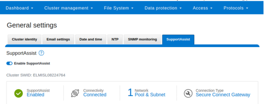
You can enable or disable SupportAssist by using the ‘isi services’ CLI command set. For example:
# isi services isi_supportassist disable
The service 'isi_supportassist' has been disabled.
# isi services isi_supportassist enable
The service 'isi_supportassist' has been enabled.
# isi services -a | grep supportassist
   isi_supportassist    SupportAssist Monitor                    Enabled
You can check the core services, as follows:
# ps -auxw | grep -e 'rice' -e 'crispies' | grep -v grep
root    8348    9.4   0.0 109844  60984  -   Ss   22:14        0:00.06 /usr/libexec/isilon/isi_crispies_d /usr/bin/isi_crispies_d
root    8183    8.8   0.0 108060  64396  -   Ss   22:14        0:01.58 /usr/libexec/isilon/isi_rice_d /usr/bin/isi_rice_d
Note that when a cluster is provisioned with SupportAssist, ESRS can no longer be used. However, customers that have not previously connected their clusters to Dell Support can still provision ESRS, but will be presented with a message encouraging them to adopt the best practice of using SupportAssist.
Additionally, SupportAssist in OneFS 9.5 does not currently support IPv6 networking, so clusters deployed in IPv6 environments should continue to use ESRS until SupportAssist IPv6 integration is introduced in a future OneFS release.
Author: Nick Trimbee

OneFS SupportAssist Management and Troubleshooting
Tue, 18 Apr 2023 20:07:18 -0000
|Read Time: 0 minutes
In this final article in the OneFS SupportAssist series, we turn our attention to management and troubleshooting.
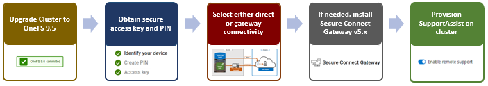
Once the provisioning process above is complete, the isi supportassist settings view CLI command reports the status and health of SupportAssist operations on the cluster.
# isi supportassist settings view
        Service enabled: Yes
       Connection State: enabled
      OneFS Software ID: xxxxxxxxxx
          Network Pools: subnet0:pool0
        Connection mode: direct
           Gateway host: -
           Gateway port: -
    Backup Gateway host: -
    Backup Gateway port: -
  Enable Remote Support: Yes
Automatic Case Creation: Yes
       Download enabled: Yes
This can also be obtained from the WebUI by going to Cluster management > General settings > SupportAssist:
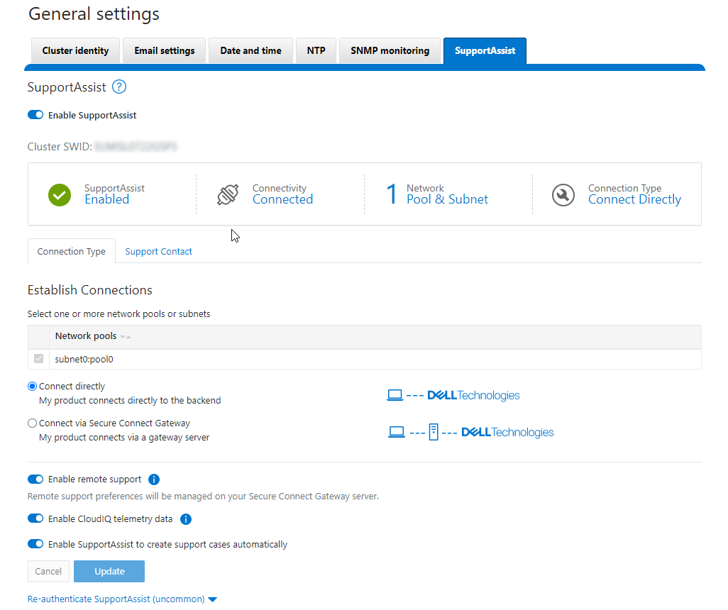
There are some caveats and considerations to keep in mind when upgrading to OneFS 9.5 and enabling SupportAssist, including:
- SupportAssist is disabled when STIG hardening is applied to a cluster.
- Using SupportAssist on a hardened cluster is not supported.
- Clusters with the OneFS network firewall enabled (isi network firewall settings) might need to allow outbound traffic on port 9443.
- SupportAssist is supported on a cluster that’s running in Compliance mode.
- Secure keys are held in key manager under the RICE domain.
Also, note that Secure Remote Services can no longer be used after SupportAssist has been provisioned on a cluster.
SupportAssist has a variety of components that gather and transmit various pieces of OneFS data and telemetry to Dell Support and backend services through the Embedded Service Enabler (ESE). These workflows include CELOG events; in-product activation (IPA) information; CloudIQ telemetry data; Isi-Gather-info (IGI) logsets; and provisioning, configuration, and authentication data to ESE and the various backend services.
Activity | Information |
Events and alerts | SupportAssist can be configured to send CELOG events. |
Diagnostics | The OneFS isi diagnostics gather and isi_gather_info logfile collation and transmission commands have a SupportAssist option. |
HealthChecks | HealthCheck definitions are updated using SupportAssist. |
License Activation | The isi license activation start command uses SupportAssist to connect. |
Remote Support | Remote Support uses SupportAssist and the Connectivity Hub to assist customers with their clusters. |
Telemetry | CloudIQ telemetry data is sent using SupportAssist. |
CELOG
Once SupportAssist is up and running, it can be configured to send CELOG events and attachments through ESE to CLM. This can be managed by the isi event channels CLI command syntax. For example:
# isi event channels list
ID   Name                Type          Enabled
-----------------------------------------------
1    RemoteSupport       connectemc    No
2    Heartbeat Self-Test heartbeat     Yes
3    SupportAssist       supportassist No
-----------------------------------------------
Total: 3
# isi event channels view SupportAssist
     ID: 3
   Name: SupportAssist
   Type: supportassist
Enabled: No
Or from the WebUI:
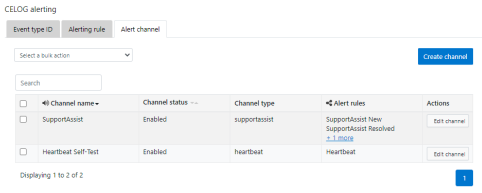
CloudIQ telemetry
In OneFS 9.5, SupportAssist provides an option to send telemetry data to CloudIQ. This can be enabled from the CLI as follows:
# isi supportassist telemetry modify --telemetry-enabled 1 --telemetry-persist 0
# isi supportassist telemetry view
        Telemetry Enabled: Yes
        Telemetry Persist: No
        Telemetry Threads: 8
Offline Collection Period: 7200
Or in the SupportAssist WebUI:
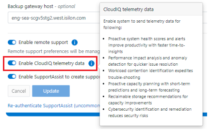
Diagnostics gather
Also in OneFS 9.5, the isi diagnostics gather and isi_gather_info CLI commands both include a --supportassist upload option for log gathers, which also allows them to continue to function through a new “emergency mode” when the cluster is unhealthy. For example, to start a gather from the CLI that will be uploaded through SupportAssist:
# isi diagnostics gather start –supportassist 1
Similarly, for ISI gather info:
# isi_gather_info --supportassist
Or to explicitly avoid using SupportAssist for ISI gather info log gather upload:
# isi_gather_info --nosupportassist
This can also be configured from the WebUI at Cluster management > General configuration > Diagnostics > Gather:
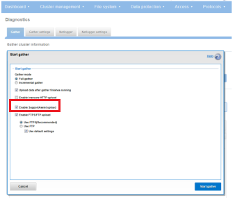
License Activation through SupportAssist
PowerScale License Activation (previously known as In-Product Activation) facilitates the management of the cluster's entitlements and licenses by communicating directly with Software Licensing Central through SupportAssist.
To activate OneFS product licenses through the SupportAssist WebUI:
- Go to Cluster management > Licensing.
For example, on a new cluster without any signed licenses: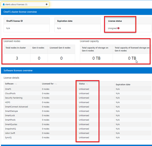
- Click the Update & Refresh button in the License Activation section. In the Activation File Wizard, select the software modules that you want in the activation file.
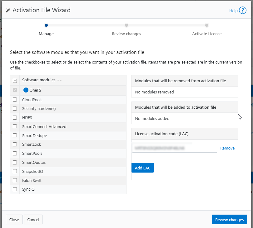
- Select Review changes, review, click Proceed, and finally Activate
Note that it can take up to 24 hours for the activation to occur.
Alternatively, cluster license activation codes (LAC) can also be added manually.
Troubleshooting
When it comes to troubleshooting SupportAssist, the basic process flow is as follows:
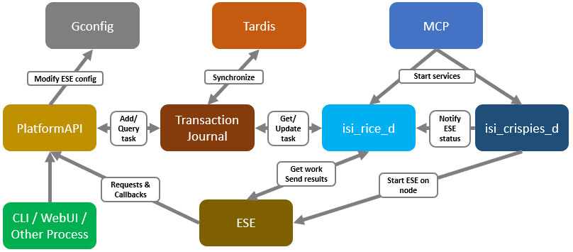
The OneFS components and services above are:
Component | Info |
ESE | Embedded Service Enabler |
isi_rice_d | Remote Information Connectivity Engine (RICE) |
isi_crispies_d | Coordinator for RICE Incidental Service Peripherals including ESE Start |
Gconfig | OneFS centralized configuration infrastructure |
MCP | Master Control Program; starts, monitors, and restarts OneFS services |
Tardis | Configuration service and database |
Transaction journal | Task manager for RICE |
Of these, ESE, isi_crispies_d, isi_rice_d, and the transaction journal are new in OneFS 9.5 and exclusive to SupportAssist. In contrast, Gconfig, MCP, and Tardis are all legacy services that are used by multiple other OneFS components.
For its connectivity, SupportAssist elects a single leader single node within the subnet pool, and NANON nodes are automatically avoided. Ports 443 and 8443 are required to be open for bi-directional communication between the cluster and Connectivity Hub, and port 9443 is for communicating with a gateway. The SupportAssist ESE component communicates with a number of Dell backend services:
- SRS
- Connectivity Hub
- CLM
- ELMS/Licensing
- SDR
- Lightning
- Log Processor
- CloudIQ
- ESE
Debugging backend issues might involve one or more services, and Dell Support can assist with this process.
The main log files for investigating and troubleshooting SupportAssist issues and idiosyncrasies are isi_rice_d.log and isi_crispies_d.log. There is also an ese_log, which can be useful, too. These logs can be found at:
Component | Logfile location | Info |
Rice | /var/log/isi_rice_d.log | Per node |
Crispies | /var/log/isi_crispies_d.log | Per node |
ESE | /ifs/.ifsvar/ese/var/log/ESE.log | Cluster-wide for single instance ESE |
Debug level logging can be configured from the CLI as follows:
# isi_for_array isi_ilog -a isi_crispies_d --level=debug+
# isi_for_array isi_ilog -a isi_rice_d --level=debug+
Note that the OneFS log gathers (such as the output from the isi_gather_info utility) will capture all the above log files, plus the pertinent SupportAssist Gconfig contexts and Tardis namespaces, for later analysis.
If needed, the Rice and ESE configurations can also be viewed as follows:
# isi_gconfig -t ese
[root] {version:1}
ese.mode (char*) = direct
ese.connection_state (char*) = disabled
ese.enable_remote_support (bool) = true
ese.automatic_case_creation (bool) = true
ese.event_muted (bool) = false
ese.primary_contact.first_name (char*) =
ese.primary_contact.last_name (char*) =
ese.primary_contact.email (char*) =
ese.primary_contact.phone (char*) =
ese.primary_contact.language (char*) =
ese.secondary_contact.first_name (char*) =
ese.secondary_contact.last_name (char*) =
ese.secondary_contact.email (char*) =
ese.secondary_contact.phone (char*) =
ese.secondary_contact.language (char*) =
(empty dir ese.gateway_endpoints)
ese.defaultBackendType (char*) = srs
ese.ipAddress (char*) = 127.0.0.1
ese.useSSL (bool) = true
ese.srsPrefix (char*) = /esrs/{version}/devices
ese.directEndpointsUseProxy (bool) = false
ese.enableDataItemApi (bool) = true
ese.usingBuiltinConfig (bool) = false
ese.productFrontendPrefix (char*) = platform/16/supportassist
ese.productFrontendType (char*) = webrest
ese.contractVersion (char*) = 1.0
ese.systemMode (char*) = normal
ese.srsTransferType (char*) = ISILON-GW
ese.targetEnvironment (char*) = PROD

# isi_gconfig -t rice
[root] {version:1}
rice.enabled (bool) = false
rice.ese_provisioned (bool) = false
rice.hardware_key_present (bool) = false
rice.supportassist_dismissed (bool) = false
rice.eligible_lnns (char*) = []
rice.instance_swid (char*) =
rice.task_prune_interval (int) = 86400
rice.last_task_prune_time (uint) = 0
rice.event_prune_max_items (int) = 100
rice.event_prune_days_to_keep (int) = 30
rice.jnl_tasks_prune_max_items (int) = 100
rice.jnl_tasks_prune_days_to_keep (int) = 30
rice.config_reserved_workers (int) = 1
rice.event_reserved_workers (int) = 1
rice.telemetry_reserved_workers (int) = 1
rice.license_reserved_workers (int) = 1
rice.log_reserved_workers (int) = 1
rice.download_reserved_workers (int) = 1
rice.misc_task_workers (int) = 3
rice.accepted_terms (bool) = false
(empty dir rice.network_pools)
rice.telemetry_enabled (bool) = true
rice.telemetry_persist (bool) = false
rice.telemetry_threads (uint) = 8
rice.enable_download (bool) = true
rice.init_performed (bool) = false
rice.ese_disconnect_alert_timeout (int) = 14400
rice.offline_collection_period (uint) = 7200
The -q flag can also be used in conjunction with the isi_gconfig command to identify any values that are not at their default settings. For example, the stock (default) Rice gconfig context will not report any configuration entries:
# isi_gconfig -q -t rice
[root] {version:1}

OneFS SupportAssist Provisioning – Part 2
Thu, 13 Apr 2023 21:29:24 -0000
|Read Time: 0 minutes
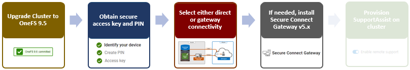
- Upgrading the cluster to OneFS 9.5.
- Obtaining the secure access key and PIN.
- Selecting either direct connectivity or gateway connectivity.
- If using gateway connectivity, installing Secure Connect Gateway v5.x.
In this article, we turn our attention to step 5: Provisioning SupportAssist on the cluster.
As part of this process, we’ll be using the access key and PIN credentials previously obtained from the Dell Support portal in step 2 above.
Provisioning SupportAssist on a cluster
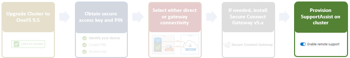
SupportAssist can be configured from the OneFS 9.5 WebUI by going to Cluster management > General settings > SupportAssist. To initiate the provisioning process on a cluster, click the Connect SupportAssist link, as shown here:
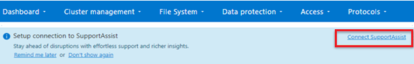
If SupportAssist is not configured, the Remote support page displays the following banner, warning of the future deprecation of SRS:
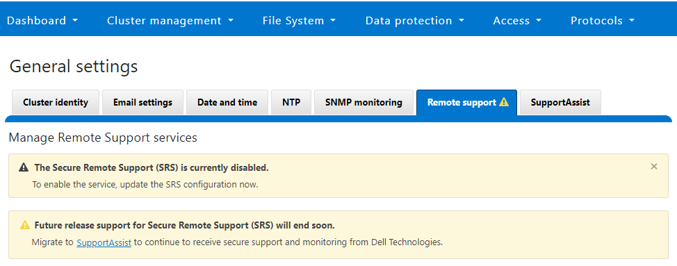
Similarly, when SupportAssist is not configured, the SupportAssist WebUI page also displays verbiage recommending the adoption of SupportAssist:
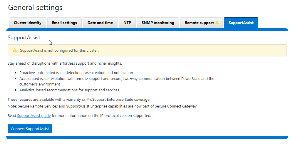
There is also a Connect SupportAssist button to begin the provisioning process.
Selecting the Configure SupportAssist button initiates the setup wizard.
1. Telemetry Notice
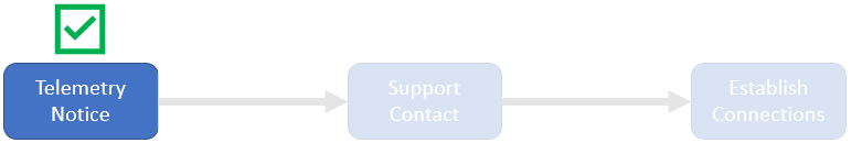
The first step requires checking and accepting the Infrastructure Telemetry Notice:
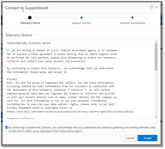
2. Support Contract
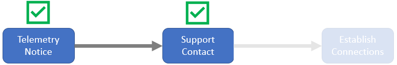
For the next step, enter the details for the primary support contact, as prompted:

You can also provide the information from the CLI by using the isi supportassist contacts command set. For example:
# isi supportassist contacts modify --primary-first-name=Nick --primary-last-name=Trimbee --primary-email=trimbn@isilon.com
3. Establish Connections
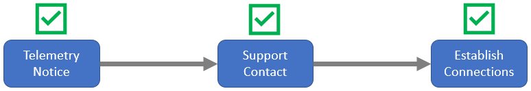
Next, complete the Establish Connections page
This involves the following steps:

- Selecting the network pool(s)
- Adding the secure access key and PIN
- Configuring either direct or gateway access
- Selecting whether to allow remote support, CloudIQ telemetry, and auto case creation
a. Select network pool(s).

At least one statically allocated IPv4 network subnet and pool are required for provisioning SupportAssist. OneFS 9.5 does not support IPv6 networking for SupportAssist remote connectivity. However, IPv6 support is planned for a future release.
Select one or more network pools or subnets from the options displayed. In this example, we select subnet0pool0:
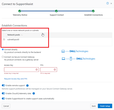
Or from the CLI:
Select one or more static subnets or pools for outbound communication, using the following CLI syntax:
# isi supportassist settings modify --network-pools="subnet0.pool0"
Additionally, if the cluster has the OneFS 9.5 network firewall enabled (“isi network firewall settings”), ensure that outbound traffic is allowed on port 9443.
b. Add secure access key and PIN.

In this next step, add the secure access key and pin. These should have been obtained in an earlier step in the provisioning procedure from the following Dell Support site: https://www.dell.com/support/connectivity/product/isilon-onefs.

Alternatively, if configuring SupportAssist from the OneFS CLI, add the key and pin by using the following syntax:
# isi supportassist provision start --access-key <key> --pin <pin>
c. Configure access.
- Direct access

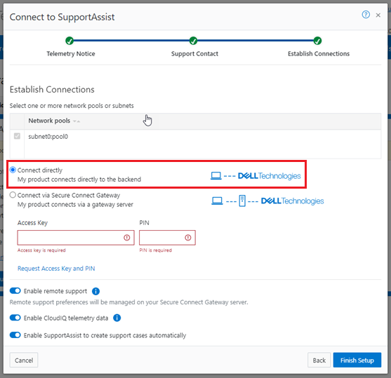
Or, to configure direct access (the default) from the CLI, ensure that the following parameter is set:
# isi supportassist settings modify --connection-mode direct
# isi supportassist settings view | grep -i "connection mode"
        Connection mode: direct
- Gateway access

Alternatively, to connect through a gateway, select the Connect via Secure Connect Gateway button:
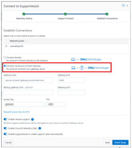
Complete the Gateway host and Gateway port fields as appropriate for the environment.
Alternatively, to set up a gateway configuration from the CLI, use the isi supportassist settings modify syntax. For example, to use the gateway FQDN secure-connect-gateway.yourdomain.com and the default port 9443:
# isi supportassist settings modify --connection-mode gateway
# isi supportassist settings view | grep -i "connection mode"
        Connection mode: gateway
# isi supportassist settings modify --gateway-host secure-connect-gateway.yourdomain.com --gateway-port 9443
When setting up the gateway connectivity option, Secure Connect Gateway v5.0 or later must be deployed within the data center. SupportAssist is incompatible with either ESRS gateway v3.52 or SAE gateway v4. However, Secure Connect Gateway v5.x is backward compatible with PowerScale OneFS ESRS, which allows the gateway to be provisioned and configured ahead of a cluster upgrade to OneFS 9.5.
d. Configure support options.

Finally, configure the support options:

When you have completed the configuration, the WebUI will confirm that SmartConnect is successfully configured and enabled, as follows:
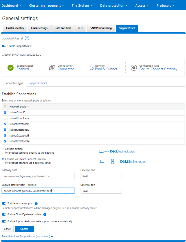
Or from the CLI:
# isi supportassist settings view
        Service enabled: Yes
       Connection State: enabled
      OneFS Software ID: ELMISL0223BJJC
          Network Pools: subnet0.pool0, subnet0.testpool1, subnet0.testpool2, subnet0.testpool3, subnet0.testpool4
        Connection mode: gateway
           Gateway host: eng-sea-scgv5stg3.west.isilon.com
           Gateway port: 9443
    Backup Gateway host: eng-sea-scgv5stg.west.isilon.com
    Backup Gateway port: 9443
  Enable Remote Support: Yes
Automatic Case Creation: Yes
       Download enabled: Yes

OneFS SupportAssist Provisioning – Part 1
Thu, 13 Apr 2023 20:20:31 -0000
|Read Time: 0 minutes
In OneFS 9.5, several OneFS components now leverage SupportAssist as their secure off-cluster data retrieval and communication channel. These components include:
| Component | Details |
|---|---|
Events and Alerts | SupportAssist can send CELOG events and attachments through Embedded Service Enabler (ESE) to CLM. |
Diagnostics | Logfile gathers can be uploaded to Dell through SupportAssist. |
License activation | License activation uses SupportAssist for the isi license activation start CLI command. |
Telemetry | Telemetry is sent through SupportAssist to CloudIQ for analytics. |
Health check | Health check definition downloads now leverage SupportAssist. |
Remote Support | Remote Support now uses SupportAssist along with Connectivity Hub. |
For existing clusters, SupportAssist supports the same basic workflows as its predecessor, ESRS, so the transition from old to new is generally pretty seamless.
The overall process for enabling OneFS SupportAssist is as follows:

- Upgrade the cluster to OneFS 9.5.
- Obtain the secure access key and PIN.
- Select either direct connectivity or gateway connectivity.
- If using gateway connectivity, install Secure Connect Gateway v5.x.
- Provision SupportAssist on the cluster.
We’ll go through each of these configuration steps in order:
1. Upgrading to OneFS 9.5
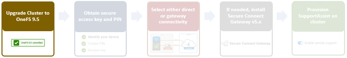
First, the cluster must be running OneFS 9.5 to configure SupportAssist.
There are some additional considerations and caveats to bear in mind when upgrading to OneFS 9.5 and planning on enabling SupportAssist. These include:
- SupportAssist is disabled when STIG hardening is applied to the cluster.
- Using SupportAssist on a hardened cluster is not supported.
- Clusters with the OneFS network firewall enabled (”isi network firewall settings”) might need to allow outbound traffic on ports 443 and 8443, plus 9443 if gateway (SCG) connectivity is configured.
- SupportAssist is supported on a cluster that’s running in Compliance mode.
- If you are upgrading from an earlier release, the OneFS 9.5 upgrade must be committed before SupportAssist can be provisioned.
Also, ensure that the user account that will be used to enable SupportAssist belongs to a role with the ISI_PRIV_REMOTE_SUPPORT read and write privilege:
# isi auth privileges | grep REMOTE
ISI_PRIV_REMOTE_SUPPORT
  Configure remote support
For example, for an ese user account:
# isi auth roles view SupportAssistRole
       Name: SupportAssistRole
Description: -
    Members: ese
 Privileges
             ID: ISI_PRIV_LOGIN_PAPI
     Permission: r
             ID: ISI_PRIV_REMOTE_SUPPORT
      Permission: w
2. Obtaining secure access key and PIN
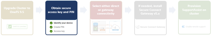
An access key and pin are required to provision SupportAssist, and these secure keys are held in key manager under the RICE domain. This access key and pin can be obtained from the following Dell Support site: https://www.dell.com/support/connectivity/product/isilon-onefs.
In the Quick link navigation bar, select the Generate Access key link:
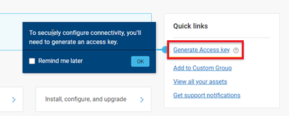
On the following page, select the appropriate button:
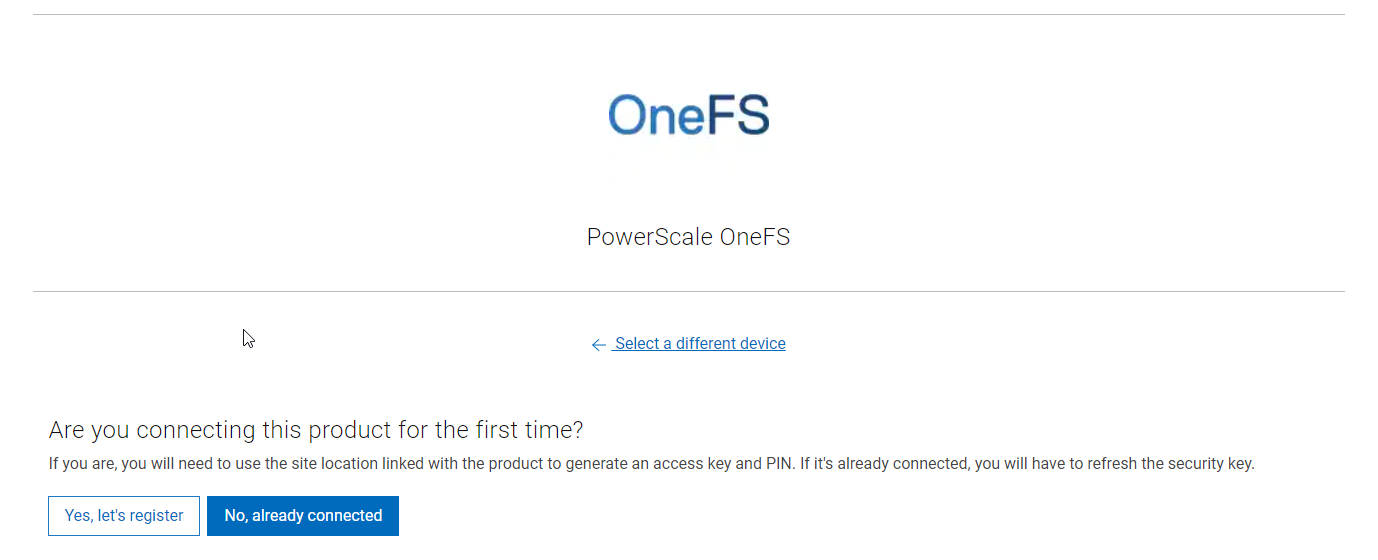
The credentials required to obtain an access key and pin vary, depending on prior cluster configuration. Sites that have previously provisioned ESRS will need their OneFS Software ID (SWID) to obtain their access key and pin.
The isi license list CLI command can be used to determine a cluster’s SWID. For example:
# isi license list | grep "OneFS Software ID"
OneFS Software ID: ELMISL999CKKD
However, customers with new clusters and/or customers who have not previously provisioned ESRS or SupportAssist will require their Site ID to obtain the access key and pin.
Note that any new cluster hardware shipping after January 2023 will already have an integrated key, so this key can be used in place of the Site ID.
For example, if this is the first time registering this cluster and it does not have an integrated key, select Yes, let’s register:
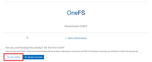
Enter the Site ID, site name, and location information for the cluster:
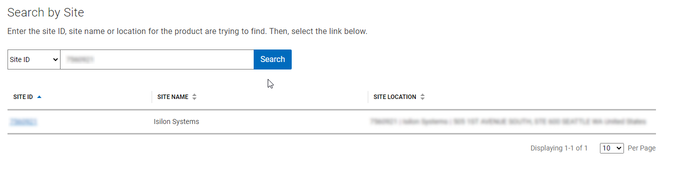
Choose a 4-digit PIN and save it for future reference. After that, click Create My Access Key:
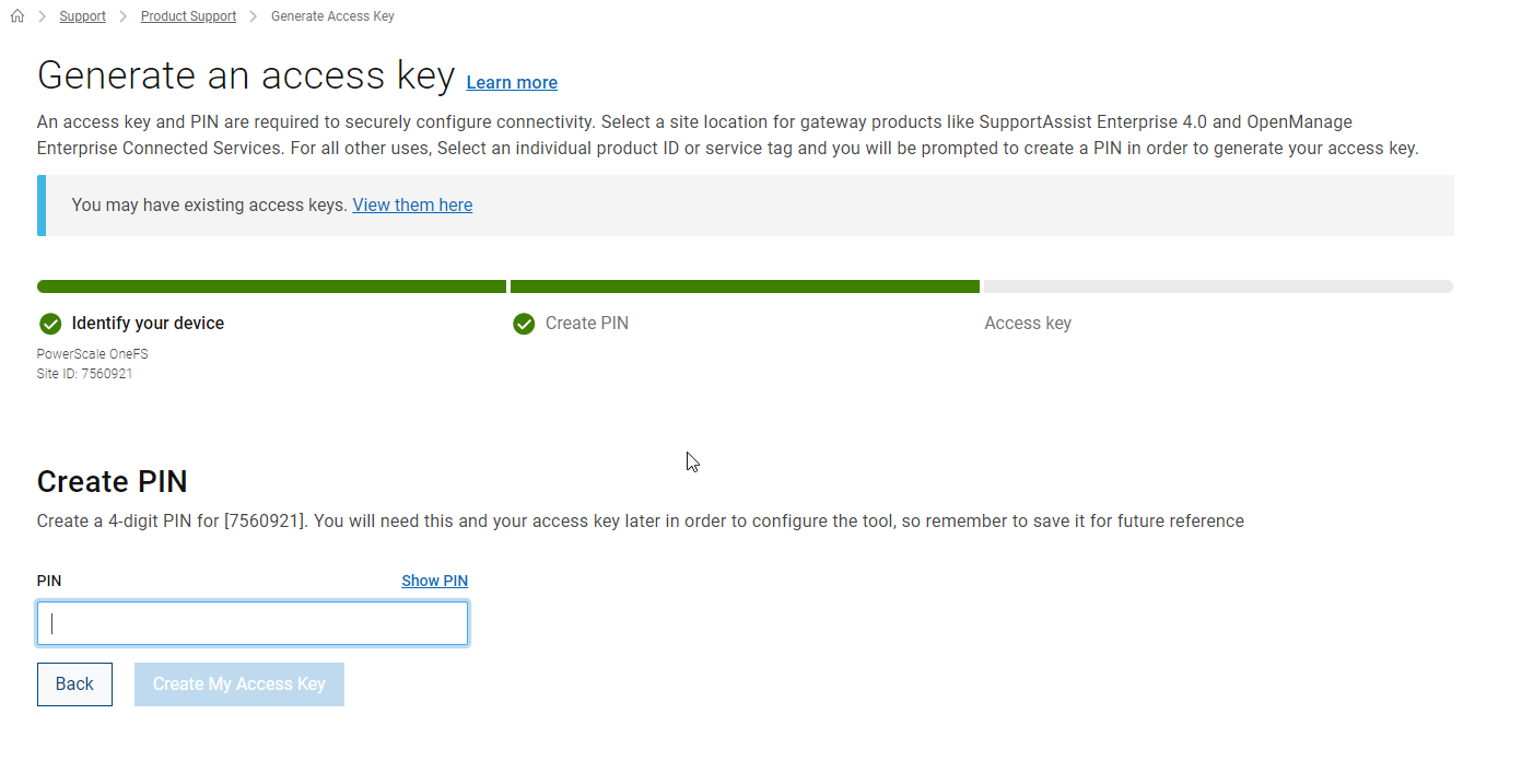
The access key is then generated.
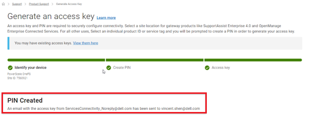
An automated email containing the pertinent key info is sent from the Dell | ServicesConnectivity Team. For example:
This access key is valid for one week, after which it automatically expires.
Next, in the cluster’s WebUI, go back to Cluster management > General settings > SupportAssist and enter the access key and PIN information in the appropriate fields. Finally, click Finish Setup to complete the SupportAssist provisioning process:
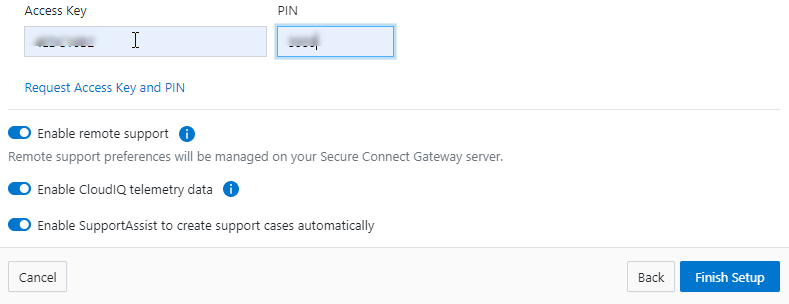
3. Deciding between direct or gateway topology
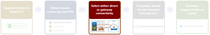
A topology decision will need to be made between implementing either direct connectivity or gateway connectivity, depending on the needs of the environment:
- Direct connect:
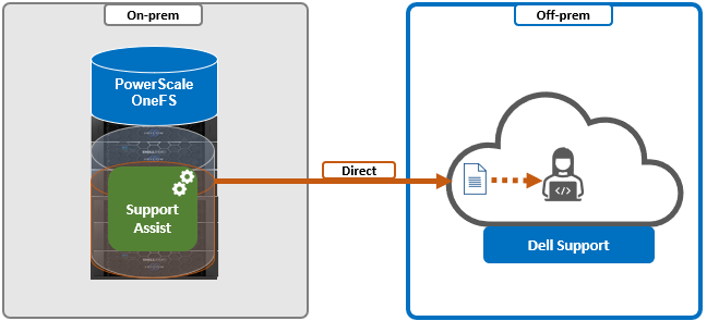
- Gateway connect:
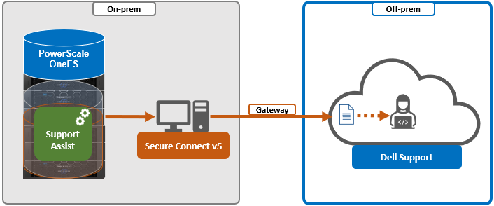
SupportAssist uses ports 443 and 8443 by default for bi-directional communication between the cluster and Connectivity Hub. These ports will need to be open across any firewalls or packet filters between the cluster and the corporate network edge to allow connectivity to Dell Support.
Additionally, port 9443 is used for communicating with a gateway (SCG).
# grep -i esrs /etc/services
isi_esrs_d      9443/tcp   #EMC Secure Remote Support outbound alerts
4. Installing Secure Connect Gateway (optional)
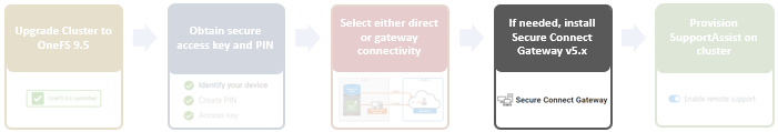
This step is only required when deploying Dell Secure Connect Gateway (SCG). If a direct connect topology is preferred, go directly to step 5.
When configuring SupportAssist with the gateway connectivity option, Secure Connect Gateway v5.0 or later must be deployed within the data center.
Dell SCG is available for Linux, Windows, Hyper-V, and VMware environments, and, as of this writing, the latest version is 5.14.00.16. The installation binaries can be downloaded from https://www.dell.com/support/home/en-us/product-support/product/secure-connect-gateway/drivers.
Download SCG as follows:
- Sign in to www.dell.com/SCG-App. The Secure Connect Gateway - Application Edition page is displayed. If you have issues signing in using your business account or if you are unable to access the page even after signing in, contact Dell Administrative Support.
- In the Quick links section, click Generate Access key.
- On the Generate Access Keypage, perform the following steps:
- Select a site ID, site name, or site location.
- Enter a four-digit PIN and click Generate key. An access key is generated and sent to your email address. NOTE: The access key and PIN must be used within seven days and cannot be used to register multiple instances of SCG.
- Click Done.
- On the Secure Connect Gateway – Application Edition page, click the Drivers & Downloads tab.
- Search and select the required version.
- In the ACTION column, click Download.
The following steps are required to set up SCG:
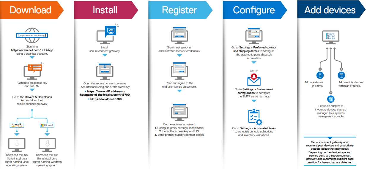
Pertinent resources for installing SCG include:
- Users guide, for system and network requirements, steps to create business account, and installation instructions: https://www.dell.com/SCG-App-docs
- Support matrix, for supported devices, protocols, firmware versions, and operating systems: https://www.dell.com/SCG-App-docs
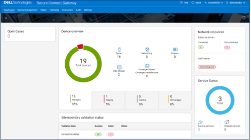
Another useful source of SCG installation, configuration, and troubleshooting information is the Dell Support forum: https://www.dell.com/community/Secure-Connect-Gateway/bd-p/SCG
5. Provisioning SupportAssist on the cluster

At this point, the off-cluster prestaging work should be complete.
In the next article in this series, we turn our attention to the SupportAssist provisioning process on the cluster itself (step 5).

Dell PowerScale OneFS Introduction for NetApp Admins
Tue, 04 Apr 2023 17:15:00 -0000
|Read Time: 0 minutes
For enterprises to harness the advantages of advanced storage technologies with Dell PowerScale, a transition from an existing platform is necessary. Enterprises are challenged by how the new architecture will fit into the existing infrastructure. This blog post provides an overview of PowerScale architecture, features, and nomenclature for enterprises migrating from NetApp ONTAP.
PowerScale overview
The PowerScale OneFS operating system is based on a distributed architecture, built from the ground up as a clustered system. Each PowerScale node provides compute, memory, networking, and storage. The concepts of controllers, HA, active/standby, and disk shelves are not applicable in a pure scale-out architecture. Thus, when a node is added to a cluster, the cluster performance and capacity increase collectively.
Due to the scale-out distributed architecture with a single namespace, single volume, single file system, and one single pane of management, the system management is far simpler than with traditional NAS platforms. In addition, the data protection is software-based rather than RAID-based, eliminating all the associated complexities, including configuration, maintenance, and additional storage utilization. Administrators do not have to be concerned with RAID groups or load distribution.
NetApp’s ONTAP storage operating system has evolved into a clustered system with controllers. The system includes ONTAP FlexGroups composed of aggregates and FlexVols across nodes.
OneFS is a single volume, which makes cluster management simple. As the cluster grows in capacity, the single volume automatically grows. Administrators are no longer required to migrate data between volumes manually. OneFS repopulates and balances data between all nodes when a new node is added, making the node part of the global namespace. All the nodes in a PowerScale cluster are equal in the hierarchy. Drives share data intranode and internode.
PowerScale is easy to deploy, operate, and manage. Most enterprises require only one full-time employee to manage a PowerScale cluster.
For more information about the PowerScale OneFS architecture, see PowerScale OneFS Technical Overview and Dell PowerScale OneFS Operating System.
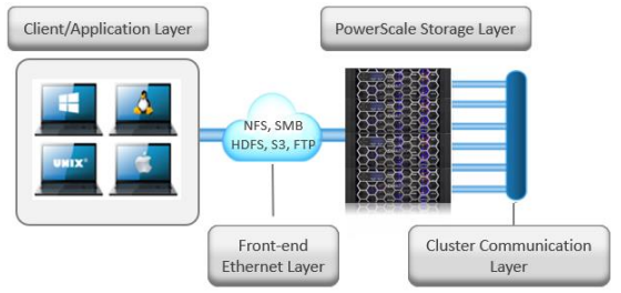
Figure 1. Dell PowerScale scale-out NAS architecture
OneFS and NetApp software features
The single volume and single namespace of PowerScale OneFS also lead to a unique feature set. Because the entire NAS is a single file system, the concepts of FlexVols, shares, qtrees, and FlexGroups do not apply. Each NetApp volume has specific properties associated with limited storage space. Adding more storage space to NetApp ONTAP could be an onerous process depending on the current architecture. Conversely, on a PowerScale cluster, as soon as a node is added, the cluster is rebalanced automatically, leading to minimal administrator management.
NetApp’s continued dependence on volumes creates potential added complexity for storage administrators. From a software perspective, the intricacies that arise from the concept of volumes span across all the features. Configuring software features requires administrators to base decisions on the volume concept, limiting configuration options. The volume concept is further magnified by the impacts on storage utilization.
The fact that OneFS is a single volume means that many features are not volume dependent but, rather, span the entire cluster. SnapshotIQ, NDMP backups, and SmartQuotas do not have limits based on volumes; instead, they are cluster-specific or directory-specific.
As a single-volume NAS designed for file storage, OneFS has the scalable capacity with ease of management combined with features that administrators require. Robust policy-driven features such as SmartConnect, SmartPools, and CloudPools enable maximum utilization of nodes for superior performance and storage efficiency for maximum value. You can use SmartConnect to configure access zones that are mapped to specific node performances. SmartPools can tier cold data to nodes with deep archive storage, and CloudPools can store frozen data in the cloud. Regardless of where the data is residing, it is presented as a single namespace to the end user.
Storage utilization and data protection
Storage utilization is the amount of storage available after the NAS system overhead is deducted. The overhead consists of the space required for data protection and the operating system.
For data protection, OneFS uses software-based Reed-Solomon Error Correction with up to N+4 protection. OneFS offers several custom protection options that cover node and drive failures. The custom protection options vary according to the cluster configuration. OneFS provides data protection against more simultaneous hardware failures and is software-based, providing a significantly higher storage utilization.
The software-based data protection stripes data across nodes in stripe units, and some of the stripe units are Forward Error Correction (FEC) or parity units. The FEC units provide a variable to reformulate the data in the case of a drive or node failure. Data protection is customizable to be for node loss or hybrid protection of node and drive failure.
With software-based data protection, the protection scheme is not per cluster. It has additional granularity that allows for making data protection specific to a file or directory—without creating additional storage volumes or manually migrating data. Instead, OneFS runs a job in the background, moving data as configured.
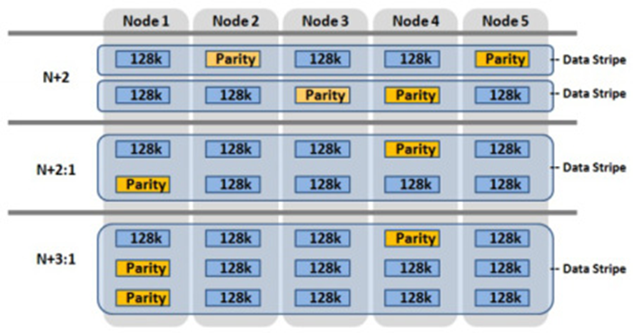
Figure 2. OneFS data protection
OneFS protects data stored on failing nodes, or drives in a cluster through a process called SmartFail. During the process, OneFS places a device into quarantine and, depending on the severity of the issue, places the data on the device into a read-only state. While a device is quarantined, OneFS reprotects the data on the device by distributing the data to other devices.
NetApp’s data protection is all RAID-based, including NetApp RAID-TEC, NetApp RAID-DP, and RAID 4. NetApp only supports a maximum of triple parity, and simultaneous node failures in an HA pair are not supported.
For more information about SmartFail, see the following blog: OneFS Smartfail. For more information about OneFS data protection, see High Availability and Data Protection with Dell PowerScale Scale-Out NAS.
NetApp FlexVols, shares, and Qtrees
NetApp requires administrators to manually create space and explicitly define aggregates and flexible volumes. The concept of FlexVols, shares, and Qtrees are nonexistent in OneFS, as the file system is a single volume and namespace, spanning the entire cluster.
SMB shares and NFS exports are created through the web or command-line interface in OneFS. Both methods allow the user to create either within seconds with security options. SmartQuotas is used to manage storage limits, cluster-wide, across the entire namespace. They include accounting, warning messages, or hard limits of enforcement. The limits can be applied by directory, user, or group.
Conversely, ONTAP quota management is at the volume or FlexGroup level, creating additional administrative overhead because the process is more onerous.
Snapshots
The OneFS snapshot feature is SnapshotIQ, which does not have specified or enforced limits for snapshots per directory or snapshots per cluster. However, the best practice is 1,024 snapshots per directory and 20,000 snapshots per cluster. OneFS also supports writable snapshots. For more information about SnapshotIQ and writable snapshots, see High Availability and Data Protection with Dell PowerScale Scale-Out NAS.
NetApp Snapshot supports 255 snapshots per volume in ONTAP 9.3 and earlier. ONTAP 9.4 and later versions support 1,023 snapshots per volume. By default, NetApp requires a space reservation of 5 percent in the volume when snapshots are used, requiring the space reservation to be monitored and manually increased if space becomes exhausted. Further, the space reservation can also affect volume availability. The space reservation requirement creates additional administration overhead and affects storage efficiency by setting aside space that might or might not be used.
Data replication
Data replication is required for disaster recovery, RPO, or RTO requirements. OneFS provides data replication through SyncIQ and SmartSync.
SyncIQ provides asynchronous data replication, whereas NetApp’s asynchronous replication, which is called SnapMirror, is block-based replication. SyncIQ provides options for ensuring that all data is retained during failover and failback from the disaster recovery cluster. SyncIQ is fully configurable with options for execution times and bandwidth management. A SyncIQ target cluster may be configured as a target for several source clusters.
SyncIQ offers a single-button automated process for failover and failback with Superna Eyeglass DR Edition. For more information about Superna Eyeglass DR Edition, see Superna | DR Edition (supernaeyeglass.com).
SyncIQ allows configurable options for replication down to a specific file, directory, or entire cluster. Conversely, NetApp’s SnapMirror replication starts at the volume at a minimum. The volume concept and dependence on volume requirements continue to add management complexity and overhead for administrators while also wasting storage utilization.
To address the requirements of the modern enterprise, OneFS version 9.4.0.0 introduced SmartSync. This feature replicates file-to-file data between PowerScale clusters. SmartSync cloud copy replicates file-to-object data from PowerScale clusters to Dell ECS and cloud providers. Having multiple target destinations allows administrators to store multiple copies of a dataset across locations, providing further disaster recovery readiness. SmartSync cloud copy replicates file-to-object data from PowerScale clusters to Dell ECS and cloud providers. SmartSync cloud copy also pulls the replicated object data from a cloud provider back to a PowerScale cluster in file. For more information about SyncIQ, see Dell PowerScale SyncIQ: Architecture, Configuration, and Considerations. For more information about SmartSync, see Dell PowerScale SmartSync.
Quotas
OneFS SmartQuotas provides configurable options to monitor and enforce storage limits at the user, group, cluster, directory, or subdirectory level. ONTAP quotas are user-, tree-, volume-, or group-based.
For more information about SmartQuotas, see Storage Quota Management and Provisioning with Dell PowerScale SmartQuotas.
Load balancing and multitenancy
Because OneFS is a distributed architecture across a collection of nodes, client connectivity to these nodes requires load balancing. OneFS SmartConnect provides options for balancing the client connections to the nodes within a cluster. Balancing options are round-robin or based on current load. Also, SmartConnect zones can be configured to have clients connect based on group and performance needs. For example, the Engineering group might require high-performance nodes. A zone can be configured, forcing connections to those nodes.
NetApp ONTAP supports multitenancy with Storage Virtual Machines (SVMs), formerly vServers and Logical Interfaces (LIFs). SVMs isolate storage and network resources across a cluster of controller HA pairs. SVMs require managing protocols, shares, and volumes for successful provisioning. Volumes cannot be nondisruptively moved between SVMs. ONTAP supports load balancing using LIFs, but configuration is manual and must be implemented by the storage administrator. Further, it requires continuous monitoring because it is based on the load on the controller.
OneFS provides multitenancy through SmartConnect and access zones. Management is simple because the file system is one volume and access is provided by hostname and directory, rather than by volume. SmartConnect is policy-driven and does not require continuous monitoring. SmartConnect settings may be changed on demand as the requirements change.
SmartConnect zones allow administrators to provision DNS hostnames specific to IP pools, subnets, and network interfaces. If only a single authentication provider is required, all the SmartConnect zones map to a default access zone. However, if directory access and authentication providers vary, multiple access zones are provisioned, mapping to a directory, authentication provider, and SmartConnect zone. As a result, authenticated users of an access zone only have visibility into their respective directory. Conversely, an administrator with complete file system access can migrate data nondisruptively between directories.
For more information about SmartConnect, see PowerScale: Network Design Considerations.
Compression and deduplication
Both ONTAP and OneFS provide compression. The OneFS deduplication feature is SmartDedupe, which allows deduplication to run at a cluster-wide level, improving overall Data Reduction Rate (DRR) and storage utilization. With ONTAP, the deduplication is enabled at the aggregate level, and it cannot cross over nodes.
For more information about OneFS data reduction, see Dell PowerScale OneFS: Data Reduction and Storage Efficiency. For more information about SmartDedupe, see Next-Generation Storage Efficiency with Dell PowerScale SmartDedupe.
Data tiering
OneFS has integrated features to tier data based on the data’s age or file type. NetApp has similar functionality with FabricPools.
OneFS SmartPools uses robust policies to enable data placement and movement across multiple types of storage. SmartPools can be configured to move data to a set of nodes automatically. For example, if a file has not been accessed in the last 90 days, in can be migrated to a node with deeper storage, allowing admins to define the value of storage based on performance.
OneFS CloudPools migrates data to a cloud provider, with only a stub remaining on the PowerScale cluster, based on similar policies. CloudPools not only tiers data to a cloud provider but also recalls the data back to the cluster as demanded. From a user perspective, all the data is still in a single namespace, irrespective of where it resides.
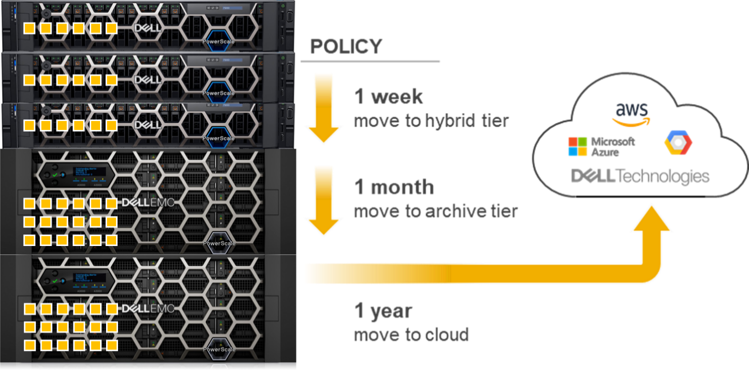
Figure 3. OneFS SmartPools and CloudPools
ONTAP tiers to S3 object stores using FabricPools.
For more information about SmartPools, see Storage Tiering with Dell PowerScale SmartPools. For more information about CloudPools, see:
- Dell PowerScale: CloudPools and Amazon Web Services
- Dell PowerScale: CloudPools and Amazon Web Services
- Dell PowerScale: CloudPools and Alibaba Cloud
- Dell PowerScale: CloudPools and Google Cloud
- Dell PowerScale: CloudPools and ECS
Monitoring
Dell InsightIQ and Dell CloudIQ provide performance monitoring and reporting capabilities. InsightIQ includes advanced analytics to optimize applications, correlate cluster events, and accurately forecast future storage needs. NetApp provides performance monitoring and reporting with Cloud Insights and Active IQ, which are accessible within BlueXP.
For more information about CloudIQ, see CloudIQ: A Detailed Review. For more information about InsightIQ, see InsightIQ on Dell Support.
Security
Similar to ONTAP, the PowerScale OneFS operating system comes with a comprehensive set of integrated security features. These features include data at rest and data in flight encryption, virus scanning tool, WORM SmartLock compliance, external key manager for data at rest encryption, STIG-hardened security profile, Common Criteria certification, and support for UEFI Secure Boot across PowerScale platforms. Further, OneFS may be configured for a Zero Trust architecture and PCI-DSS.
Superna security
Superna exclusively provides the following security-focused applications for PowerScale OneFS:
- Ransomware Defender: Provides real-time event processing through user behavior analytics. The events are used to detect and stop a ransomware attack before it occurs.
- Easy Auditor: Offers a flat-rate license model and ease-of-use features that simplify auditing and securing PBs of data.
- Performance Auditor: Provides real-time file I/O view of PowerScale nodes to simplify root cause of performance impacts, assessing changes needed to optimize performance and debugging user, network, and application performance.
- Airgap: Deployed in two configurations depending on the scale of clusters and security features:
- Basic Airgap Configuration that deploys the Ransomware Defender agent on one of the primary clusters being protected.
- Enterprise Airgap Configuration that deploys the Ransomware Defender agent on the cyber vault cluster. This solution comes with greater scalability and additional security features.
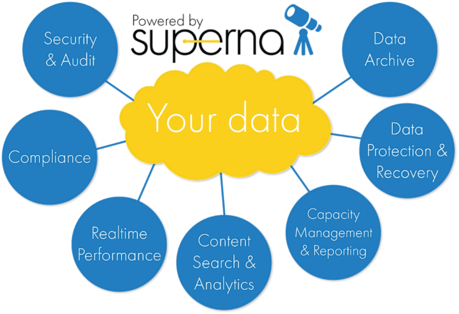
Figure 4. Superna security
NetApp ONTAP security is limited to the integrated features listed above. Additional applications for further security monitoring, like Superna, are not available for ONTAP.
For more information about Superna security, see supernaeyeglass.com. For more information about PowerScale security, see Dell PowerScale OneFS: Security Considerations.
Authentication and access control
NetApp and PowerScale OneFS both support several methods for user authentication and access control. OneFS supports UNIX and Windows permissions for data-level access control. OneFS is designed for a mixed environment that allows the configuration of both Windows Access Control Lists (ACLs) and standard UNIX permissions on the cluster file system. In addition, OneFS provides user and identity mapping, permission mapping, and merging between Windows and UNIX environments.
OneFS supports local and remote authentication providers. Anonymous access is supported for protocols that allow it. Concurrent use of multiple authentication provider types, including Active Directory, LDAP, and NIS, is supported. For example, OneFS is often configured to authenticate Windows clients with Active Directory and to authenticate UNIX clients with LDAP.
Role-based access control
OneFS supports role-based access control (RBAC), allowing administrative tasks to be configured without a root or administrator account. A role is a collection of OneFS privileges that are limited to an area of administration. Custom roles for security, auditing, storage, or backup tasks may be provisioned with RBACs. Privileges are assigned to roles. As users log in to the cluster through the platform API, the OneFS command-line interface, or the OneFS web administration interface, they are granted privileges based on their role membership.
For more information about OneFS authentication and access control, see PowerScale OneFS Authentication, Identity Management, and Authorization.
Learn more about PowerScale OneFS
To learn more about PowerScale OneFS, see the following resources:
- Dell PowerScale Info Hub
- PowerScale OneFS Technical Overview
- Dell PowerScale OneFS Operating System
- OneFS Smartfail blog post
- High Availability and Data Protection with Dell PowerScale Scale-Out NAS
- Dell PowerScale SyncIQ: Architecture, Configuration, and Considerations
- Dell PowerScale: NDMP Technical Overview and Design Considerations
- Storage Quota Management and Provisioning with Dell PowerScale SmartQuotas
- PowerScale: Network Design Considerations
- Dell PowerScale OneFS: Data Reduction and Storage Efficiency
- Next-Generation Storage Efficiency with Dell PowerScale SmartDedupe
- Storage Tiering with Dell PowerScale SmartPools
- Dell PowerScale: CloudPools and Amazon Web Services
- Dell PowerScale: CloudPools and Microsoft Azure
- Dell PowerScale: CloudPools and Alibaba Cloud
- Dell PowerScale: CloudPools and Google Cloud
- Dell PowerScale: CloudPools and ECS
- CloudIQ: A Detailed Review
- InsightIQ (Dell Support page with documentation links)
- Dell PowerScale OneFS: Security Considerations
- PowerScale OneFS Authentication, Identity Management, and Authorization
- Superna website (supernaeyeglass.com)

OneFS SmartQoS Monitoring and Troubleshooting
Tue, 21 Mar 2023 18:30:54 -0000
|Read Time: 0 minutes
The previous articles in this series have covered the SmartQoS architecture, configuration, and management. Now, we’ll turn our attention to monitoring and troubleshooting.
You can use the ‘isi statistics workload’ CLI command to monitor the dataset’s performance. The ‘Ops’ column displays the current protocol operations per second. In the following example, Ops stabilize around 9.8, which is just below the configured limit value of 10 Ops.
# isi statistics workload --dataset ds1 & data
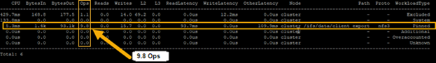
Similarly, this next example from the SmartQoS WebUI shows a small NFS workflow performing 497 protocol Ops in a pinned workload with a limit of 500 Ops:
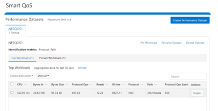
You can pin multiple paths and protocols by selecting the ‘Pin Workload’ option for a given Dataset. Here, four directory path workloads are each configured with different Protocol Ops limits:
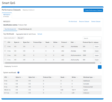
When it comes to troubleshooting SmartQoS, there are a few areas that are worth checking right away, including the SmartQoS Ops limit configuration, isi_pp_d and isi_stats_d daemons, and the protocol service(s).
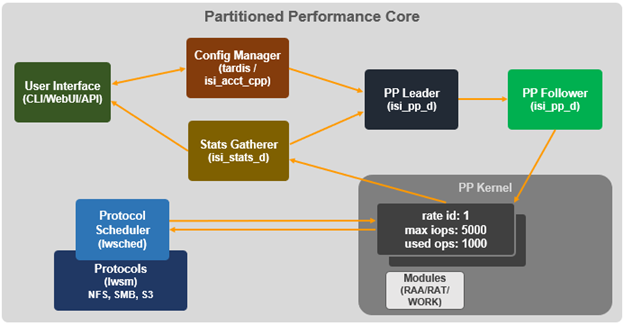
1. For suspected Ops limit configuration issues, first confirm that the SmartQoS limits feature is enabled:
# isi performance settings view
Top N Collections: 1024
Time In Queue Threshold (ms): 10.0
Target read latency in microseconds: 12000.0
Target write latency in microseconds: 12000.0
Protocol Ops Limit Enabled: Yes
Next, verify that the workload level protocols_ops limit is correctly configured:
# isi performance workloads view <workload>
Check whether any errors are reported in the isi_tardis_d configuration log:
# cat /var/log/isi_tardis_d.log
2. To investigate isi_pp_d, first check that the service is enabled:
# isi services –a isi_pp_d
Service 'isi_pp_d' is enabled.
If necessary, you can restart the isi_pp_d service as follows:
# isi services isi_pp_d disable
Service 'isi_pp_d' is disabled.
# isi services isi_pp_d enable
Service 'isi_pp_d' is enabled.
There’s also an isi_pp_d debug tool, which can be helpful in a pinch:
# isi_pp_d -h
Usage: isi_pp_d [-ldhs]
-l Run as a leader process; otherwise, run as a follower. Only one leader process on the cluster will be active.
-d Run in debug mode (do not daemonize).
-s Display pp_leader node (devid and lnn)
-h Display this help.
You can enable debugging on the isi_pp_d log file with the following command syntax:
# isi_ilog -a isi_pp_d -l debug, /var/log/isi_pp_d.log
For example, the following log snippet shows a typical isi_ppd_d.log message communication between isi_pp_d leader and isi_pp_d followers:
/ifs/.ifsvar/modules/pp/comm/SETTINGS
[090500b000000b80,08020000:0000bfddffffffff,09000100:ffbcff7cbb9779de,09000100:d8d2fee9ff9e3bfe,090001 00:0000000075f0dfdf]
100,,,,20,1658854839  < in the format of <workload_id, cputime, disk_reads, disk_writes, protocol_ops, timestamp>
Here, the extract from the /var/log/isi_pp_d.log logfiles from nodes 1 and 2 of a cluster illustrate the different stages of Protocol Ops limit enforcement and usage:
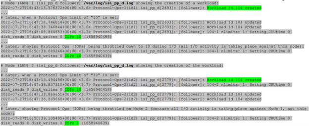
3. To investigate the isi_stats_d, first confirm that the isi_pp_d service is enabled:
# isi services -a isi_stats_d
Service 'isi_stats_d' is enabled.
If necessary, you can restart the isi_stats_d service as follows:
# isi services isi_stats_d disable
# isi services isi_stats_d enable
You can view the workload level statistics with the following command:
# isi statistics workload list --dataset=<name>
You can enable debugging on the isi_stats_d log file with the following command syntax:
# isi_stats_tool --action set_tracelevel --value debug
# cat /var/log/isi_stats_d.log
4. To investigate protocol issues, the ‘isi services’ and ‘lwsm’ CLI commands can be useful. For example, to check the status of the S3 protocol:
# /usr/likewise/bin/lwsm list | grep -i protocol
hdfs                       [protocol]    stopped
lwswift                    [protocol]    running (lwswift: 8393)
nfs                        [protocol]    running (nfs: 8396)
s3                         [protocol]    stopped
srv                        [protocol]    running (lwio: 8096)
# /usr/likewise/bin/lwsm status s3
stopped
# /usr/likewise/bin/lwsm info s3
Service: s3
Description: S3 Server
Categories: protocol
Path: /usr/likewise/lib/lw-svcm/s3.so
Arguments:
Dependencies: lsass onefs_s3 AuditEnabled?flt_audit_s3
Container: s3
This CLI output confirms that the S3 protocol is inactive. You can start the S3 service as follows:
# isi services -a | grep -i s3
s3                   S3
Service                               Enabled
Similarly, you can restart the S3 service as follows:
# /usr/likewise/bin/lwsm restart s3
Stopping service: s3
Starting service: s3
To investigate further, you can increase the protocol’s log level verbosity. For example, to set the s3 log to ‘debug’:
# isi s3 log-level view
Current logging level is 'info'
# isi s3 log-level modify debug
# isi s3 log-level view
Current logging level is 'debug'
Next, view and monitor the appropriate protocol log. For example, for the S3 protocol:
# cat /var/log/s3.log
# tail -f /var/log/s3.log
Beyond the above, you can monitor /var/log/messages for pertinent errors, because the main partition performance (PP) modules log to this file. You can enable debug level logging for the various PP modules as follows.
Dataset:
# sysctl ilog.ifs.acct.raa.syslog=debug+ ilog.ifs.acct.raa.syslog: error,warning,notice (inherited) -> error,warning,notice,info,debug
Workload:
# sysctl ilog.ifs.acct.rat.syslog=debug+ ilog.ifs.acct.rat.syslog: error,warning,notice (inherited) -> error,warning,notice,info,debug
Actor work:
# sysctl ilog.ifs.acct.work.syslog=debug+ ilog.ifs.acct.work.syslog: error,warning,notice (inherited) -> error,warning,notice,info,debug
When finished, you can restore the default logging levels for the above modules as follows:
# sysctl ilog.ifs.acct.raa.syslog=notice+ # sysctl ilog.ifs.acct.rat.syslog=notice+ # sysctl ilog.ifs.acct.work.syslog=notice+
Author: Nick Trimbee

OneFS SmartQoS Configuration and Setup
Tue, 14 Mar 2023 16:06:06 -0000
|Read Time: 0 minutes
In the previous article in this series, we looked at the underlying architecture and management of SmartQoS in OneFS 9.5. Next, we’ll step through an example SmartQoS configuration using the CLI and WebUI.
After an initial set up, configuring a SmartQoS protocol Ops limit comprises four fundamental steps. These are:

Step | Task | Description | Example |
1 | Identify Metrics of interest | Used for tracking, to enforce an Ops limit | Uses ‘path’ and ‘protocol’ for the metrics to identify the workload. |
2 | Create a Dataset | For tracking all of the chosen metric categories | Create the dataset ‘ds1’ with the metrics identified. |
3 | Pin a Workload | To specify exactly which values to track within the chosen metrics | path: /ifs/data/client_exports protocol: nfs3 |
4 | Set a Limit | To limit Ops based on the dataset, metrics (categories), and metric values defined by the workload | Protocol_ops limit: 100 |
Step 1:

First, select a metric of interest. For this example, we’ll use the following:
- Protocol: NFSv3
- Path: /ifs/test/expt_nfs
If not already present, create and verify an NFS export – in this case at /ifs/test/expt_nfs:
# isi nfs exports create /ifs/test/expt_nfs # isi nfs exports list ID Zone Paths Description ------------------------------------------------ 1 System /ifs/test/expt_nfs ------------------------------------------------
Or from the WebUI, under Protocols UNIX sharing (NFS) > NFS exports:
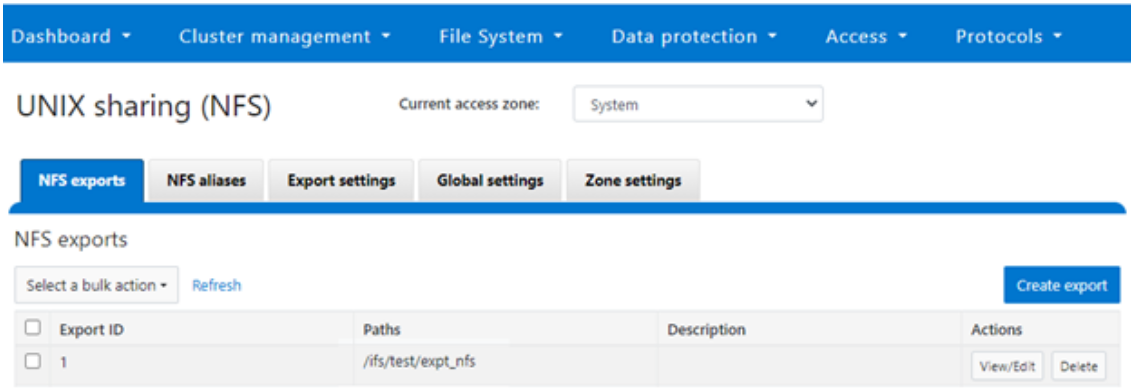
Step 2:

The ‘dataset’ designation is used to categorize workload by various identification metrics, including:
ID Metric | Details |
Username | UID or SID |
Primary groupname | Primary GID or GSID |
Secondary groupname | Secondary GID or GSID |
Zone name |
|
IP address | Local or remote IP address or IP address range |
Path | Except for S3 protocol |
Share | SMB share or NFS export ID |
Protocol | NFSv3, NFSv4, NFSoRDMA, SMB, or S3 |
SmartQoS in OneFS 9.5 only allows protocol Ops as the transient resources used for configuring a limit ceiling.
For example, you can use the following CLI command to create a dataset ‘ds1’, specifying protocol and path as the ID metrics:
# isi performance datasets create --name ds1 protocol path Created new performance dataset 'ds1' with ID number 1.
Note: Resource usage tracking by the ‘path’ metric is only supported by SMB and NFS.
The following command displays any configured datasets:
# isi performance datasets list
Or, from the WebUI, by navigating to Cluster management > Smart QoS:
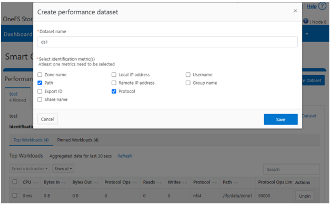
Step 3:

After you have created the dataset, you can pin a workload to it by specifying the metric values. For example:
# isi performance workloads pin ds1 protocol:nfs3 path: /ifs/test/expt_nfs
Pinned performance dataset workload with ID number 100.
Or from the WebUI, by browsing to Cluster management > Smart QoS > Pin workload:
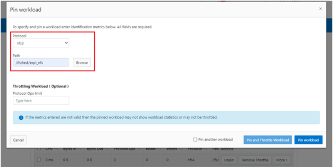
After pinning a workload, the entry appears in the ‘Top Workloads’ section of the WebUI page. However, wait at least 30 seconds to start receiving updates.
To list all the pinned workloads from a specified dataset, use the following command:
# isi performance workloads list ds1
The prior command’s output indicates that there are currently no limits set for this workload.
By default, a protocol ops limit exists for each workload. However, it is set to the maximum (the maximum value of a 64-bit unsigned integer). This is represented in the CLI output by a dash (“-“) if a limit has not been explicitly configured:
# isi performance workloads list ds1 ID Name Metric Values Creation Time Cluster Resource Impact Client Impact Limits -------------------------------------------------------------------------------------- 100 - path:/ifs/test/expt_nfs 2023-02-02T12:06:05 - - - protocol:nfs3 -------------------------------------------------------------------------------------- Total: 1
Step 4:

For a pinned workload in a dataset, you can configure a limit for the protocol ops limit from the CLI, using the following syntax:
# isi performance workloads modify <dataset> <workload ID> --limits protocol_ops:<value>
When configuring SmartQoS, always be aware that it is a powerful performance throttling tool which can be applied to significant areas of a cluster’s data and userbase. For example, protocol Ops limits can be configured for metrics such as ‘path:/ifs’, which would affect the entire /ifs filesystem, or ‘zone_name:System’ which would limit the System access zone and all users within it. While such configurations are entirely valid, they would have a significant, system-wide impact. As such, exercise caution when configuring SmartQoS to avoid any inadvertent, unintended, or unexpected performance constraints.
In the following example, the dataset is ‘ds1’, the workload ID is ‘100’, and the protocol Ops limit is set to the value ‘10’:
# isi performance workloads modify ds1 100 --limits protocol_ops:10 protocol_ops: 18446744073709551615 -> 10
Or from the WebUI, by browsing to Cluster management > Smart QoS > Pin and throttle workload:
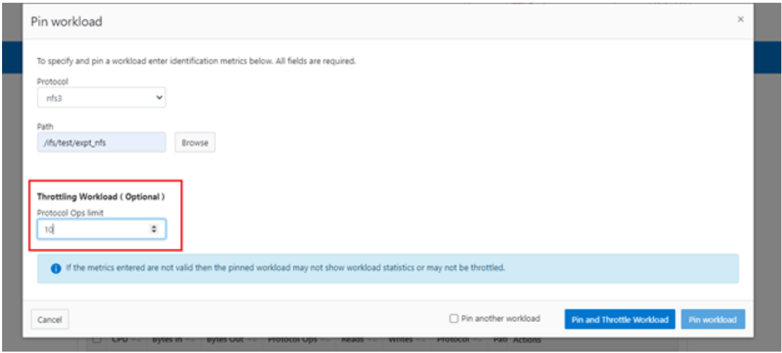
You can use the ‘isi performance workloads’ command in ‘list’ mode to show details of the workload ‘ds1’. In this case, ‘Limits’ is set to protocol_ops = 10.
# isi performance workloads list test ID Name Metric Values Creation Time Cluster Resource Impact Client Impact Limits -------------------------------------------------------------------------------------- 100 - path:/ifs/test/expt_nfs 2023-02-02T12:06:05 - - protocol_ops:10 protocol:nfs3 -------------------------------------------------------------------------------------- Total: 1
Or in ‘view’ mode:
# isi performance workloads view ds1 100 ID: 100 Name: - Metric Values: path:/ifs/test/expt_nfs, protocol:nfs3 Creation Time: 2023-02-02T12:06:05 Cluster Resource Impact: - Client Impact: - Limits: protocol_ops:10
Or from the WebUI, by browsing to Cluster management > Smart QoS:

You can easily modify the limit value of a pinned workload with the following CLI syntax. For example, to set the limit to 100 Ops:
# isi performance workloads modify ds1 100 --limits protocol_ops:100
Or from the WebUI, by browsing to Cluster management > Smart QoS > Edit throttle:
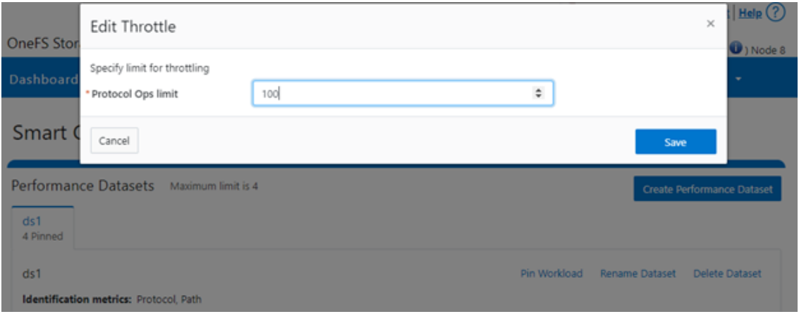
Similarly, you can use the following CLI command to easily remove a protocol ops limit for a pinned workload:
# isi performance workloads modify ds1 100 --no-protocol-ops-limit
Or from the WebUI, by browsing to Cluster management > Smart QoS > Remove throttle:
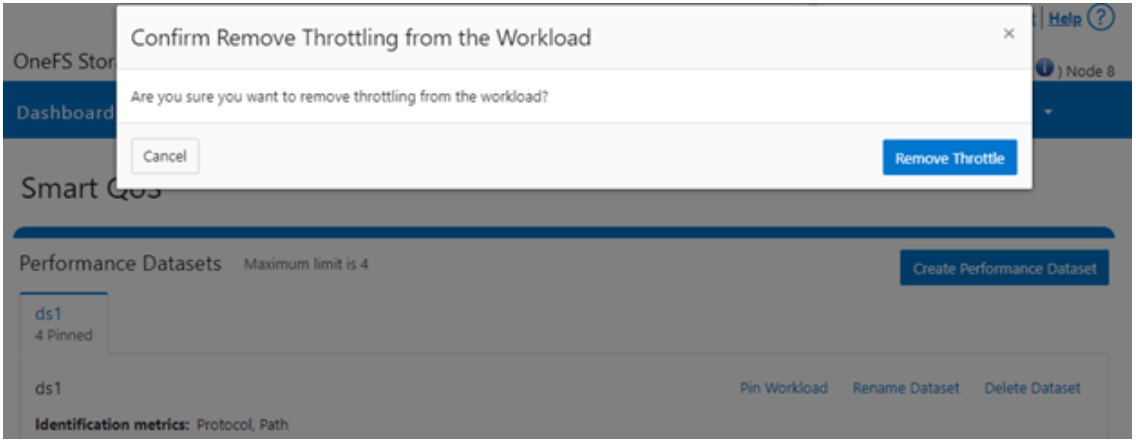
Author: Nick Trimbee

OneFS SupportAssist
Mon, 13 Mar 2023 23:31:33 -0000
|Read Time: 0 minutes
Among the myriad of new features included in the OneFS 9.5 release is SupportAssist, Dell’s next-gen remote connectivity system. SupportAssist is included with all support plans (features vary based on service level agreement).
Dell SupportAssist rapidly identifies, diagnoses, and resolves cluster issues and provides the following key benefits:
- Improves productivity by replacing manual routines with automated support
- Accelerates resolution, or avoid issues completely, with predictive issue detection and proactive remediation
Within OneFS, SupportAssist transmits events, logs, and telemetry from PowerScale to Dell support. As such, it provides a full replacement for the legacy ESRS.
Delivering a consistent remote support experience across the Dell storage portfolio, SupportAssist is intended for all sites that can send telemetry off-cluster to Dell over the Internet. SupportAssist integrates the Dell Embedded Service Enabler (ESE) into PowerScale OneFS along with a suite of daemons to allow its use on a distributed system.
| SupportAssist | ESRS |
|---|---|
Dell’s next-generation remote connectivity solution | Being phased out of service |
Can either connect directly, or through supporting gateways | Can only use gateways for remote connectivity |
Uses Connectivity Hub to coordinate support | Uses ServiceLink to coordinate support |
Using the Dell Connectivity Hub, SupportAssist can either interact directly or through a Secure Connect gateway.
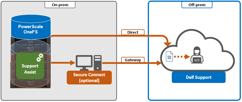
SupportAssist has a variety of components that gather and transmit various pieces of OneFS data and telemetry to Dell Support and backend services through the Embedded Service Enabler (ESE). These workflows include CELOG events; In-product activation (IPA) information; CloudIQ telemetry data; Isi-Gather-info (IGI) logsets; and provisioning, configuration, and authentication data to ESE and the various backend services.
| Workflow | Details |
|---|---|
CELOG | In OneFS 9.5, SupportAssist can be configured to send CELOG events and attachments through ESE to CLM. CELOG has a “supportassist” channel that, when active, creates an EVENT task for SupportAssist to propagate. |
License Activation | The isi license activation start command uses SupportAssist to connect.
Several pieces of PowerScale and OneFS functionality require licenses, and must communicate with the Dell backend services in order to register and activate those cluster licenses. In OneFS 9.5, SupportAssist is the preferred mechanism to send those license activations through ESE to the Dell backend. License information can be generated through the isi license generate CLI command and then activated with the isi license activation start syntax. |
Provisioning | SupportAssist must register with backend services in a process known as provisioning. This process must be run before the ESE will respond on any of its other available API endpoints. Provisioning can only successfully occur once per installation, and subsequent provisioning tasks will fail. SupportAssist must be configured through the CLI or WebUI before provisioning. The provisioning process uses authentication information that was stored in the key manager upon the first boot. |
Diagnostics | The OneFS isi diagnostics gather and isi_gather_info logfile collation and transmission commands have a --supportassist option. |
Healthchecks | HealthCheck definitions are updated using SupportAssist. |
Telemetry | CloudIQ telemetry data is sent using SupportAssist. |
Remote Support | Remote Support uses SupportAssist and the Connectivity Hub to assist customers with their clusters. |
SupportAssist requires an access key and PIN, or hardware key, to be enabled, with most customers likely using the access key and pin method. Secure keys are held in key manager under the RICE domain.
In addition to the transmission of data from the cluster to Dell, Connectivity Hub also allows inbound remote support sessions to be established for remote cluster troubleshooting.
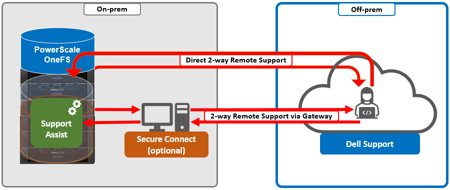
In the next article in this series, we’ll take a deeper look at the SupportAssist architecture and operation.

OneFS SmartQoS Architecture and Management
Wed, 01 Mar 2023 22:34:30 -0000
|Read Time: 0 minutes
The SmartQoS Protocol Ops limits architecture, introduced in OneFS 9.5, involves three primary capabilities:
- Resource tracking
- Resource limit distribution
- Throttling
Under the hood, the OneFS protocol heads (NFS, SMB, and S3) identify and track how many protocol operations are being processed through a specific export or share. The existing partitioned performance (PP) reporting infrastructure is leveraged for cluster wide resource usage collection, limit calculation and distribution, along with new OneFS 9.5 functionality to support pinned workload protocol Ops limits.
The protocol scheduling module (LwSched) has a built-in throttling capability that allows the execution of individual operations to be delayed by temporarily pausing them, or ‘sleeping’. Additionally, in OneFS 9.5, the partitioned performance kernel modules have also been enhanced to calculate ‘sleep time’ based on operation count resource information (requested, average usage, and so on) – both within the current throttling window, and for a specific workload.
We can characterize the fundamental SmartQoS workflow as follows:
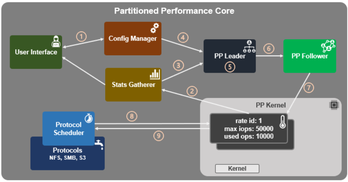
- Configuration, using the CLI, pAPI, or WebUI.
- Statistics gatherer obtains Op/s data from the partitioned performance (PP) kernel.
- Stats gatherer communicates Op/s data to PP leader service.
- Leader queries config manager for per-cluster rate limit.
- Leader calculates per-node limit.
- PP follower service is notified of per-node Op/s limit.
- Kernel is informed of new per-node limit.
- Work is scheduled with rate-limited resource.
- Kernel returns sleep time, if needed.
When an admin configures a per-cluster protocol Ops limit, the statistics gathering service, isi_stats_d, begins collecting workload resource information every 30 seconds by default from the partitioned performance (PP) kernel on each node in the cluster and notifies the isi_pp_d leader service of this resource info. Next, the leader gets the per-cluster protocol Ops limit plus additional resource consumption metrics from the isi_acct_cpp service from isi_tardis_d, the OneFS cluster configuration service and calculates the protocol Ops limit of each node for the next throttling window. It then instructs the isi_pp_d follower service on each node to update the kernel with the newly calculated protocol Ops limit, plus a request to reset the throttling window.
When the kernel receives a scheduling request for a work item from the protocol scheduler (LwSched), the kernel calculates the required ‘sleep time’ value, based on the current node protocol Ops limit and resource usage in the current throttling window. If insufficient resources are available, the work item execution thread is put to sleep for a specific interval returned from the PP kernel. If resources are available, or the thread is reactivated from sleeping, it executes the work item and reports the resource usage statistics back to PP, releasing any scheduling resources it may own.
SmartQoS can be configured through either the CLI, platform API, or WebUI, and OneFS 9.5 introduces a new SmartQoS WebUI page to support this. Note that SmartQoS is only available when an upgrade to OneFS 9.5 has been committed, and any attempt to configure or run the feature prior to upgrade commit will fail with the following message:
# isi performance workloads modify DS1 -w WS1 --limits protocol_ops:50000 Setting of protocol ops limits not available until upgrade has been committed
When a cluster is running OneFS 9.5 and the release is committed, the SmartQoS feature is enabled by default. This, and the current configuration, can be confirmed using the following CLI command:
# isi performance settings view Top N Collections: 1024 Time In Queue Threshold (ms): 10.0 Target read latency in microseconds: 12000.0 Target write latency in microseconds: 12000.0 Protocol Ops Limit Enabled: Yes
In OneFS 9.5, the ‘isi performance settings modify’ CLI command now includes a ‘protocol-ops-limit-enabled’ parameter to allow the feature to be easily disabled (or re-enabled) across the cluster. For example:
# isi performance settings modify --protocol-ops-limit-enabled false protocol_ops_limit_enabled: True -> False
Similarly, the ‘isi performance settings view’ CLI command has been extended to report the protocol OPs limit state:
# isi performance settings view * Top N Collections: 1024 Protocol Ops Limit Enabled: Yes
In order to set a protocol OPs limit on workload from the CLI, the ‘isi performance workload pin’ and ‘isi performance workload modify’ commands now accept an optional ‘–limits’ parameter. For example, to create a pinned workload with the ‘protocol_ops’ limit set to 10000:
# isi performance workload pin test protocol:nfs3 --limits protocol_ops:10000
Similarly, to modify an existing workload’s ‘protocol_ops’ limit to 20000:
# isi performance workload modify test 101 --limits protocol_ops:20000 protocol_ops: 10000 -> 20000
When configuring SmartQoS, always be aware that it is a powerful throttling tool that can be applied to significant areas of a cluster’s data and userbase. For example, protocol OPs limits can be configured for metrics such as ‘path:/ifs’, which would affect the entire /ifs filesystem, or ‘zone_name:System’ which would limit the System access zone and all users within it.
While such configurations are entirely valid, they would have a significant, system-wide impact. As such, exercise caution when configuring SmartQoS to avoid any inadvertent, unintended, or unexpected performance constraints.
To clear a protocol Ops limit on workload, the ‘isi performance workload modify’ CLI command has been extended to accept an optional ‘–noprotocol-ops-limit’ argument. For example:
# isi performance workload modify test 101 --no-protocol-ops-limit protocol_ops: 20000 -> 18446744073709551615
Note that the value of ‘18446744073709551615’ in the command output above represents ‘NO_LIMIT’ set.
You can view a workload’s protocol Ops limit by using the ‘isi performance workload list’ and ‘isi performance workload view’ CLI commands, which have been modified in OneFS 9.5 to display the limits appropriately. For example:
# isi performance workload list test ID Name Metric Values Creation Time Impact Limits --------------------------------------------------------------------- 101 - protocol:nfs3 2023-02-02T22:35:02 - protocol_ops:20000 --------------------------------------------------------------------- # isi performance workload view test 101 ID: 101 Name: - Metric Values: protocol:nfs3 Creation Time: 2023-02-02T22:35:02 Impact: - Limits: protocol_ops:20000
In the next article in this series, we’ll step through an example SmartQoS configuration and verification from both the CLI and WebUI.
Author: Nick Trimbee

OneFS SmartQoS
Thu, 23 Feb 2023 22:34:49 -0000
|Read Time: 0 minutes
Built atop the partitioned performance (PP) resource monitoring framework, OneFS 9.5 introduces a new SmartQoS performance management feature. SmartQoS allows a cluster administrator to set limits on the maximum number of protocol operations per second (Protocol Ops) that individual pinned workloads can consume, in order to achieve desired business workload prioritization. Among the benefits of this new QoS functionality are:
- Enabling IT infrastructure teams to achieve performance SLAs
- Allowing throttling of rogue or low priority workloads and hence prioritization of other business critical workloads
- Helping minimize data unavailability events due to overloaded clusters
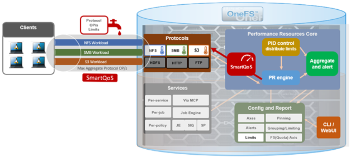
This new SmartQoS feature in OneFS 9.5 supports the NFS, SMB and S3 protocols, including mixed traffic to the same workload.
But first, a quick refresher. The partitioned performance resource monitoring framework, which initially debuted in OneFS 8.0.1, enables OneFS to track and report the use of transient system resources (resources that only exist at a given instant), providing insight into who is consuming what resources, and how much of them. Examples include CPU time, network bandwidth, IOPS, disk accesses, and cache hits, and so on.
OneFS partitioned performance is an ongoing project that in OneFS 9.5 now provides control and insights. This allows control of work flowing through the system, prioritization and protection of mission critical workflows, and the ability to detect if a cluster is at capacity.
Because identification of work is highly subjective, OneFS partitioned performance resource monitoring provides significant configuration flexibility, by allowing cluster admins to craft exactly how they want to define, track, and manage workloads. For example, an administrator might want to partition their work based on criteria such as which user is accessing the cluster, the export/share they are using, which IP address they’re coming from – and often a combination of all three.
OneFS has always provided client and protocol statistics, but they were typically front-end only. Similarly, OneFS has provided CPU, cache, and disk statistics, but they did not display who was consuming them. Partitioned performance unites these two realms, tracking the usage of the CPU, drives, and caches, and spanning the initiator/participant barrier.
OneFS collects the resources consumed and groups them into distinct workloads. The aggregation of these workloads comprises a performance dataset.
Item | Description | Example |
Workload | A set of identification metrics and resources used | {username:nick, zone_name:System} consumed {cpu:1.5s, bytes_in:100K, bytes_out:50M, …} |
Performance Dataset | The set of identification metrics by which to aggregate workloads
The list of workloads collected that match that specification | {usernames, zone_names} |
Filter | A method for including only workloads that match specific identification metrics |
|
The following metrics are tracked by partitioned performance resource monitoring:
Category | Items |
Identification Metrics |
|
Transient Resources |
|
Performance Statistics |
|
Supported Protocols |
|
Be aware that, in OneFS 9.5, SmartQoS currently does not support the following Partitioned Performance criteria:
Unsupported Group | Unsupported Items |
Metrics |
|
Workloads |
|
Protocols |
|
When pinning a workload to a dataset, note that the more metrics there are in that dataset, the more parameters need to be defined when pinning to it. For example:
Dataset = zone_name, protocol, username
To set a limit on this dataset, you’d need to pin the workload by also specifying the zone name, protocol, and username.
When using the remote_address and/or local_address metrics, you can also specify a subnet. For example: 10.123.456.0/24
With the exception of the system dataset, you must configure performance datasets before statistics are collected.
For SmartQoS in OneFS 9.5, you can define and configure limits as a maximum number of protocol operations (Protocol Ops) per second across the following protocols:
- NFSv3
- NFSv4
- NFSoRDMA
- SMB
- S3
You can apply a Protocol Ops limit to up to four custom datasets. All pinned workloads within a dataset can have a limit configured, up to a maximum of 1024 workloads per dataset. If multiple workloads happen to share a common metric value with overlapping limits, the lowest limit that is configured would be enforced
Note that when upgrading to OneFS 9.5, SmartQoS is activated only when the new release has been successfully committed.
In the next article in this series, we’ll take a deeper look at SmartQoS’ underlying architecture and workflow.
Author: Nick Trimbee

OneFS SmartPools Transfer Limits Configuration and Management
Thu, 16 Feb 2023 15:48:08 -0000
|Read Time: 0 minutes
In the first article in this series, we looked at the architecture and considerations of the new SmartPools transfer limits in OneFS 9.5. Now, we turn our attention to the configuration and management of this feature.
From the control plane side, OneFS 9.5 contains several WebUI and CLI enhancements to reflect the new SmartPools transfer limits functionality. Probably the most obvious change is in the Local storage usage status histogram, where tiers and their child node pools have been aggregated for a more logical grouping. Also, blue limit-lines have been added above each of the storage pools, and a red warning status is displayed for any pools that have exceeded the transfer limit.
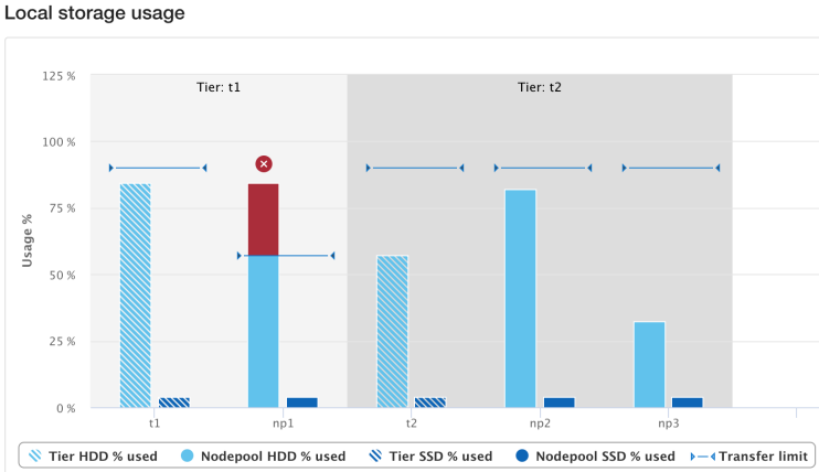
Similarly, the storage pools status page now includes transfer limit details, with the 90% limit displayed for any storage pools using the default setting.
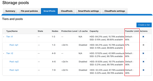
From the CLI, the isi storagepool nodepools view command reports the transfer limit status and percentage for a pool. The used SSD and HDD bytes percentages in the command output indicate where the pool utilization is relative to the transfer limit.
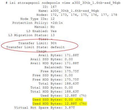
The storage transfer limit can be easily configured from the CLI as either for a specific pool, as a default, or disabled, using the new –transfer-limit and –default-transfer-limit flags.
The following CLI command can be used to set the transfer limit for a specific storage pool:
# isi storagepool nodepools/tier modify --transfer-limit={0-100, default, disabled} For example, to set a limit of 80% on an A200 nodepool:
# isi storagepool a200_30tb_1.6tb-ssd_96gb modify --transfer-limit=80
Or to set the default limit of 90% on tier perf1:
# isi storagepool perf1 --transfer-limit=default
Note that setting the transfer limit of a tier automatically applies to all its child node pools, regardless of any prior child limit configurations.
The global isi storage settings view CLI command output shows the default transfer limit, which is 90%, but it can be configured between 0 to 100%.
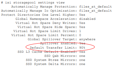
This default limit can be reconfigured from the CLI with the following syntax:
# isi storagepool settings modify --default-transfer-limit={0-100, disabled}For example, to set a new default transfer limit of 85%:
# isi storagepool settings modify --default-transfer-limit=85
And the same changes can be made from the SmartPools WebUI, by navigating to Storage pools > SmartPools settings:
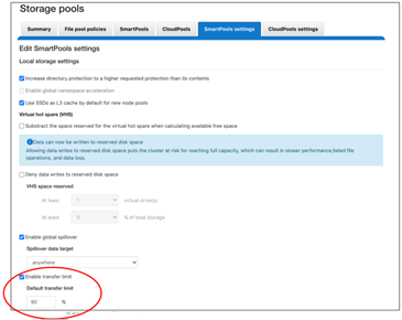
Once a SmartPools job has been completed in OneFS 9.5, the job report contains a new field, files not moved due to transfer limit exceeded.
# isi job reports view 1056 ... ... Policy/testpolicy/Access changes skipped 0 Policy/testpolicy/ADS containers matched 'head’ 0 Policy/testpolicy/ADS containers matched 'snapshot’ 0 Policy/testpolicy/ADS streams matched 'head’ 0 Policy/testpolicy/ADS streams matched 'snapshot’ 0 Policy/testpolicy/Directories matched 'head’ 0 Policy/testpolicy/Directories matched 'snapshot’ 0 Policy/testpolicy/File creation templates matched 0 Policy/testpolicy/Files matched 'head’ 0 Policy/testpolicy/Files matched 'snapshot’ 0 Policy/testpolicy/Files not moved due to transfer limit exceeded 0 Policy/testpolicy/Files packed 0 Policy/testpolicy/Files repacked 0 Policy/testpolicy/Files unpacked 0 Policy/testpolicy/Packing changes skipped 0 Policy/testpolicy/Protection changes skipped 0 Policy/testpolicy/Skipped files already in containers 0 Policy/testpolicy/Skipped packing non-regular files 0 Policy/testpolicy/Skipped packing regular files 0
Additionally, the SYS STORAGEPOOL FILL LIMIT EXCEEDED alert is triggered at the Info level when a storage pool’s usage has exceeded its transfer limit. Each hour, CELOG fires off a monitor helper script that measures how full each storage pool is relative to its transfer limit. The usage is gathered by reading from the disk pool database, and the transfer limits are stored in gconfig. If a node pool has a transfer limit of 50% and usage of 75%, the monitor helper would report a measurement of 150%, triggering an alert.
# isi event view 126 ID: 126 Started: 11/29 20:32 Causes Long: storagepool: vonefs_13gb_4.2gb-ssd_6gb:hdd usage: 33.4, transfer limit: 30.0 Lnn: 0 Devid: 0 Last Event: 2022-11-29T20:32:16 Ignore: No Ignore Time: Never Resolved: No Resolve Time: Never Ended: -- Events: 1 Severity: information
And from the WebUI:
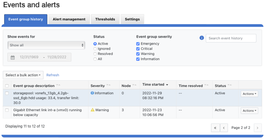
And there you have it: Transfer limits, and the first step in the evolution toward a smarter SmartPools.

OneFS SmartPools Transfer Limits
Wed, 15 Feb 2023 22:53:09 -0000
|Read Time: 0 minutes
The new OneFS 9.5 release introduces the first phase of engineering’s Smarter SmartPools initiative, and delivers a new feature called SmartPools transfer limits.
The goal of SmartPools Transfer Limits is to address spill over. Previously, when file pool policies were executed, OneFS had no guardrails to protect against overfilling the destination or target storage pool. So if a pool was overfilled, data would unexpectedly spill over into other storage pools.
An overflow would result in storagepool usage exceeding 100%, and cause the SmartPools job itself to do a considerable amount of unnecessary work, trying to send files to a given storagepool. But because the pool was full, it would then have to send those files off to another storage pool that was below capacity. This would result in data going where it wasn’t intended, and the potential for individual files to end up getting split between pools. Also, if the full pool was on the most highly performing storage in the cluster, all subsequent newly created data would now land on slower storage, affecting its throughput and latency. The recovery from a spillover can be fairly cumbersome because it’s tough for the cluster to regain balance, and urgent system administration may be required to free space on the affected tier.
In order to address this, SmartPools Transfer Limits allows a cluster admin to configure a storagepool capacity-usage threshold, expressed as a percentage, and beyond which file pool policies stop moving data to that particular storage pool.
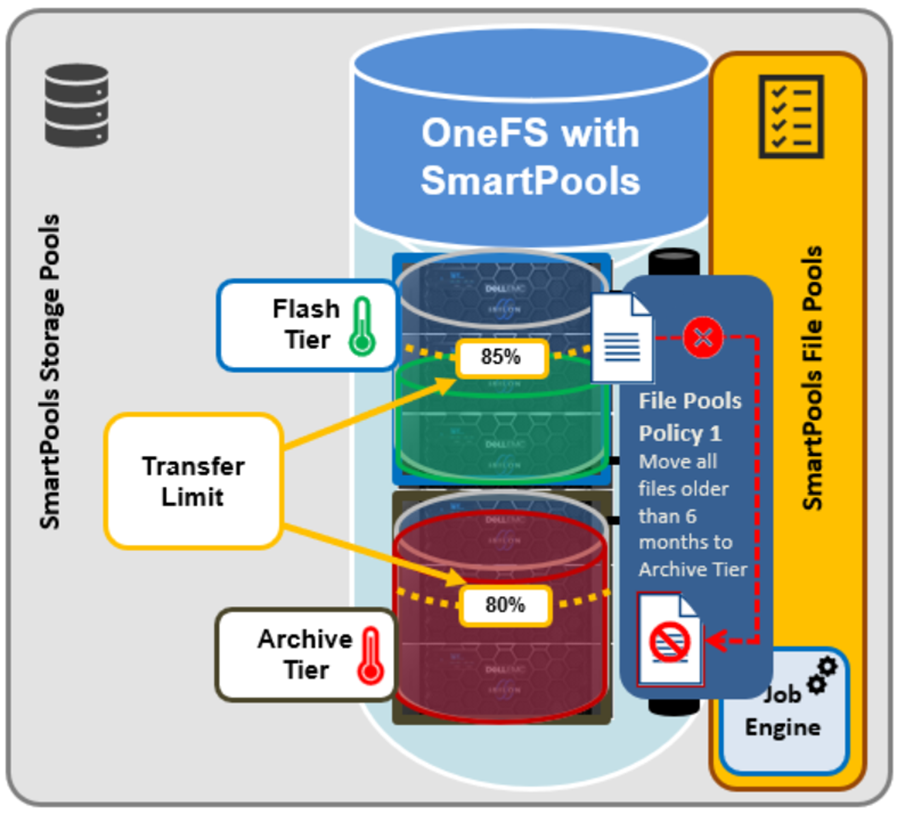
These transfer limits only take effect when running jobs that apply filepool policies, such as SmartPools, SmartPoolsTree, and FilePolicy.
The main benefits of this feature are two-fold:
- Safety, in that OneFS avoids undesirable actions, so the customer is prevented from getting into escalation situations, because SmartPools won’t overfill storage pools.
- Performance, because transfer limits avoid unnecessary work, and allow the SmartPools job to finish sooner.
Under the hood, a cluster’s storagepool SSD and HDD usage is calculated using the same algorithm as reported by the ‘isi storagepools list’ CLI command. This means that a pool’s VHS (virtual hot spare) reserved capacity is respected by SmartPools transfer limits. When a SmartPools job is running, there is at least one worker on each node processing a single LIN at any given time. In order to calculate the current HDD and SSD usage per storagepool, the worker must read from the diskpool database. To circumvent this potential bottleneck, the filepool policy algorithm caches the diskpool database contents in memory for up to 10 seconds.
Transfer limits are stored in gconfig, and a separate entry is stored within the ‘smartpools.storagepools’ hierarchy for each explicitly defined transfer limit.
Note that in the SmartPools lexicon, ‘storage pool’ is a generic term denoting either a tier or nodepool. Additionally, SmartPools tiers comprise one or more constituent nodepools.
Each gconfig transfer limit entry stores a limit value and the diskpool database identifier of the storagepool to which the transfer limit applies. Additionally, a ‘transfer limit state’ field specifies which of three states the limit is in:
Limit state | Description |
Default | Fallback to the default transfer limit. |
Disabled | Ignore transfer limit. |
Enabled | The corresponding transfer limit value is valid. |
A SmartPools transfer limit does not affect the general ingress, restriping, or reprotection of files, regardless of how full the storage pool is where that file is located. So if you’re creating or modifying a file on the cluster, it will be created there anyway. This will continue up until the pool reaches 100% capacity, at which point it will then spill over.
The default transfer limit is 90% of a pool’s capacity. This applies to all storage pools where the cluster admin hasn’t explicitly set a threshold. Note also that the default limit doesn’t get set until a cluster upgrade to OneFS 9.5 has been committed. So if you’re running a SmartPools policy job during an upgrade, you’ll have the preexisting behavior, which is to send the file to wherever the file pool policy instructs it to go. It’s also worth noting that, even though the default transfer limit is set on commit, if a job was running over that commit edge, you’d have to pause and resume it for the new limit behavior to take effect. This is because the new configuration is loaded lazily when the job workers are started up, so even though the configuration changes, a pause and resume is needed to pick up those changes.
SmartPools itself needs to be licensed on a cluster in order for transfer limits to work. And limits can be configured at the tier or nodepool level. But if you change the limit of a tier, it automatically applies to all of its child nodepools, regardless of any prior child limit configurations. The transfer limit feature can also be disabled, which results in the same spillover behavior OneFS always displayed, and any configured limits will not be respected.
Note that a filepool policy’s transfer limits algorithm does not consider the size of the file when deciding whether to move it to the policy’s target storagepool, regardless of whether the file is empty, or a large file. Similarly, a target storagepool’s usage must exceed its transfer limit before the filepool policy will stop moving data to that target pool. The assumption here is that any storagepool usage overshoot is insignificant in scale compared to the capacity of a cluster’s storagepool.
A SmartPools file pool policy allows you to send snapshot or HEAD data blocks to different targets, if so desired.
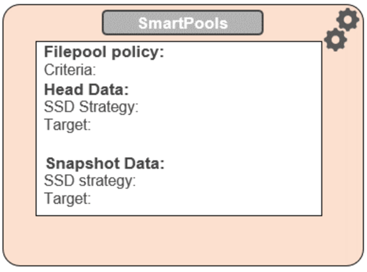
Because the transfer limit applies to the storagepool itself, and not to the file pool policy, it’s important to note that, if you’ve got varying storagepool targets and one file pool policy, you may have a situation where the head data blocks do get moved. But if the snapshot is pointing at a storage pool that has exceeded its transfer limit, its blocks will not be moved.
File pool policies also allow you to specify how a mixed node’s SSDs are used: either as L3 cache, or as an SSD strategy for head and snapshot blocks. If the SSDs in a node are configured for L3, they are not being used for storage, so any transfer limits are irrelevant to it. As an alternative to L3 cache, SmartPools offers three main categories of SSD strategy:
- Avoid, which means send all blocks to HDD
- Data, which means send everything to SSD
- Metadata Read or Write, which sends varying numbers of metadata mirrors to SSD, and data blocks to hard disk.
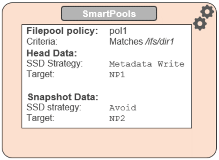
To reflect this, SmartPools transfer limits are slightly nuanced when it comes to SSD strategies. That is, if the storagepool target contains both HDD and SSD, the usage capacity of both mediums needs to be below the transfer limit in order for the file to be moved to that target. For example, take two node pools, NP1 and NP2.
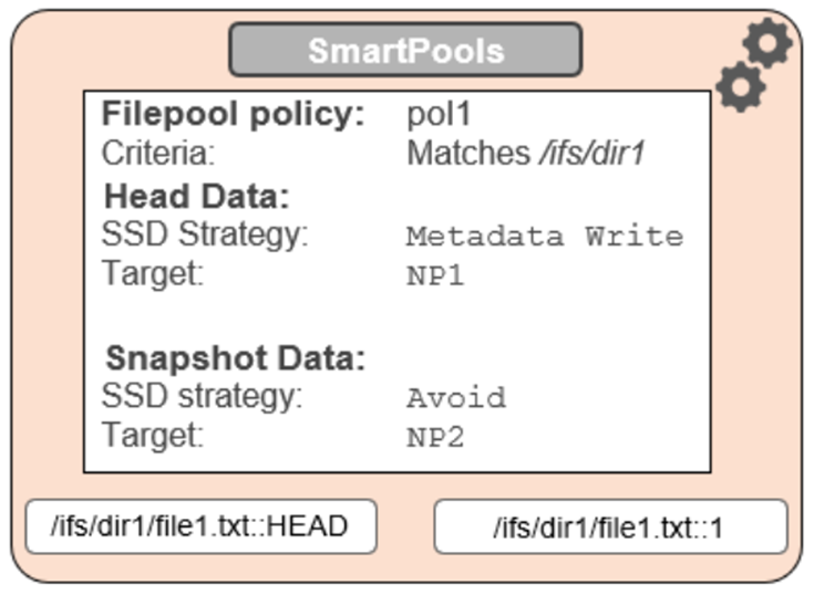
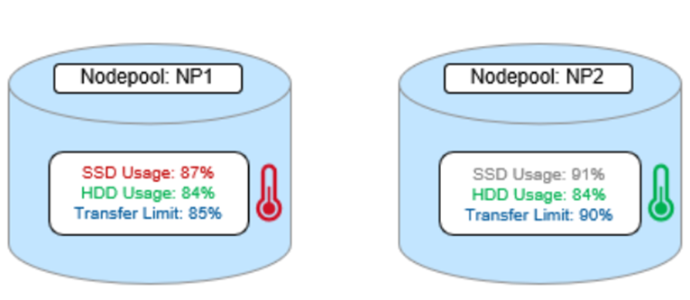
A file pool policy, Pol1, is configured and which matches all files under /ifs/dir1, with an SSD strategy of Metadata Write, and pool NP1 as the target for HEAD’s data blocks. For snapshots, the target is NP2, with an ‘avoid’ SSD strategy, so just writing to hard disk for both snapshot data and metadata.
When a SmartPools job runs and attempts to apply this file pool policy, it sees that SSD usage is above the 85% configured transfer limit for NP1. So, even though the hard disk capacity usage is below the limit, neither HEAD data nor metadata will be sent to NP1.
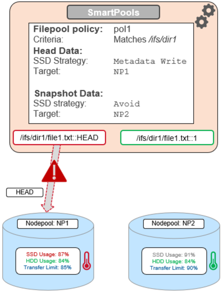
For the snapshot, the SSD usage is also above the NP2 pool’s transfer limit of 90%.
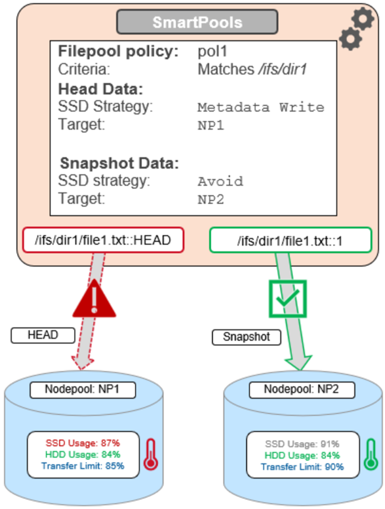
However, because the SSD strategy is ‘avoid’, and because the hard disk usage is below the limit, the snapshot’s data and metadata get successfully sent to the NP2 HDDs.
Author: Nick Trimbee

PowerScale OneFS 9.5 Delivers New Security Features and Performance Gains
Fri, 28 Apr 2023 19:57:51 -0000
|Read Time: 0 minutes
PowerScale – the world’s most flexible[1] and cyber-secure scale-out NAS solution[2] – is powering up the new year with the launch of the innovative OneFS 9.5 release. With data integrity and protection being top of mind in this era of unprecedented corporate cyber threats, OneFS 9.5 brings an array of new security features and functionality to keep your unstructured data and workloads more secure than ever, as well as delivering significant performance gains on the PowerScale nodes – such as up to 55% higher performance on all-flash F600 and F900 nodes as compared with the previous OneFS release.[3]
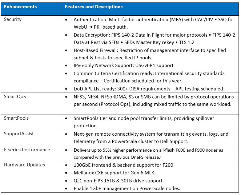
OneFS and hardware security features
New PowerScale OneFS 9.5 security enhancements include those that directly satisfy US Federal and DoD mandates, such as FIPS 140-2, Common Criteria, and DISA STIGs – in addition to general enterprise data security requirements. Multi-factor authentication (MFA), single sign-on (SSO) support, data encryption in-flight and at rest, TLS 1.2, USGv6R1 IPv6 support, SED Master Key rekey, plus a new host-based firewall are all part of OneFS 9.5.
15TB and 30TB self-encrypting (SED) SSDs now enable PowerScale platforms running OneFS 9.5 to scale up to 186 PB of encrypted raw capacity per cluster – all within a single volume and filesystem, and before any additional compression and deduplication benefit.
Delivering federal-grade security to protect data under a zero trust model
Security-wise, the United States Government has stringent requirements for infrastructure providers such as Dell Technologies, requiring vendors to certify that products comply with requirements such as USGv6, STIGs, DoDIN APL, Common Criteria, and so on. Activating the OneFS 9.5 cluster hardening option implements a default maximum security configuration with AES and SHA cryptography, which automatically renders a cluster FIPS 140-2 compliant.
OneFS 9.5 introduces SAML-based single sign-on (SSO) from both the command line and WebUI using a redesigned login screen. OneFS SSO is compatible with identity providers (IDPs) such as Active Directory Federation Services, and is also multi-tenant aware, allowing independent configuration for each of a cluster’s Access Zones.
Federal APL requirements mandate that a system must validate all certificates in a chain up to a trusted CA root certificate. To address this, OneFS 9.5 introduces a common Public Key Infrastructure (PKI) library to issue, maintain, and revoke public key certificates. These certificates provide digital signature and encryption capabilities, using public key cryptography to provide identification and authentication, data integrity, and confidentiality. This PKI library is used by all OneFS components that need PKI certificate verification support, such as SecureSMTP, ensuring that they all meet Federal PKI requirements.
This new OneFS 9.5 PKI and certificate authority infrastructure enables multi-factor authentication, allowing users to swipe a CAC or PIV smartcard containing their login credentials to gain access to a cluster, rather than manually entering username and password information. Additional account policy restrictions in OneFS 9.5 automatically disable inactive accounts, provide concurrent administrative session limits, and implement a delay after a failed login.
As part of FIPS 140-2 compliance, OneFS 9.5 introduces a new key manager, providing a secure central repository for secrets such as machine passwords, Kerberos keytabs, and other credentials, with the option of using MCF (modular crypt format) with SHA256 or SHA512 hash types. OneFS protocols and services may be configured to support FIPS 140-2 data-in-flight encryption compliance, while SED clusters and the new Master Key re-key capability provide FIPS 140-2 data-at-rest encryption. Plus, any unused or non-compliant services are easily disabled.
On the network side, the Federal APL has several IPv6 (USGv6) requirements that are focused on allowing granular control of individual components of a cluster’s IPv6 stack, such as duplicate address detection (DAD) and link local IP control. Satisfying both STIG and APL requirements, the new OneFS 9.5 front-end firewall allows security admins to restrict the management interface to specified subnet and implement port blocking and packet filtering rules from the cluster’s command line or WebUI, in accordance with federal or corporate security policy.
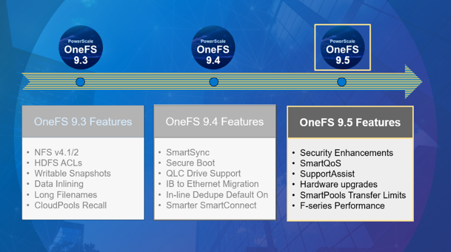
Improving performance for the most demanding workloads
OneFS 9.5 unlocks dramatic performance gains, particularly for the all-flash NVMe platforms, where the PowerScale F900 can now support line-rate streaming reads. SmartCache enhancements allow OneFS 9.5 to deliver streaming read performance gains of up to 55% on the F-series nodes, F600 and F9003, delivering benefit to media and entertainment workloads, plus AI, machine learning, deep learning, and more.
Enhancements to SmartPools in OneFS 9.5 introduce configurable transfer limits. These limits include maximum capacity thresholds, expressed as a percentage, above which SmartPools will not attempt to move files to a particular tier, boosting both reliability and tiering performance.
Granular cluster performance control is enabled with the debut of PowerScale SmartQoS, which allows admins to configure limits on the maximum number of protocol operations that NFS, S3, SMB, or mixed protocol workloads can consume.
Enhancing enterprise-grade supportability and serviceability
OneFS 9.5 enables SupportAssist, Dell’s next generation remote connectivity system for transmitting events, logs, and telemetry from a PowerScale cluster to Dell Support. SupportAssist provides a full replacement for ESRS, as well as enabling Dell Support to perform remote diagnosis and remediation of cluster issues.
Upgrading to OneFS 9.5
The new OneFS 9.5 code is available on the Dell Technologies Support site, as both an upgrade and reimage file, allowing both installation and upgrade of this new release.
Author: Nick Trimbee
[1] Based on Dell analysis, August 2021.
[2] Based on Dell analysis comparing cybersecurity software capabilities offered for Dell PowerScale vs. competitive products, September 2022.
[3] Based on Dell internal testing, January 2023. Actual results will vary.

OneFS Diagnostics
Sun, 18 Dec 2022 19:43:36 -0000
|Read Time: 0 minutes
In addition to the /usr/bin/isi_gather_info tool, OneFS also provides both a GUI and a common ‘isi’ CLI version of the tool – albeit with slightly reduced functionality. This means that a OneFS log gather can be initiated either from the WebUI, or by using the ‘isi diagnostics’ CLI command set with the following syntax:
# isi diagnostics gather start
The diagnostics gather status can also be queried as follows:
# isi diagnostics gather status Gather is running.
When the command has completed, the gather tarfile can be found under /ifs/data/Isilon_Support.
You can also view and modify the ‘isi diagnostics’ configuration as follows:
# isi diagnostics gather settings view Upload: Yes ESRS: Yes Supportassist: Yes Gather Mode: full HTTP Insecure Upload: No HTTP Upload Host: HTTP Upload Path: HTTP Upload Proxy: HTTP Upload Proxy Port: - Ftp Upload: Yes Ftp Upload Host: ftp.isilon.com Ftp Upload Path: /incoming Ftp Upload Proxy: Ftp Upload Proxy Port: - Ftp Upload User: anonymous Ftp Upload Ssl Cert: Ftp Upload Insecure: No
The configuration options for the ‘isi diagnostics gather’ CLI command include:
Option | Description |
–upload <boolean> | Enable gather upload. |
–esrs <boolean> | Use ESRS for gather upload. |
–gather-mode (incremental | full) | Type of gather: incremental, or full. |
–http-insecure-upload <boolean> | Enable insecure HTTP upload on completed gather. |
–http-upload-host <string> | HTTP Host to use for HTTP upload. |
–http-upload-path <string> | Path on HTTP server to use for HTTP upload. |
–http-upload-proxy <string> | Proxy server to use for HTTP upload. |
–http-upload-proxy-port <integer> | Proxy server port to use for HTTP upload. |
–clear-http-upload-proxy-port | Clear proxy server port to use for HTTP upload. |
–ftp-upload <boolean> | Enable FTP upload on completed gather. |
–ftp-upload-host <string> | FTP host to use for FTP upload. |
–ftp-upload-path <string> | Path on FTP server to use for FTP upload. |
–ftp-upload-proxy <string> | Proxy server to use for FTP upload. |
–ftp-upload-proxy-port <integer> | Proxy server port to use for FTP upload. |
–clear-ftp-upload-proxy-port | Clear proxy server port to use for FTP upload. |
–ftp-upload-user <string> | FTP user to use for FTP upload. |
–ftp-upload-ssl-cert <string> | Specifies the SSL certificate to use in FTPS connection. |
–ftp-upload-insecure <boolean> | Whether to attempt a plain text FTP upload. |
–ftp-upload-pass <string> | FTP user to use for FTP upload password. |
–set-ftp-upload-pass | Specify the FTP upload password interactively. |
As mentioned above, ‘isi diagnostics gather’ does not present quite as broad an array of features as the isi_gather_info utility. This is primarily for security purposes, because ‘isi diagnostics’ does not require root privileges to run. Instead, a user account with the ‘ISI_PRIV_SYS_SUPPORT’ RBAC privilege is needed in order to run a gather from either the WebUI or ‘isi diagnostics gather’ CLI interface.
When a gather is running, a second instance cannot be started from any other node until that instance finishes. Typically, a warning similar to the following appears:
"It appears that another instance of gather is running on the cluster somewhere. If you would like to force gather to run anyways, use the --force-multiple-igi flag. If you believe this message is in error, you may delete the lock file here: /ifs/.ifsvar/run/gather.node."
You can remove this lock as follows:
# rm -f /ifs/.ifsvar/run/gather.node
You can also initiate a log gather from the OneFS WebUI by navigating to Cluster management > Diagnostics > Gather:
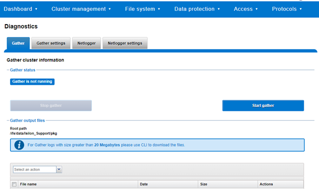
The WebUI also uses the ‘isi diagnostics’ platform API handler and so, like the CLI command, also offers a subset of the full isi_gather_info functionality.
A limited menu of configuration options is also available in the WebUI, under Cluster management > Diagnostics > Gather settings:
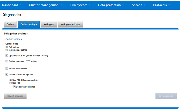
Also contained within the OneFS diagnostics command set is the ‘isi diagnostics netlogger’ utility. Netlogger captures IP traffic over a period of time for network and protocol analysis.
Under the hood, netlogger is a Python wrapper around the ubiquitous tcpdump utility, and can be run either from the OneFS command line or WebUI.
For example, from the WebUI, browse to Cluster management > Diagnostics > Netlogger:
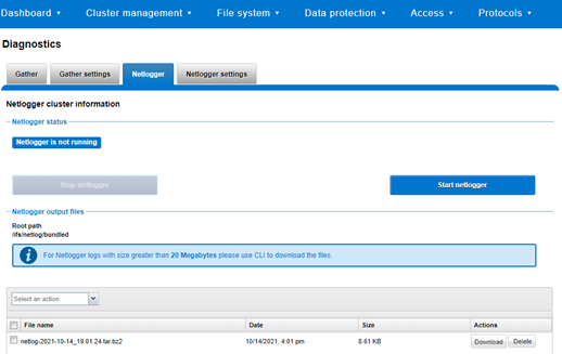
Alternatively, from the OneFS CLI, the isi_netlogger command captures traffic on the interface (‘–interfaces’) over a timeout period of minutes (‘–duration’), and stores a specified number of log files (‘–count’).
Here’s the basic syntax of the CLI utility:
# isi diagnostics netlogger start
[--interfaces <str>]
[--count <integer>]
[--duration <duration>]
[--snaplength <integer>]
[--nodelist <str>]
[--clients <str>]
[--ports <str>]
[--protocols (ip | ip6 | arp | tcp | udp)]
[{--help | -h}]Note that using the ‘-b’ bpf buffer size option will temporarily change the default buffer size while netlogger is running.
To display help text for netlogger command options, specify 'isi diagnostics netlogger start -h'. The command options include:
Netlogger Option | Description |
–interfaces <str> | Limit packet collection to specified network interfaces. |
–count <integer> | The number of packet capture files to keep after they reach the duration limit. Defaults to the latest 3 files. 0 is infinite. |
–duration <duration> | How long to run the capture before rotating the capture file. Default is 10 minutes. |
–snaplength <integer> | The maximum amount of data for each packet that is captured. Default is 320 bytes. Valid range is 64 to 9100 bytes. |
–nodelist <str> | List of nodes specified by LNN on which to run the capture. |
–clients <str> | Limit packet collection to specified Client hostname / IP addresses. |
–ports <str> | Limit packet collection to specified TCP or UDP ports. |
–protocols (ip | ip6 | arp | tcp | udp) | Limit packet collection to specified protocols. |
Netlogger’s log files are stored by default under /ifs/netlog/<node_name>.
You can also use the WebUI to configure the netlogger parameters under Cluster management > Diagnostics > Netlogger settings:
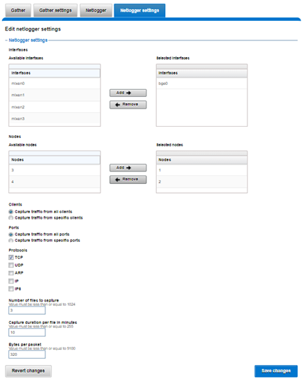
Be aware that specifying ‘isi diagnostics netlogger’ can consume significant cluster resources. When running the tool on a production cluster, be aware of the effect on the system.
When the command has completed, the capture file(s) are stored under:
# /ifs/netlog/[nodename]
You can also use the following command to incorporate netlogger output files into a gather_info bundle:
# isi_gather_info -n [node#] -f /ifs/netlog
To capture on multiple nodes of the cluster, you can prefix the netlogger command by the versatile isi_for_array utility. For example:
# isi_for_array –s ‘isi diagnostics netlogger --nodelist 2,3 --timeout 5 --snaplength 256’
This command syntax creates five minute incremental files on nodes 2 and 3, using a snaplength of 256 bytes, which captures the first 256 bytes of each packet. These five-minute logs are kept for about three days. The naming convention is of the form netlog-<node_name>-<date>-<time>.pcap. For example:
# ls /ifs/netlog/tme_h700-1 netlog-tme_h700-1.2022-09-02_10.31.28.pcap
When using netlogger, set the ‘–snaplength’ option appropriately, depending on the protocol, in order to capture the right amount of detail in the packet headers and/or payload. Or, if you want the entire contents of every packet, use a value of zero (‘–snaplength 0’).
The default snaplength for netlogger is to capture 320 bytes per packet, which is typically sufficient for most protocols.
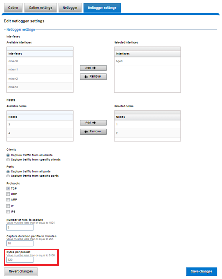
However, for SMB, a snaplength of 512 is sometimes required. Note that depending on a node’s traffic quantity, a snaplength of 0 (that is: capture whole packet) can potentially overwhelm the network interface driver.
All the output gets written to files under /ifs/netlog directory, and the default capture time is ten minutes (‘–duration 10’).
You can apply filters to constrain traffic to/from certain hosts or protocols. For example, to limit output to traffic between client 10.10.10.1 and the cluster node:
# isi diagnostics netlogger --duration 5 --snaplength 256 --clients 10.10.10.1
Or to capture only NFS traffic, filter on port 2049:
# isi diagnostics netlogger --ports 2049
Author: Nick Trimbee

OneFS Logfile Collection with isi-gather-info
Sun, 18 Dec 2022 19:11:11 -0000
|Read Time: 0 minutes
The previous blog outlining the investigation and troubleshooting of OneFS deadlocks and hang-dumps generated several questions about OneFS logfile gathering. So it seemed like a germane topic to explore in an article.
The OneFS ‘isi_gather_info’ utility has long been a cluster staple for collecting and collating context and configuration that primarily aids support in the identification and resolution of bugs and issues. As such, it is arguably OneFS’ primary support tool and, in terms of actual functionality, it performs the following roles:
- Executes many commands, scripts, and utilities on cluster, and saves their results
- Gathers all these files into a single ‘gzipped’ package.
- Transmits the gather package back to Dell, using several optional transport methods.
By default, a log gather tarfile is written to the /ifs/data/Isilon_Support/pkg/ directory. It can also be uploaded to Dell using the following means:
Transport Mechanism | Description | TCP Port |
ESRS | Uses Dell EMC Secure Remote Support (ESRS) for gather upload. | 443/8443 |
FTP | Use FTP to upload completed gather. | 21 |
HTTP | Use HTTP to upload gather. | 80/443 |
More specifically, the ‘isi_gather_info’ CLI command syntax includes the following options:
Option | Description |
–upload <boolean> | Enable gather upload. |
–esrs <boolean> | Use ESRS for gather upload. |
–gather-mode (incremental | full) | Type of gather: incremental, or full. |
–http-insecure-upload <boolean> | Enable insecure HTTP upload on completed gather. |
–http-upload-host <string> | HTTP Host to use for HTTP upload. |
–http-upload-path <string> | Path on HTTP server to use for HTTP upload. |
–http-upload-proxy <string> | Proxy server to use for HTTP upload. |
–http-upload-proxy-port <integer> | Proxy server port to use for HTTP upload. |
–clear-http-upload-proxy-port | Clear proxy server port to use for HTTP upload. |
–ftp-upload <boolean> | Enable FTP upload on completed gather. |
–ftp-upload-host <string> | FTP host to use for FTP upload. |
–ftp-upload-path <string> | Path on FTP server to use for FTP upload. |
–ftp-upload-proxy <string> | Proxy server to use for FTP upload. |
–ftp-upload-proxy-port <integer> | Proxy server port to use for FTP upload. |
–clear-ftp-upload-proxy-port | Clear proxy server port to use for FTP upload. |
–ftp-upload-user <string> | FTP user to use for FTP upload. |
–ftp-upload-ssl-cert <string> | Specifies the SSL certificate to use in FTPS connection. |
–ftp-upload-insecure <boolean> | Whether to attempt a plain text FTP upload. |
–ftp-upload-pass <string> | FTP user to use for FTP upload password. |
–set-ftp-upload-pass | Specify the FTP upload password interactively. |
When the gather arrives at Dell, it is automatically unpacked by a support process and analyzed using the ‘logviewer’ tool.
Under the hood, there are two principal components responsible for running a gather. These are:
Component | Description |
Overlord | The manager process, triggered by the user, which oversees all the isi_gather_info tasks that are executed on a single node. |
Minion | The worker process, which runs a series of commands (specified by the overlord) on a specific node. |
The ‘isi_gather_info’ utility is primarily written in Python, with its configuration under the purview of MCP, and RPC services provided by the isi_rpc_d daemon.
For example:
# isi_gather_info& # ps -auxw | grep -i gather root 91620 4.4 0.1 125024 79028 1 I+ 16:23 0:02.12 python /usr/bin/isi_gather_info (python3.8) root 91629 3.2 0.0 91020 39728 - S 16:23 0:01.89 isi_rpc_d: isi.gather.minion.minion.GatherManager (isi_rpc_d) root 93231 0.0 0.0 11148 2692 0 D+ 16:23 0:00.01 grep -i gather
The overlord uses isi_rdo (the OneFS remote command execution daemon) to start up the minion processes and informs them of the commands to be executed by an ephemeral XML file, typically stored at /ifs/.ifsvar/run/<uuid>-gather_commands.xml. The minion then spins up an executor and a command for each entry in the XML file.
The parallel process executor (the default one to use) acts as a pool, triggering commands to run in parallel until a specified number are running in parallel. The commands themselves take care of the running and processing of results, checking frequently to ensure that the timeout threshold has not been passed.
The executor also keeps track of which commands are currently running, and how many are complete, and writes them to a file so that the overlord process can display useful information. When this is complete, the executor returns the runtime information to the minion, which records the benchmark file. The executor will also safely shut itself down if the isi_gather_info lock file disappears, such as if the isi_gather_info process is killed.
During a gather, the minion returns nothing to the overlord process, because the output of its work is written to disk.
Architecturally, the ‘gather’ process comprises an eight phase workflow:
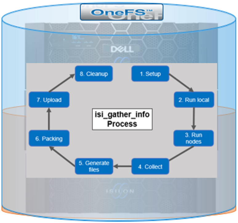
The details of each phase are as follows:
Phase | Description |
1. Setup | Reads from the arguments passed in, and from any config files on disk, and sets up the config dictionary, which will be used throughout the rest of the codebase. Most of the code for this step is contained in isilon/lib/python/gather/igi_config/configuration.py. This is also the step where the program is most likely to exit, if some config arguments end up being invalid. |
2. Run local | Executes all the cluster commands, which are run on the same node that is starting the gather. All these commands run in parallel (up to the current parallelism value). This is typically the second longest running phase. |
3. Run nodes | Executes the node commands across all of the cluster’s nodes. This runs on each node, and while these commands run in parallel (up to the current parallelism value), they do not run in parallel with the local step. |
4. Collect | Ensures that all results end up on the overlord node (the node that started gather). If gather is using /ifs, it is very fast, but if it’s not, it needs to SCP all the node results to a single node. |
5. Generate Extra Files | Generates nodes_info and package_info.xml. These two files are present in every single gather, and tell us some important metadata about the cluster. |
6. Packing | Packs (tars and gzips) all the results. This is typically the longest running phase, often by an order of magnitude. |
7. Upload | Transports the tarfile package to its specified destination. Depending on the geographic location, this phase might also be lengthy. |
8. Cleanup | Cleans up any intermediary files that were created on cluster. This phase will run even if gather fails or is interrupted. |
Because the isi_gather_info tool is primarily intended for troubleshooting clusters with issues, it runs as root (or compadmin in compliance mode), because it needs to be able to execute under degraded conditions (that is, without GMP, during upgrade, and under cluster splits, and so on). Given these atypical requirements, isi_gather_info is built as a stand-alone utility, rather than using the platform API for data collection.
The time it takes to complete a gather is typically determined by cluster configuration, rather than size. For example, a gather on a small cluster with a large number of NFS shares will take significantly longer than on large cluster with a similar NFS configuration. Incremental gathers are not recommended, because the base that’s required to check against in the log store may be deleted. By default, gathers only persist for two weeks in the log processor.
On completion of a gather, a tar’d and zipped logset is generated and placed under the cluster’s /ifs/data/IsilonSupport/pkg directory by default. A standard gather tarfile unpacks to the following top-level structure:
# du -sh * 536M IsilonLogs-powerscale-f900-cl1-20220816-172533-3983fba9-3fdc-446c-8d4b-21392d2c425d.tgz 320K benchmark 24K celog_events.xml 24K command_line 128K complete 449M local 24K local.log 24K nodes_info 24K overlord.log 83M powerscale-f900-cl1-1 24K powerscale-f900-cl1-1.log 119M powerscale-f900-cl1-2 24K powerscale-f900-cl1-2.log 134M powerscale-f900-cl1-3 24K powerscale-f900-cl1-3.log
In this case, for a three node F900 cluster, the compressed tarfile is 536 MB in size. The bulk of the data, which is primarily CLI command output, logs, and sysctl output, is contained in the ‘local’ and individual node directories (powerscale-f900-cl1-*). Each node directory contains a tarfile, varlog.tar, containing all the pertinent logfiles for that node.
The root directory of the tarfile file includes the following:
Item | Description |
benchmark | § Runtimes for all commands executed by the gather. |
celog_events.xml |
§ Cluster/Node names § Node Serial numbers § Configuration ID § OneFS version info § Events |
complete | § Lists of complete commands run across the cluster and on individual nodes |
local |
|
nodes_info |
|
overlord.log | § Gather execution and issue log. |
package_info.xml | § Cluster version details, GUID, S/N, and customer info (name, phone, email, and so on). |
command_line |
|
Notable contents of the ‘local’ directory (all the cluster-wide commands that are executed on the node running the gather) include:
Local Contents Item | Description |
isi_alerts_history
|
|
isi_job_list |
|
isi_job_schedule |
|
isi_license |
|
isi_network_interfaces | § State and configuration of all the cluster’s network interfaces. |
isi_nfs_exports | § Configuration detail for all the cluster’s NFS exports. |
isi_services | § Listing of all the OneFS services and whether they are enabled or disabled. More detailed configuration for each service is contained in separate files. For example, for SnapshotIQ:
|
isi_smb | § Detailed configuration info for all the cluster’s NFS exports. |
isi_stat | § Overall status of the cluster, including networks, drives, and so on. |
isi_statistics | § CPU, protocol, and disk IO stats. |
Contents of the directory for the ‘node’ directory include:
Node Contents Item | Description |
df | Output of the df command |
du |
|
isi_alerts | Contains a list of outstanding alerts on the node |
ps and ps_full | Lists of all running process at the time that isi_gather_info was executed. |
As the isi_gather_info command runs, status is provided in the interactive CLI session:
# isi_gather_info Configuring COMPLETE running local commands IN PROGRESS \ Progress of local [######################################################## ] 147/152 files written \ Some active commands are: ifsvar_modules_jobengine_cp, isi_statistics_heat, ifsv ar_modules
When the gather has completed, the location of the tarfile on the cluster itself is reported as follows:
# isi_gather_info Configuring COMPLETE running local commands COMPLETE running node commands COMPLETE collecting files COMPLETE generating package_info.xml COMPLETE tarring gather COMPLETE uploading gather COMPLETE
The path to the tar-ed gather is:
/ifs/data/Isilon_Support/pkg/IsilonLogs-h5001-20220830-122839-23af1154-779c-41e9-b0bd-d10a026c9214.tgz
If the gather upload services are unavailable, errors are displayed on the console, as shown here:
… uploading gather FAILED ESRS failed - ESRS has not been provisioned FTP failed - pycurl error: (28, 'Failed to connect to ftp.isilon.com port 21 after 81630 ms: Operation timed out')
Author: Nick Trimbee

OneFS Hardware Network Considerations
Wed, 07 Dec 2022 20:54:43 -0000
|Read Time: 0 minutes
As we’ve seen in prior articles in this series, OneFS and the PowerScale platforms support a variety of Ethernet speeds, cable and connector styles, and network interface counts, depending on the node type selected. However, unlike the back-end network, Dell Technologies does not specify particular front-end switch models, allowing PowerScale clusters to seamlessly integrate into the data link layer (layer 2) of an organization’s existing Ethernet IP network infrastructure. For example:
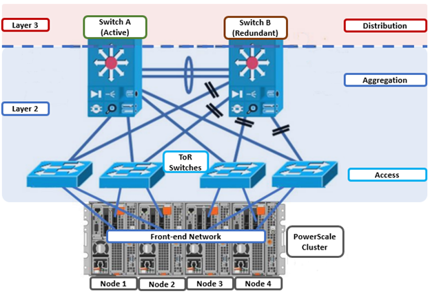
A layer 2 looped topology, as shown here, extends VLANs between the distribution/aggregation switches, with spanning tree protocol (STP) preventing network loops by shutting down redundant paths. The access layer uplinks can be used to load balance VLANs. This distributed architecture allows the cluster’s external network to connect to multiple access switches, affording each node similar levels of availability, performance, and management properties.
Link aggregation can be used to combine multiple Ethernet interfaces into a single link-layer interface, and is implemented between a single switch and a PowerScale node, where transparent failover or switch port redundancy is required. Link aggregation assumes that all links are full duplex, point to point, and at the same data rate, providing graceful recovery from link failures. If a link fails, traffic is automatically sent to the next available link without disruption.
Quality of service (QoS) can be implemented through differentiated services code point (DSCP), by specifying a value in the packet header that maps to an ‘effort level’ for traffic. Because OneFS does not provide an option for tagging packets with a specified DSCP marking, the recommended practice is to configure the first hop ports to insert DSCP values on the access switches connected to the PowerScale nodes. OneFS does however retain headers for packets that already have a specified DSCP value.
When designing a cluster, the recommendation is that each node have at least one front-end interface configured, preferably in at least one static SmartConnect zone. Although a cluster can be run in a ‘not all nodes on the network’ (NANON) configuration, where feasible, the recommendation is to connect all nodes to the front-end network(s). Additionally, cluster services such as SNMP, ESRS, ICAP, and auth providers (AD, LDAP, NIS, and so on) prefer that each node have an address that can reach the external servers.
In contrast with scale-up NAS platforms that use separate network interfaces for out-of-band management and configuration, OneFS traditionally performs all cluster network management in-band. However, PowerScale nodes typically contain a dedicated 1Gb Ethernet port that can be configured for use as a management network by ICMP or iDRAC, simplifying administration of a large cluster. OneFS also supports using a node’s serial port as an RS-232 out-of-band management interface. This practice is highly recommended for large clusters. Serial connectivity can provide reliable BIOS-level command line access for on-site or remote service staff to perform maintenance, troubleshooting, and installation operations.
SmartConnect provides a configurable allocation method for each IP address pool:
Allocation Method | Attributes |
Static | • One IP per interface is assigned, will likely require fewer IPs to meet minimum requirements • No Failover of IPs to other interfaces |
Dynamic | • Multiple IPs per interface is assigned, will require more IPs to meet minimum requirements • Failover of IPs to other interfaces, failback policies are needed |
The default ‘static’ allocation assigns a single persistent IP address to each interface selected in the pool, leaving additional pool IP addresses unassigned if the number of addresses exceeds the total interfaces.
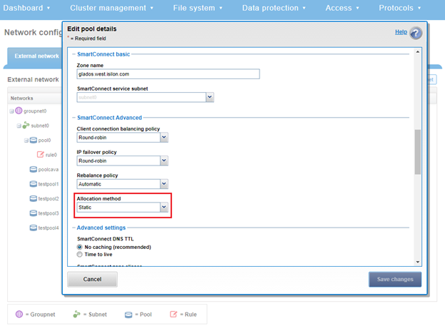
The lowest IP address of the pool is assigned to the lowest Logical Node Number (LNN) from the selected interfaces. The same is true for the second-lowest IP address and LNN, and so on. If a node or interface becomes unavailable, this IP address does not move to another node or interface. Also, when the node or interface becomes unavailable, it is removed from the SmartConnect zone, and new connections will not be assigned to the node. When the node is available again, SmartConnect automatically adds it back into the zone and assigns new connections.
By contrast, ‘dynamic’ allocation divides all available IP addresses in the pool across all selected interfaces. OneFS attempts to assign the IP addresses as evenly as possible. However, if the interface-to-IP address ratio is not an integer value, a single interface might have more IP addresses than another. As such, wherever possible, ensure that all the interfaces have the same number of IP addresses.
In concert with dynamic allocation, dynamic failover provides high availability by transparently migrating IP addresses to another node when an interface is not available. If a node becomes unavailable, all the IP addresses it was hosting are reallocated across the new set of available nodes in accordance with the configured failover load-balancing policy. The default IP address failover policy is round robin, which evenly distributes IP addresses from the unavailable node across available nodes. Because the IP address remains consistent, irrespective of the node on which it resides, failover to the client is transparent, so high availability is seamless.
The other available IP address failover policies are the same as the initial client connection balancing policies, that is, connection count, throughput, or CPU usage. In most scenarios, round robin is not only the best option but also the most common. However, the other failover policies are available for specific workflows.
The decision on whether to implement dynamic failover depends on the protocol(s) being used, general workflow attributes, and any high-availability design requirements:
Protocol | State | Suggested Allocation Strategy |
NFSv3 | Stateless | Dynamic |
NFSv4 | Stateful | Dynamic or Static, depending on mount daemon, OneFS version, and Kerberos. |
SMB | Stateful | Dynamic or Static |
SMB Multi-channel | Stateful | Dynamic or Static |
S3 | Stateless | Dynamic or Static |
HDFS | Stateful | Dynamic or Static. HDFS uses separate name-node and data-node connections. Allocation strategy depends on the need for data locality and/or multi-protocol, that is:
HDFS + NFSv3 : Dynamic Pool
HDFS + SMB : Static Pool |
HTTP | Stateless | Static |
FTP | Stateful | Static |
SyncIQ | Stateful | Static required |
Assigning each workload or data store to a unique IP address enables OneFS SmartConnect to move each workload to one of the other interfaces. This minimizes the additional work that a remaining node in the SmartConnect pool must absorb and ensures that the workload is evenly distributed across all the other nodes in the pool.
Static IP pools require one IP address for each logical interface within the pool. Because each node provides two interfaces for external networking, if link aggregation is not configured, this would require 2*N IP addresses for a static pool.
Determining the number of IP addresses within a dynamic allocation pool varies depending on the workflow, node count, and the estimated number of clients that would be in a failover event. While dynamic pools need, at a minimum, the number of IP addresses to match a pool’s node count, the ‘N * (N – 1)’ formula can often prove useful for calculating the required number of IP addresses for smaller pools. In this equation, N is the number of nodes that will participate in the pool.
For example, a SmartConnect pool with four-node interfaces, using the ‘N * (N – 1)’ model will result in three unique IP addresses being allocated to each node. A failure on one node interface will cause each of that interface’s three IP addresses to fail over to a different node in the pool. This ensures that each of the three active interfaces remaining in the pool receives one IP address from the failed node interface. If client connections to that node are evenly balanced across its three IP addresses, SmartConnect will evenly distribute the workloads to the remaining pool members. For larger clusters, this formula may not be feasible due to the sheer number of IP addresses required.
Enabling jumbo frames (Maximum Transmission Unit set to 9000 bytes) typically yields improved throughput performance with slightly reduced CPU usage than when using standard frames, where the MTU is set to 1500 bytes. For example, with 40 Gb Ethernet connections, jumbo frames provide about five percent better throughput and about one percent less CPU usage.
OneFS provides the ability to optimize storage performance by designating zones to support specific workloads or subsets of clients. Different network traffic types can be segregated on separate subnets using SmartConnect pools.
For large clusters, partitioning the cluster’s networking resources and allocating bandwidth to each workload can help minimize the likelihood that heavy traffic from one workload will affect network throughput for another. This is particularly true for SyncIQ replication and NDMP backup traffic, which can frequently benefit from its own set of interfaces, separate from user and client IO load.
The ‘groupnet’ networking object is part of OneFS’ support for multi-tenancy. Groupnets sit above subnets and pools and allow separate Access Zones to contain distinct DNS settings.
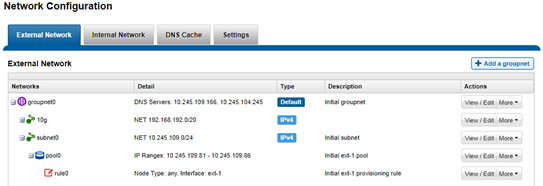
The management and data network(s) can then be incorporated into different Access Zones, each with their own DNS, directory access services, and routing, as appropriate.
Author: Nick Trimbee

OneFS Hardware Platform Considerations
Wed, 07 Dec 2022 20:42:17 -0000
|Read Time: 0 minutes
A key decision for performance, particularly in a large cluster environment, is the type and quantity of nodes deployed. Heterogeneous clusters can be architected with a wide variety of node styles and capacities, to meet the needs of a varied data set and a wide spectrum of workloads. These node styles encompass several hardware generations, and fall loosely into three main categories or tiers. While heterogeneous clusters can easily include many hardware classes and configurations, the best practice of simplicity for building clusters holds true here too.
Consider the physical cluster layout and environmental factors, particularly when designing and planning a large cluster installation. These factors include:
- Redundant power supply
- Airflow and cooling
- Rackspace requirements
- Floor tile weight constraints
- Networking requirements
- Cabling distance limitations
The following table details the physical dimensions, weight, power draw, and thermal properties for the range of PowerScale F-series all-flash nodes:
Model | Tier | Height | Width | Depth | RU | Weight | Max Watts | Watts | Max BTU | Normal BTU |
F900 | All-flash NVMe performance | 2U | 17.8 IN / | 31.8 IN / 85.9 cm | 2RU | 73 lbs | 1297 | 859 | 4425 | 2931 |
F600 | All-flash NVMe Performance | 1U (1.75IN) | 17.8 IN / | 31.8 IN / 85.9 cm | 1RU | 43 lbs | 467 | 718 | 2450 | 1594 |
F200 | All-flash | 1U (1.75IN) | 17.8 IN / | 31.8 IN / 85.9 cm | 1RU | 47 lbs | 395 | 239 | 1346 | 816 |
Note that the table above represents individual nodes. A minimum of three similar nodes are required for a node pool.
Similarly, the following table details the physical dimensions, weight, power draw, and thermal properties for the range of PowerScale chassis-based platforms:
Model | Tier | Height | Width | Depth | RU | Weight | Max Watts | Watts | Max BTU | Normal BTU |
F800/ | All-flash performance | 4U (4×1.75IN) | 17.6 IN / 45 cm | 35 IN / | 4RU | 169 lbs (77 kg) | 1764 | 1300 | 6019 | 4436 |
H700 |
Hybrid/Utility | 4U (4×1.75IN) | 17.6 IN / 45 cm | 35 IN / | 4RU | 261lbs (100 kg) | 1920 | 1528 | 6551 | 5214 |
H7000 |
Hybrid/Utility | 4U (4×1.75IN) | 17.6 IN / 45 cm | 39 IN / | 4RU | 312 lbs (129 kg) | 2080 | 1688 | 7087 | 5760 |
H600 |
Hybrid/Utility | 4U (4×1.75IN) | 17.6 IN / 45 cm | 35 IN / | 4RU | 213 lbs (97 kg) | 1990 | 1704 | 6790 | 5816 |
H5600 |
Hybrid/Utility | 4U (4×1.75IN) | 17.6 IN / 45 cm | 39 IN / | 4RU | 285 lbs (129 kg) | 1906 | 1312 | 6504 | 4476 |
H500 |
Hybrid/Utility | 4U (4×1.75IN) | 17.6 IN / 45 cm | 35 IN / | 4RU | 248 lbs (112 kg) | 1906 | 1312 | 6504 | 4476 |
H400 |
Hybrid/Utility | 4U (4×1.75IN) | 17.6 IN / 45 cm | 35 IN / | 4RU | 242 lbs (110 kg) | 1558 | 1112 | 5316 | 3788 |
A300 |
Archive | 4U (4×1.75IN) | 17.6 IN / 45 cm | 35 IN / | 4RU | 252 lbs (100 kg) | 1460 | 1070 | 4982 | 3651 |
A3000 |
Archive | 4U (4×1.75IN) | 17.6 IN / 45 cm | 39 IN / | 4RU | 303 lbs (129 kg) | 1620 | 1230 | 5528 | 4197 |
A200 |
Archive | 4U (4×1.75IN) | 17.6 IN / 45 cm | 35 IN / | 4RU | 219 lbs (100 kg) | 1460 | 1052 | 4982 | 3584 |
A2000 |
Archive | 4U (4×1.75IN) | 17.6 IN / 45 cm | 39 IN / | 4RU | 285 lbs (129 kg) | 1520 | 1110 | 5186 | 3788 |
Note that this table represents 4RU chassis, each of which contains four PowerScale platform nodes (the minimum node pool size).
The following figure shows the locations of both the front-end (ext-1 & ext-2) and back-end (int-1 & int-2) network interfaces on the PowerScale stand-alone F-series and chassis-based nodes:
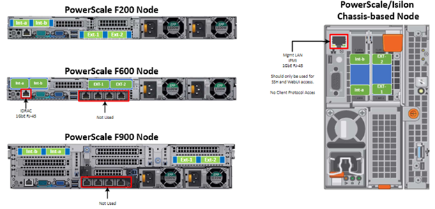
A PowerScale cluster’s back-end network is analogous to a distributed systems bus. Each node has two back-end interfaces for redundancy that run in an active/passive configuration (int-1 and int-2 above). The primary interface is connected to the primary switch; the secondary interface is connected to a separate switch.
For nodes using 40/100 Gb or 25/10 Gb Ethernet or InfiniBand connected with multimode fiber, the maximum cable length is 150 meters. This allows a cluster to span multiple rack rows, floors, and even buildings, if necessary. While this can solve floor space challenges, in order to perform any physical administration activity on nodes, you must know where the equipment is located.
The following table shows the various PowerScale node types and their respective back-end network support. While Ethernet is the preferred medium – particularly for large PowerScale clusters – InfiniBand is also supported for compatibility with legacy Isilon clusters.
Node Models | Details |
F200, F600, F900 | F200: nodes support a 10 GbE or 25 GbE connection to the access switch using the same NIC. A breakout cable can connect up to four nodes to a single switch port.
F600: nodes support a 40 GbE or 100 GbE connection to the access switch using the same NIC.
F900: nodes support a 40 GbE or 100 GbE connection to the access switch using the same NIC. |
H700, H7000, A300, A3000 | Supports 40 GbE or 100 GbE connection to the access switch using the same NIC.
OR
Supports 25 GbE or 10 GbE connection to the leaf using the same NIC. A breakout cable can connect a 40 GbE switch port to four 10 GbE nodes or a 100 GbE switch port to four 25 GbE nodes. |
F810, F800, H600, H500, H5600 | Performance nodes support a 40 GbE connection to the access switch. |
A200, A2000, H400 | Archive nodes support a 10GbE connection to the access switch using a breakout cable. A breakout cable can connect a 40 GbE switch port to four 10 GbE nodes or a 100 GbE switch port to four 10 GbE nodes. |
Currently only Dell Technologies approved switches are supported for back-end Ethernet and IB cluster interconnection. These include:
Switch | Port | Port | Height | Role | Notes |
Dell S4112 | 24 | 10GbE | ½ | ToR | 10 GbE only. |
Dell 4148 | 48 | 10GbE | 1 | ToR | 10 GbE only. |
Dell S5232 | 32 | 100GbE | 1 | Leaf or Spine | Supports 4x10GbE or 4x25GbE breakout cables.
Total of 124 10GbE or 25GbE nodes as top-of-rack back-end switch.
Port 32 does not support breakout. |
Dell Z9100 | 32 | 100GbE | 1 | Leaf or Spine | Supports 4x10GbE or 4x25GbE breakout cables.
Total of 128 10GbE or 25GbE nodes as top-of-rack back-end switch. |
Dell Z9264 | 64 | 100GbE | 2 | Leaf or Spine | Supports 4x10GbE or 4x25GbE breakout cables.
Total of 128 10GbE or 25GbE nodes as top-of-rack back-end switch. |
Arista 7304 | 128 | 40GbE | 8 | Enterprise core | 40GbE or 10GbE line cards. |
Arista 7308 | 256 | 40GbE | 13 | Enterprise/ large cluster | 40GbE or 10GbE line cards. |
Mellanox Neptune MSX6790 | 36 | QDR | 1 | IB fabric | 32Gb/s quad data rate InfiniBand. |
Be aware that the use of patch panels is not supported for PowerScale cluster back-end connections, regardless of overall cable lengths. All connections must be a single link, single cable directly between the node and back-end switch. Also, Ethernet and InfiniBand switches must not be reconfigured or used for any traffic beyond a single cluster.
Support for leaf spine back-end Ethernet network topologies was first introduced in OneFS 8.2. In a leaf-spine network switch architecture, the PowerScale nodes connect to leaf switches at the access, or leaf, layer of the network. At the next level, the aggregation and core network layers are condensed into a single spine layer. Each leaf switch connects to each spine switch to ensure that all leaf switches are no more than one hop away from one another. For example:
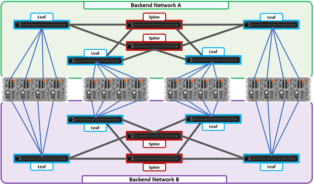
Leaf-to-spine switch connections require even distribution, to ensure the same number of spine connections from each leaf switch. This helps minimize latency and reduces the likelihood of bottlenecks in the back-end network. By design, a leaf spine network architecture is both highly scalable and redundant.
Leaf spine network deployments can have a minimum of two leaf switches and one spine switch. For small to medium clusters in a single rack, the back-end network typically uses two redundant top-of-rack (ToR) switches, rather than implementing a more complex leaf-spine topology.
Author: Nick Trimbee

OneFS Hardware Installation Considerations
Wed, 07 Dec 2022 20:29:30 -0000
|Read Time: 0 minutes
When it comes to physically installing PowerScale nodes, most use a 35 inch depth chassis and will fit in a standard depth data center cabinet. Nodes can be secured to standard storage racks with their sliding rail kits, included in all node packaging and compatible with racks using either 3/8 inch square holes, 9/32 inch round holes, or 10-32 / 12-24 / M5X.8 / M6X1 pre-threaded holes. These supplied rail kit mounting brackets are adjustable in length, from 24 inches to 36 inches, to accommodate different rack depths. When selecting an enclosure for PowerScale nodes, ensure that the rack supports the minimum and maximum rail kit sizes.
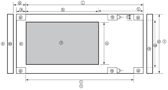
Rack Component | Description |
a | Distance between front surface of the rack and the front NEMA rail |
b | Distance between NEMA rails, minimum=24in (609.6mm), max=34in (863.6mm) |
c | Distance between the rear of the chassis to the rear of the rack, min=2.3in (58.42mm) |
d | Distance between inner front of the front door and the NEMA rail, min=2.5in (63.5mm) |
e | Distance between the inside of the rear post and the rear vertical edge of the chassis and rails, min=2.5in (63.5mm) |
f | Width of the rear rack post |
g | 19in (486.2mm)+(2e), min=24in (609.6mm) |
h | 19in (486.2mm) NEMA+(2e)+(2f) Note: Width of the PDU+0.5in (13mm) <=e +f
If j=i+c+PDU depth+3in (76.2mm), then h=min 23.6in (600mm)
Assuming the PDU is mounted beyond i+c. |
i | Chassis depth: Normal chassis=35.80in (909mm) : Deep chassis=40.40in (1026mm) Switch depth (measured from the front NEMA rail): Note: The inner rail is fixed at 36.25in (921mm)
Allow up to 6in (155mm) for cable bend radius when routing up to 32 cables to one side of the rack. Select the greater of the installed equipment. |
j | Minimum rack depth=i+c |
k | Front |
l | Rear |
m | Front door |
n | Rear door |
p | Rack post |
q | PDU |
r | NEMA |
s | NEMA 19 inch |
t | Rack top view |
u | Distance from front NEMA to chassis face: Dell PowerScale deep and normal chassis = 0in |
However, the high-capacity models, such as the F800/810, H7000, H5600, A3000 and A2000, have 40 inch depth chassis and require extended depth cabinets, such as the APC 3350 or Dell Titan-HD rack.
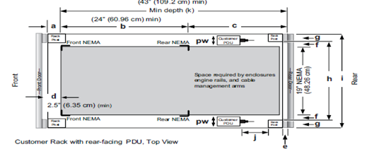
Additional room must be provided for opening the FRU service trays at the rear of the nodes and, in the chassis-based 4RU platforms, the disk sleds at the front of the chassis. Except for the 2RU F900, the stand-alone PowerScale all-flash nodes are 1RU in height (including the 1RU diskless P100 accelerator and B100 backup accelerator nodes).
Power-wise, each cabinet typically requires between two and six independent single or three-phase power sources. To determine the specific requirements, use the published technical specifications and device rating labels for the devices to calculate the total current draw for each rack.
Specification | North American 3 wire connection (2 L and 1 G) | International 3 wire connection (1 L, 1 N, and 1 G) |
Input nominal voltage | 200–240 V ac +/- 10% L – L nom | 220–240 V ac +/- 10% L – L nom |
Frequency | 50–60 Hz | 50–60 Hz |
Circuit breakers | 30 A | 32 A |
Power zones | Two | Two |
Power requirements at site (minimum to maximum) | Single-phase: six 30A drops, two per zone
Three-phase Delta: two 50A drops, one per zone
Three-phase Wye: two 32A drops, one per zone | Single-phase: six 30A drops, two per zone
Three-phase Delta: two 50A drops, one per zone
Three-phase Wye: two 32A drops, one per zone |
Additionally, the recommended environmental conditions to support optimal PowerScale cluster operation are as follows:
Attribute | Details |
Temperature | Operate at >=90 percent of the time between 10 degrees Celsius to 35 degrees Celsius, and <=10 percent of the time between 5 degrees Celsius to 40 degrees Celsius. |
Humidity | 40 to 55 percent relative humidity |
Weight | A fully configured cabinet must sit on at least two floor tiles, and can weigh approximately 1588 kilograms (3500 pounds). |
Altitude | 0 meters to 2439 meters (0 to 8,000 ft) above sea level operating altitude. |
Weight is a critical factor to keep in mind, particularly with the chassis-based nodes. Individual 4RU chassis can weigh up to around 300 lbs each, and the maximum floor tile capacity for each individual cabinet or rack must be kept in mind. For the deep node styles (H7000, H5600, A3000 and A2000), the considerable node weight may prevent racks from being fully populated with PowerScale equipment. If the cluster uses a variety of node types, installing the larger, heavier nodes at the bottom of each rack and the lighter chassis at the top can help distribute weight evenly across the cluster racks’ floor tiles.
Note that there are no lift handles on the PowerScale 4RU chassis. However, the drive sleds can be removed to provide handling points if no lift is available. With all the drive sleds removed, but leaving the rear compute modules inserted, the chassis weight drops to a more manageable 115 lbs or so. It is strongly recommended to use a lift for installation of 4RU chassis.
Cluster back-end switches ship with the appropriate rails (or tray) for proper installation of the switch in the rack. These rail kits are adjustable to fit NEMA front rail to rear rail spacing ranging from 22 in to 34 in.
Note that some manufacturers’ Ethernet switch rails are designed to overhang the rear NEMA rails, helping to align the switch with the PowerScale chassis at the rear of the rack. These require a minimum clearance of 36 in from the front NEMA rail to the rear of the rack, in order to ensure that the rack door can be closed.
Consider the following large cluster topology, for example:
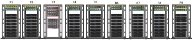
This contiguous rack architecture is designed to scale up to the current maximum PowerScale cluster size of 252 nodes, in 63 4RU chassis, across nine racks as the environment grows – while still keeping cable management relatively simple. Note that this configuration assumes 1RU per node. If you are using F900 nodes, which are 2RU in size, be sure to budget for additional rack capacity.
Successful large cluster infrastructures depend on the proficiency of the installer and their optimizations for maintenance and future expansion. Some good data center design practices include:
- Pre-allocating and reserving adjacent racks in the same isle to accommodate the anticipated future cluster expansion
- Reserving an empty ‘mailbox’ slot in the top half of each rack for any pass-through cable management needs
- Dedicating one of the racks in the group for the back-end and front-end distribution/spine switches – in this case rack R3
For Hadoop workloads, PowerScale clusters are compatible with the rack awareness feature of HDFS to provide balancing in the placement of data. Rack locality keeps the data flow internal to the rack.
Excess cabling can be neatly stored in 12” service coils on a cable tray above the rack, if available, or at the side of the rack as illustrated below.
The use of intelligent power distribution units (PDUs) within each rack can facilitate the remote power cycling of nodes, if desired.
For deep nodes such as the H7000 and A3000 hardware, where chassis depth can be a limiting factor, horizontally mounted PDUs within the rack can be used in place of vertical PDUs, if necessary. If front-mounted, partial depth Ethernet switches are deployed, you can install horizontal PDUs in the rear of the rack directly behind the switches to maximize available rack capacity.
With copper cables (such as SFP+, QSFP, CX4), the maximum cable length is typically limited to 10 meters or less. After factoring in for dressing the cables to maintain some level of organization and proximity within the racks and cable trays, all the racks with PowerScale nodes need to be near each other – either in the same rack row or close by in an adjacent row – or adopt a leaf-spine topology, with leaf switches in each rack.
If greater physical distance between nodes is required, support for multimode fiber (QSFP+, MPO, LC, etc) extends the cable length limitation to 150 meters. This allows nodes to be housed on separate floors or on the far side of a floor in a datacenter if necessary. While solving the floor space problem, this does have the potential to introduce new administrative and management challenges.
The following table lists the various cable types, form factors, and supported lengths available for PowerScale nodes:
Cable Form Factor | Medium | Speed (Gb/s) | Max Length |
QSFP28 | Optical | 100Gb | 30M |
MPO | Optical | 100/40Gb | 150M |
QSFP28 | Copper | 100Gb | 5M |
QSFP+ | Optical | 40Gb | 10M |
LC | Optical | 25/10Gb | 150M |
QSFP+ | Copper | 40Gb | 5M |
SFP28 | Copper | 25Gb | 5M |
SFP+ | Copper | 10Gb | 7M |
CX4 | Copper | IB QDR/DDR | 10M |
The connector types for the cables above can be identified as follows:
As for the nodes themselves, the following rear views indicate the locations of the various network interfaces:
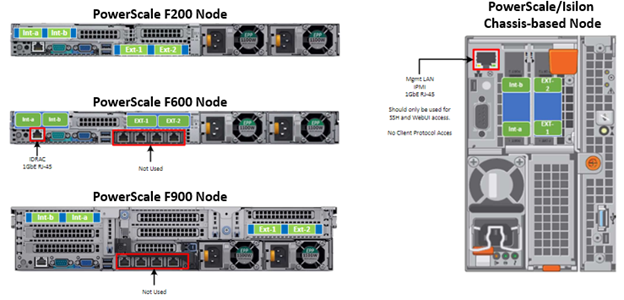
Note that Int-a and int-b indicate the primary and secondary back-end networks, whereas Ext-1 and Ext-2 are the front-end client networks interfaces.
Be aware that damage to the InfiniBand or Ethernet cables (copper or optical fiber) can negatively affect cluster performance. Never bend cables beyond the recommended bend radius, which is typically 10–12 times the diameter of the cable. For example, if a cable is 1.6 inches, round up to 2 inches and multiply by 10 for an acceptable bend radius.
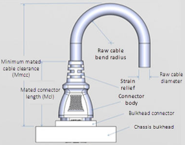
Cables differ, so follow the explicit recommendations of the cable manufacturer.
The most important design attribute for bend radius consideration is the minimum mated cable clearance (Mmcc). Mmcc is the distance from the bulkhead of the chassis through the mated connectors/strain relief including the depth of the associated 90 degree bend. Multimode fiber has many modes of light (fiber optic) traveling through the core. As each of these modes moves closer to the edge of the core, light and the signal are more likely to be reduced, especially if the cable is bent. In a traditional multimode cable, as the bend radius is decreased, the amount of light that leaks out of the core increases, and the signal decreases. Best practices for data cabling include:
- Keep cables away from sharp edges or metal corners.
- Avoid bundling network cables with power cables. If network and power cables are not bundled separately, electromagnetic interference (EMI) can affect the data stream.
- When bundling cables, do not pinch or constrict the cables.
- Avoid using zip ties to bundle cables. Instead use Velcro hook-and-loop ties that do not have hard edges, and can be removed without cutting. Fastening cables with Velcro ties also reduces the impact of gravity on the bend radius.
Note that the effects of gravity can also decrease the bend radius and result in degradation of signal power and quality.
Cables, particularly when bundled, can also obstruct the movement of conditioned air around the cluster, and cables should be secured away from fans. Flooring seals and grommets can be useful to keep conditioned air from escaping through cable holes. Also ensure that smaller Ethernet switches are drawing cool air from the front of the rack, not from inside the cabinet. This can be achieved either with switch placement or by using rack shelving.
Author: Nick Trimbee

OneFS Hardware Environmental and Logistical Considerations
Wed, 07 Dec 2022 17:28:21 -0000
|Read Time: 0 minutes
In this article, we turn our attention to some of the environmental and logistical aspects of cluster design, installation, and management.
In addition to available rack space and physical proximity of nodes, provision needs to be made for adequate power and cooling as the cluster expands. New generations of drives and nodes typically deliver increased storage density, which often magnifies the power draw and cooling requirements per rack unit.
The recommendation is for a large cluster’s power supply to be fully redundant and backed up with a battery UPS and/or power generator. In the worst instance, if a cluster does loose power, the nodes are protected internally by filesystem journals which preserve any in-flight uncommitted writes. However, the time to restore power and bring up a large cluster from an unclean shutdown can be considerable.
Like most data center equipment, the cooling fans in PowerScale nodes and switches pull air from the front to back of the chassis. To complement this, data centers often employ a hot isle/cold isle rack configuration, where cool, low humidity air is supplied in the aisle at the front of each rack or cabinet either at the floor or ceiling level, and warm exhaust air is returned at ceiling level in the aisle to the rear of each rack.
Given the significant power draw, heat density, and weight of cluster hardware, some datacenters are limited in the number of nodes each rack can support. For partially filled racks, the use of blank panels to cover the front and rear of any unfilled rack units can help to efficiently direct airflow through the equipment.
The table below shows the various front and back-end network speeds and connector form factors across the PowerScale storage node portfolio.
Speed (Gb/s) | Form Factor | Front-end/ | Speed (Gb/s) |
100/40 | QSFP28 | Back-end | F900, F600, H700, H7000, A300, A3000, P100, B100 |
40 QDR | QSFP+ | Back-end | F800, F810, H600, H5600, H500, H400, A200, A2000 |
25/10 | SFP28 | Back-end | F900, F600, F200, H700, H7000, A300, A3000, P100, B100 |
10 QDR | QSFP+ | Back-end | H400, A200, A2000 |
100/40 | QSFP28 | Front-end | F900, F600, H700, H7000, A300, A3000, P100, B100 |
40 QDR | QSFP+ | Front-end | F800, F810, H600, H5600, H500, H400, A200, A2000 |
25/10 | SFP28 | Front-end | F900, F600, F200, H700, H7000, A300, A3000, P100, B100 |
25/10 | SFP+ | Front-end | F800, F810, H600, H5600, H500, H400, A200, A2000 |
10 QDR | SFP+ | Front-end | F800, F810, H600, H5600, H500, H400, A200, A2000 |
With large clusters, especially when the nodes may not be racked in a contiguous manner, it is highly advised to have all the nodes and switches connected to serial console concentrators and remote power controllers. However, to perform any physical administration or break/fix activity on nodes, you must know where the equipment is located and have administrative resources available to access and service all locations.
As such, the following best practices are recommended:
- Develop and update thorough physical architectural documentation.
- Implement an intuitive cable coloring standard.
- Be fastidious and consistent about cable labeling.
- Use the appropriate length of cable for the run and create a neat 12” loop of any excess cable, secured with Velcro.
- Observe appropriate cable bend ratios, particularly with fiber cables.
- Dress cables and maintain a disciplined cable management ethos.
- Keep a detailed cluster hardware maintenance log.
- Where appropriate, maintain a ‘mailbox’ space for cable management.
Disciplined cable management and labeling for ease of identification is particularly important in larger PowerScale clusters, where density of cabling is high. Each chassis can require up to 28 cables, as shown in the following table:
Cabling Component | Medium | Cable Quantity per Chassis |
Back-end network | Ethernet or Infiniband | 8 |
Front-end network | Ethernet | 8 |
Management interface | 1Gb Ethernet | 4 |
Serial console | DB9 RS 232 | 4 |
Power cord | 110V or 220V AC power | 4 |
Total |
| 28 |
The recommendations for cabling a PowerScale chassis are:
- Split cabling in the middle of the chassis, between nodes 2 and 3.
- Route Ethernet and Infiniband cables towards the lower side of the chassis.
- Connect power cords for nodes 1 and 3 to PDU A, and power cords for nodes 2 and 4 to PDU B.
- Bundle network cables with the AC power cords for ease of management.
- Leave enough cable slack for servicing each individual node’s FRUs.
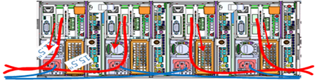
Similarly, the stand-alone F-series all flash nodes, in particular the 1RU F600 and F200 nodes, also have a similar density of cabling per rack unit:
Cabling Component | Medium | Cable Quantity per |
Back-end network | 10 or 40 Gb Ethernet or QDR Infiniband | 2 |
Front-end network | 10 or 40Gb Ethernet | 2 |
Management interface | 1Gb Ethernet | 1 |
Serial console | DB9 RS 232 | 1 |
Power cord | 110V or 220V AC power | 2 |
Total |
| 8 |
Consistent and meticulous cable labeling and management is particularly important in large clusters. PowerScale chassis that employ both front and back-end Ethernet networks can include up to 20 Ethernet connections per 4RU chassis.
In each node’s compute module, there are two PCI slots for the Ethernet cards (NICs). Viewed from the rear of the chassis, in each node the right hand slot (HBA Slot 0) houses the NIC for the front-end network, and the left hand slot (HBA Slot 1) houses the NIC for the front-end network. There is also a separate built-in 1Gb Ethernet port on each node for cluster management traffic.
While there is no requirement that node 1 aligns with port 1 on each of the back-end switches, it can certainly make cluster and switch management and troubleshooting considerably simpler. Even if exact port alignment is not possible, with large clusters, ensure that the cables are clearly labeled and connected to similar port regions on the back-end switches.
PowerScale nodes and the drives they contain have identifying LED lights to indicate when a component has failed and to allow proactive identification of resources. You can use the ‘isi led’ CLI command to illuminate specific node and drive indicator lights, as needed, to aid in identification.
Drive repair times depend on a variety of factors:
- OneFS release (determines Job Engine version and how efficiently it operates)
- System hardware (determines drive types, amount of CPU, RAM, and so on)
- Filesystem: Amount of data, data composition (lots of small vs large files), protection, tunables, and so on.
- Load on the cluster during the drive failure
A useful method to estimate future FlexProtect runtime is to use old repair runtimes as a guide, if available.
The drives in the PowerScale chassis-based platforms have a bay-grid nomenclature, where A-E indicates each of the sleds and 0-6 would point to the drive position in the sled. The drive closest to the front is 0, whereas the drive closest to the back is 2/3/5, depending on the drive sled type.
When it comes to updating and refreshing hardware in a large cluster, swapping nodes can be a lengthy process of somewhat unpredictable duration. Data has to be evacuated from each old node during the Smartfail process prior to its removal, and restriped and balanced across the new hardware’s drives. During this time there will also be potentially impactful group changes as new nodes are added and the old ones removed.
However, if replacing an entire node-pool as part of a tech refresh, a SmartPools filepool policy can be crafted to migrate the data to another nodepool across the back-end network. When complete, the nodes can then be Smartfailed out, which should progress swiftly because they are now empty.
If multiple nodes are Smartfailed simultaneously, at the final stage of the process the node remove is serialized with around 60 seconds pause between each. The Smartfail job places the selected nodes in read-only mode while it copies the protection stripes to the cluster’s free space. Using SmartPools to evacuate data from a node or set of nodes in preparation to remove them is generally a good idea, and is usually a relatively fast process.
Another efficient approach can often be to swap drives out into new chassis. In addition to being considerably faster, the drive swapping process focuses the disruption on a single whole cluster down event. Estimating the time to complete a drive swap, or ‘disk tango’ process, is simpler and more accurate and can typically be completed in a single maintenance window.
With PowerScale chassis-based platforms, such as the H700 and A300, the available hardware ‘tango’ options are expanded and simplified. Given the modular design of these platforms, the compute and chassis tango strategies typically replace the disk tango:
Replacement Strategy | Component | PowerScale F-series | Chassis-based Nodes | Description |
Disk tango | Drives / drive sleds | x | x | Swapping out data drives or drive sleds |
Compute tango | Chassis Compute modules |
| x | Rather than swapping out the twenty drive sleds in a chassis, it’s usually cleaner to exchange the four compute modules |
Chassis tango | 4RU Chassis |
| x | Typically only required if there’s an issue with the chassis mid-plane. |
Note that any of the above ‘tango’ procedures should only be executed under the recommendation and supervision of Dell support.
Author: Nick Trimbee

Address your Security Challenges with Zero Trust Model on Dell PowerScale
Mon, 03 Oct 2022 16:39:01 -0000
|Read Time: 0 minutes
Dell PowerScale, the world’s most secure NAS storage array[1], continues to evolve its already rich security capabilities with the recent introduction of External Key Manager for Data-at-Rest-Encryption, enhancements to the STIG security profile, and support for UEFI Secure Boot across PowerScale platforms.
Our next release of PowerScale OneFS adds new security features that include software-based firewall functionality, multi-factor authentication with support for CAC/PIV, SSO for administrative WebUI, and FIPS-compliant data in flight.
As the PowerScale security feature set continues to advance, meeting the highest level of federal compliance is paramount to support industry and federal security standards. We are excited to announce that our scheduled verification by the Department of Defense Information Network (DISA) for inclusion on the DoD Approved Product List will begin in March 2023. For more information, see the DISA schedule here.
Moreover, OneFS will embrace the move to IPv6-only networks with support for USGv6-r1, a critical network standard applicable to hundreds of federal agencies and to the most security-conscious enterprises, including the DoD. Refreshed Common Criteria certification activities are underway and will provide a highly regarded international and enterprise-focused complement to other standards being supported.
We believe that implementing the zero trust model is the best foundation for building a robust security framework for PowerScale. This model and its principles are discussed below.
Supercharge Dell PowerScale security with the zero trust model
In the age of digital transformation, multiple cloud providers, and remote employees, the confines of the traditional data center are not enough to provide the highest levels of security. In the traditional sense, security was considered placing your devices in an imaginary “bubble.” The thought was that as long as devices were in the protected “bubble,” security was already accounted for through firewalls on the perimeter. However, the age-old concept of an organization’s security depending on the firewall is no longer relevant and is the easiest for a malicious party to attack.

Now that the data center is not confined to an area, the security framework must evolve, transform, and adapt. For example, although firewalls are still critical to network infrastructure, security must surpass just a firewall and security devices.
Why is data security important?
Although this seems like an easy question, it’s essential to understand the value of what is being protected. Traditionally, an organization’s most valuable assets were its infrastructure, including a building and the assets required to produce its goods. However, in the age of Digital Transformation, organizations have realized that the most critical asset is their data.
Why a zero trust model?
Because data is an organization’s most valuable asset, protecting the data is paramount. And how do we protect this data in the modern environment without data center confines? Enter the zero trust model!
Although Forrester Research first defined zero trust architecture in 2010, it has recently received more attention with the ever-changing security environment leading to a focus on cybersecurity. The zero trust architecture is a general model and must be refined for a specific implementation. For example, in September 2019, the National Institute of Standards and Technology (NIST) introduced its concept of Zero Trust Architecture. As a result, the White House has also published an Executive Order on Improving the Nation’s Cybersecurity, including zero trust initiatives.
In a zero trust architecture, all devices must be validated and authenticated. The concept applies to all devices and hosts, ensuring that none are trusted until proven otherwise. In essence, the model adheres to a “never trust, always verify” policy for all devices.
NIST Special Publication 800-207 Zero Trust Architecture states that a zero trust model is architected with the following design tenets:
- All data sources and computing services are considered resources.
- All communication is secured regardless of network location.
- Access to individual enterprise resources is granted on a per session basis.
- Access to resources is determined by dynamic policy—including the observable state of client identity, application/service, and the requesting asset—and may include other behavioral and environmental attributes.
- The enterprise monitors and measures the integrity and security posture of all owned and associated assets.
- All resource authentication and authorization are dynamic and strictly enforced before access is allowed.
- The enterprise collects as much information as possible related to the current state of assets, network infrastructure, and communications and uses it to improve its security posture.

PowerScale OneFS follows the zero trust model
The PowerScale family of scale-out NAS solutions includes all-flash, hybrid, and archive storage nodes that can be deployed across the entire enterprise – from the edge, to core, and the cloud, to handle the most demanding file-based workloads. PowerScale OneFS combines the three layers of storage architecture—file system, volume manager, and data protection—into a scale-out NAS cluster. Dell Technologies follows the NIST Cybersecurity Framework to apply zero trust principles on a PowerScale cluster. The NIST Framework identifies five principles: identify, protect, detect, respond, and recover. Combining the framework from the NIST CSF and the data model provides the basis for the PowerScale zero trust architecture in five key stages, as shown in the following figure.
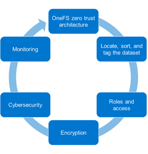
Let’s look at each of these stages and what Dell Technologies tools can be used to implement them.
1. Locate, sort, and tag the dataset
To secure an asset, the first step is to identify the asset. In our case, it is data. To secure a dataset, it must first be located, sorted, and tagged to secure it effectively. This can be an onerous process depending on the number of datasets and their size. We recommend using the Superna Eyeglass Search and Recover feature to understand your unstructured data and to provide insights through a single pane of glass, as shown in the following image. For more information, see the Eyeglass Search and Recover Product Overview.
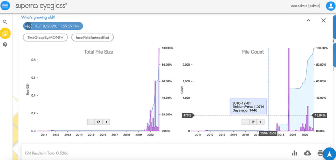
2. Roles and access
Once we know the data we are securing, the next step is to associate roles to the indexed data. The role-specific administrators and users only have access to a subset of the data necessary for their responsibilities. PowerScale OneFS allows system access to be limited to an administrative role through Role-Based Access Control (RBAC). As a best practice, assign only the minimum required privileges to each administrator as a baseline. In the future, more privileges can be added as needed. For more information, see PowerScale OneFS Authentication, Identity Management, and Authorization.
3. Encryption
For the next step in deploying the zero trust model, use encryption to protect the data from theft and man-in-the-middle attacks.
Data at Rest Encryption
PowerScale OneFS provides Data at Rest Encryption (D@RE) using self-encrypting drives (SEDs), allowing data to be encrypted during writes and decrypted during reads with a 256-bit AES encryption key, referred to as the data encryption key (DEK). Further, OneFS wraps the DEK for each SED in an authentication key (AK). Next, the AKs for each drive are placed in a key manager (KM) that is stored securely in an encrypted database, the key manager database (KMDB). Next, the KMDB is encrypted with a 256-bit master key (MK). Finally, the 256-bit master key is stored external to the PowerScale cluster using a key management interoperability protocol (KMIP)-compliant key manager server, as shown in the following figure. For more information, see PowerScale Data at Rest Encryption.
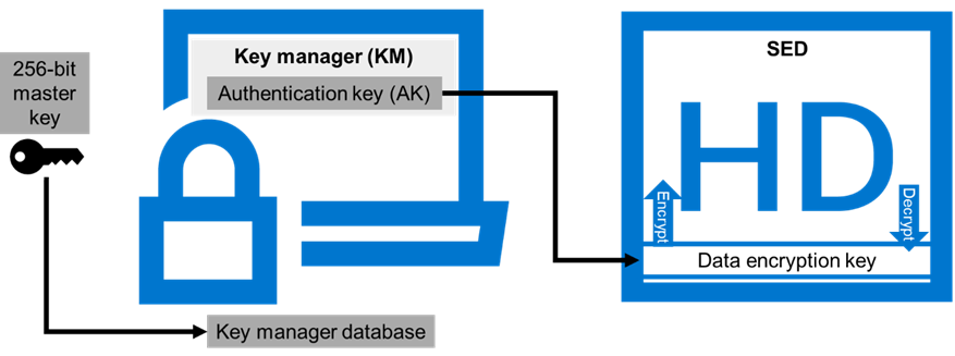
Data in flight encryption
Data in flight is encrypted using SMB3 and NFS v4.1 protocols. SMB encryption can be used by clients that support SMB3 encryption, including Windows Server 2012, 2012 R2, 2016, Windows 10, and 11. Although SMB supports encryption natively, NFS requires additional Kerberos authentication to encrypt data in flight. OneFS Release 9.3.0.0 supports NFS v4.1, allowing Kerberos support to encrypt traffic between the client and the PowerScale cluster.
Once the protocol access is encrypted, the next step is encrypting data replication. OneFS supports over-the-wire, end-to-end encryption for SyncIQ data replication, protecting and securing in-flight data between clusters. For more information about these features, see the following:
- PowerScale: Solution Design and Considerations for SMB Environments
- PowerScale OneFS NFS Design Considerations and Best Practices
- PowerScale SyncIQ: Architecture, Configuration, and Considerations
4. Cybersecurity
In an environment of ever-increasing cyber threats, cyber protection must be part of any security model. Superna Eyeglass Ransomware Defender for PowerScale provides cyber resiliency. It protects a PowerScale cluster by detecting attack events in real-time and recovering from cyber-attacks. Event triggers create an automated response with real-time access auditing, as shown in the following figure.
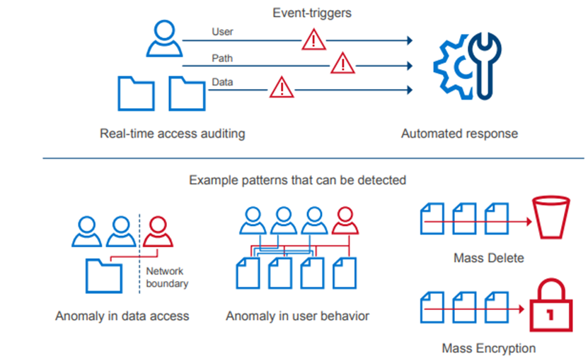
The Enterprise AirGap capability creates an isolated data copy in a cyber vault that is network isolated from the production environment, as shown in the following figure. For more about PowerScale Cyber Protection Solution, check out this comprehensive eBook.
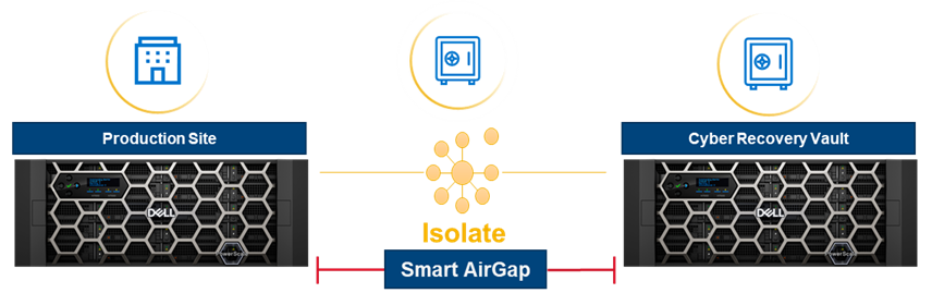
5. Monitoring
Monitoring is a critical component of applying a zero trust model. A PowerScale cluster should constantly be monitored through several tools for insights into cluster performance and tracking anomalies. Monitoring options for a PowerScale cluster include the following:
- Dell CloudIQ for proactive monitoring, machine learning, and predictive analytics.
- Superna Ransomware Defender for protecting a PowerScale cluster by detecting attack events in real-time and recovering from cyber-attacks. It also offers AirGap.
- PowerScale OneFS SDK to create custom applications specific to an organization. Uses the OneFS API to configure, manage, and monitor cluster functionality. The OneFS SDK provides greater visibility into a PowerScale cluster.
Conclusion
This blog introduces implementing the zero trust model on a PowerScale cluster. For additional details and applying a complete zero trust implementation, see the PowerScale Zero Trust Architecture section in the Dell PowerScale OneFS: Security Considerations white paper. You can also explore the other sections in this paper to learn more about all PowerScale security considerations.
Author: Aqib Kazi
[1] Based on Dell analysis comparing cybersecurity software capabilities offered for Dell PowerScale vs competitive products, September 2022.

PowerScale Security Baseline Checklist
Sat, 01 Oct 2022 23:21:56 -0000
|Read Time: 0 minutes
As a security best practice, a quarterly security review is recommended. Forming an aggressive security posture for a PowerScale cluster is composed of different facets that may not be applicable to every organization. An organization’s industry, clients, business, and IT administrative requirements determine what is applicable. To ensure an aggressive security posture for a PowerScale cluster, use the checklist in the following table as a baseline for security.
This table serves as a security baseline and must be adapted to specific organizational requirements. See the Dell PowerScale OneFS: Security Considerations white paper for a comprehensive explanation of the concepts in the table below.
Further, cluster security is not a single event. It is an ongoing process: Monitor this blog for updates. As new updates become available, this post will be updated. Consider implementing an organizational security review on a quarterly basis.
The items listed in the following checklist are not in order of importance or hierarchy but rather form an aggressive security posture as more features are implemented.
Table 1. PowerScale security baseline checklist
Security Feature | Configuration | Links | Complete (Y/N) | Notes |
Data at Rest Encryption | Implement external key manager with SEDs | PowerScale Data at Rest Encryption |
|
|
Data in flight encryption | Encrypt protocol communication and data replication | PowerScale: Solution Design and Considerations for SMB Environments PowerScale OneFS NFS Design Considerations and Best Practices PowerScale SyncIQ: Architecture, Configuration, and Considerations |
|
|
Role-based access control (RBACs) | Assign the lowest possible access required for each role | Dell PowerScale OneFS: Authentication, Identity Management, and Authorization |
|
|
Multi-factor authentication | Dell PowerScale OneFS: Authentication, Identity Management, and Authorization Disabling the WebUI and other non-essential services |
|
| |
Cybersecurity |
|
| ||
Monitoring | Monitor cluster activity | Dell CloudIQ - AIOps for Intelligent IT Infrastructure Insights |
|
|
Secure Boot | Configure PowerScale Secure Boot | See PowerScale Secure Boot section |
|
|
Auditing | Configure auditing | File System Auditing with Dell PowerScale and Dell Common Event Enabler |
|
|
Custom applications | Create a custom application for cluster monitoring |
|
| |
Perform a quarterly security review | Review all organizational security requirements and current implementation. Check this paper and checklist for updates Monitor security advisories for PowerScale: https://www.dell.com/support/security/en-us |
|
| |
General cluster security best practices
| See the Security best practices section in the Security Configuration Guide for the relevant release at OneFS Info Hubs |
|
| |
Login, authentication, and privileges best practices |
|
| ||
SNMP security best practices |
|
| ||
SSH security best practices |
|
| ||
Data-access protocols best practices |
|
| ||
Web interface security best practices |
|
| ||
Anti-Virus |
|
| ||
Author: Aqib Kazi

Distributed Media Workflows with PowerScale OneFS and Superna Golden Copy
Tue, 06 Sep 2022 20:46:32 -0000
|Read Time: 0 minutes
Object is the new core
Content creation workflows are increasingly distributed between multiple sites and cloud providers. Data orchestration has long been a key component in these workflows. With the extra complexity (and functionality) of multiple on-premises and cloud infrastructures, automated data orchestration is more crucial than ever.
There has been a subtle but significant shift in how media companies store and manage data. In the old way, file storage formed the “core” and data was eventually archived off to tape or object storage for long-term retention. The new way of managing data flips this paradigm. Object storage has become the new “core” with performant file storage at edge locations used for data processing and manipulation.
Various factors have influenced this shift. These factors include the ever-increasing volume of data involved in modern productions, the expanding role of public cloud providers (for whom object storage is the default), and media application support.
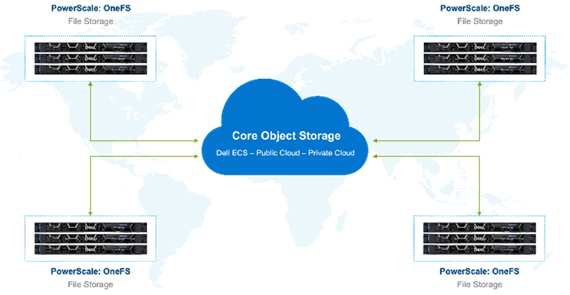
Figure 1. Global storage environment
With this shift in roles, new techniques for data orchestration become necessary. Data management vendors are reacting to these requirements for data movement and global file system solutions.
However, many of these solutions require data to be ingested and accessed through dedicated proprietary gateways. Often this gateway approach means that the data is now inaccessible using the native S3 API.
PowerScale OneFS and Superna Golden Copy provide a way of orchestrating data between file and object that retains the best qualities of both types of storage. Data is available to be accessed on both the performant edge (PowerScale) and the object core (ECS or public cloud) with no lock in at either end.
Further, Superna Golden Copy is directly integrated with the PowerScale OneFS API. The OneFS snapshot change list is used for immediate incremental data moves. Filesystem metadata is preserved in S3 tags.
Golden Copy and OneFS are a solution built for seamless movement of data between locations, file system, and object storage. File structure and metadata are preserved.
Right tool for the job
Data that originates on object storage needs to be accessible natively by systems that can speak object APIs. Also, some subset of data needs to be moved to file storage for further processing. Production data that originates on file storage similarly needs native access. That file data will need to be moved to object storage for long-term retention and to make it accessible to globally distributed resources.
Content creation workflows are spread across multiple teams working in many locations. Multisite productions require distributed storage ecosystems that can span geographies. This architecture is well suited to a core of object storage as the “central source of truth”. Pools of highly performant file storage serve teams in their various global locations.
The Golden Copy GraphQL API allows external systems to control, configure, and monitor Golden Copy jobs. This type of API-based data orchestration is essential to the complex global pipelines of content creators. Manually moving large amounts of data is untenable. Schedule-based movement of data aligns well with some content creation workflows; other workflows require more ad hoc data movement.
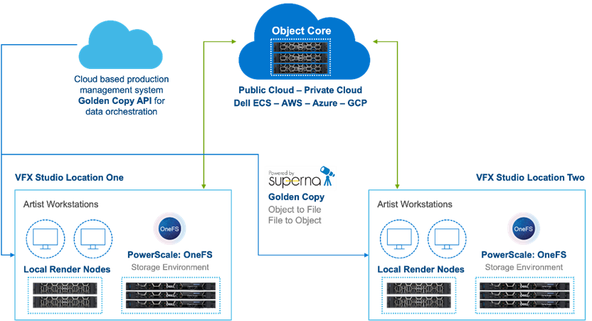
Figure 2. Object Core with GoldenCopy and PowerScale
A large ecosystem of production management tools, such as Autodesk Shotgrid, exist for managing global teams. These tools are excellent for managing projects, but do not typically include dedicated data movers. Data movement can be particularly challenging when large amounts of media need to be shifted between object and file.
Production asset management can trigger data moves with Golden Copy based on metadata changes to a production or scene. This kind of API and metadata driven data orchestration fits in the MovieLabs 2030 vision for software-defined workflows for content creation. This topic is covered in some detail for tiering within a OneFS file system in the paper: A Metadata Driven Approach to On Demand Tiering.
For more information about using PowerScale OneFS together with Superna GoldenCopy, see my full white paper PowerScale OneFS: Distributed Media Workflows.
Author: Gregory Shiff

Artificial Intelligence for IT operations (AIOps) in PowerScale Performance Prediction
Tue, 06 Sep 2022 18:14:53 -0000
|Read Time: 0 minutes
AI is a fancy and hot topic in recent years. A common question from our customers is ‘How can AI help the day-to-day operation and management of PowerScale?’ It’s a very interesting question, because although AI can help realize so many possibilities, we still don’t have that many implementations of it in IT infrastructure.
But, we finally have something that is very inspiring. Here is what we have achieved as proof of concept in our lab with the support of AI Dynamics, a professional AI platform company.
Challenges for IT operations and opportunities for AIOps
With the increase in complexity of IT infrastructure comes the increase in the amount of data produced by these systems, Real-time performance logs, usage reports, audits, and other metadata can add up to gigabytes or terabytes a day. It is a big challenge for the IT department to analyze this data and to extract proactive predictions, such as IT infrastructure performance issues and their bottlenecks.
AIOps is the methodology to address these challenges. The term ‘AIOps’ refers to the use of artificial intelligence (AI), specifically machine learning (ML) techniques, to ingest, analyze, and learn from large volumes of data from every corner of the IT environment. The goal of AIOps is to allow IT departments to manage their assets and tackle performance challenges proactively, in real-time (or better), before they become system-wide issues.
PowerScale key performance prediction using AIOps
Overview
In this solution, we identify NFS latency as the PowerScale performance indicator that customers would like to see predictive reporting about. The goal of the AI model is to study historical system activity and predict the NFS latency at five-minute intervals for four hours in the future. A traditional software system can use these predictions to alert users of a potential performance bottleneck based on the user’s specified latency threshold level and spike duration. In the future, AI models can be built that help diagnose the source of these issues so that both an alert and a best-recommended solution can be reported to the user.
The whole training process involves the following three steps (I’ll explain the details in the following sections):
- Data preparation – to get the raw data and extract the useful features as the input for training and validation
- Training the model – to pick up a proper AI architecture and tune the parameters for accuracy
- Model validation – to validate the AI model based on the data set obtained from the training
Data preparation
The raw performance data is collected through Dell Secure Remote Services (SRS) from 12 different all-flash PowerScale clusters from an electronic design automation (EDA) customer each week. We identify and extract 26 performance key metrics from the raw data, most of which are logged and updated every five minutes. AI Dynamics NeoPulse is used to extract some additional fields (such as the day of the week and time of day from the UNIX timestamp fields) to allow the model to make better predictions. Each week new data was collected from the PowerScale cluster to increase the size of the training dataset and to improve the AI model. During every training run, we also withheld 10% of the data, which we used to test the AI model in the testing phase. This is separate from the 10% of training data withheld for validation.
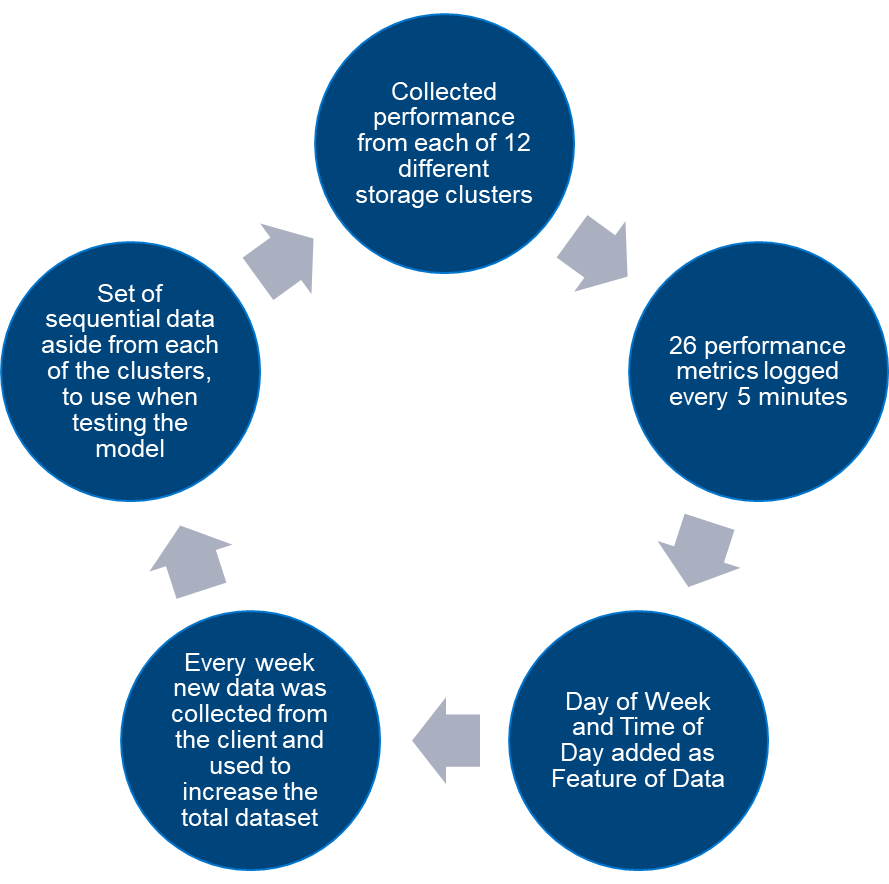
Figure 1. Data preparation process
Training the model
Over a period of two months, more than 50 different AI models were trained using a variety of different time series architectures, varying model architecture parameters, hyperparameters, and data engineering techniques to maximize performance, without overfitting to existing data. When these training pipelines were created in NeoPulse, they could easily be reused as new data arrived from the client each week, to rerun training and testing in order to quantify the performance of the model.
At the end of the two-month period, we had built a model that could predict whether this one performance metric (NFS3 latency) would be above a threshold of 10ms, correctly for 70% of each one of the next 48 five-minute intervals (four hours total).
Model validation
In the data preparation phase, we withheld 10% of the total data set to be used for AI model validation and testing. With the current AI model, end-users can easily configure the threshold of the latency as they want. In this case, we validated the model at 10ms and 15ms thresholds latency. The model can correctly identify over 70% of 10ms latency spikes and 60% of 15ms latency spikes over the entire ensuing four-hour period.
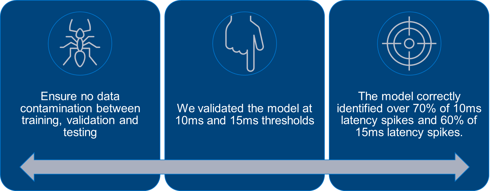
Figure 2. Model Validation
Results
In this solution, we used NFS latency from PowerScale as the indicator to be predicted. The AI model uses the performance data from the previous four hours to predict the trends and spikes of NFS latency in the next four hours. If the software identifies a five-minute period when a >10ms latency spike would occur more than 70% of the time, it will trigger a configurable alert to the user.
The following diagram shows an example. At 8:55 a.m., the AI model predicts the NFS latency from 8:55 a.m. to 12:55 p.m., based on the input of performance data from 4:55 a.m. to 8:55 a.m. The AI model makes predictions for each five-minute period over the prediction duration. The model predicts a few isolated spikes in latency, with a large consecutive cluster of high latency between around 12 p.m. and 12:55 p.m. A software system can use this prediction to alert the user about the expected increase in latency, giving them over three hours to get ahead of the problem and reduce the server load. In the graph, the dotted line shows the AI model’s prediction, whereas the solid line shows actual performance.
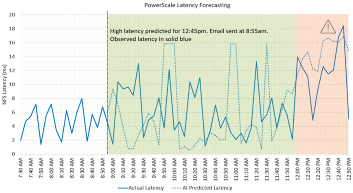
Figure 3. Dell PowerScale NFS Latency Forecasting
To sum up, the solution achieved the following:
- By using the previous four hours of PowerScale performance data, the solution can forecast the next four hours of any specified metric.
- For NFS3 latency, the solution was benchmarked as correctly identifying periods when latency would be above 10ms 70% of the time.
- The data and model training pipelines created for this task can easily be adapted to predict other performance metrics, such as NFS throughput spikes, SMB latency spikes, and so on.
- The AI learns to improve its predictions week by week as it adapts to each customer’s nuanced usage patterns, creating customized models for each customer’s idiosyncratic workload profiles.
Conclusion
AIOps introduces the intelligence needed to manage the complexity of modern IT environments. The NeoPulse platform from AI Dynamics makes AIOps easy to implement. In an all-flash configuration of Dell PowerScale clusters, performance is one of the key considerations. Hundreds and thousands of performance logs are generated every day and it is very easy for AIOps to consume the existing logs and provide insight into potential performance bottlenecks. Dell servers with GPUs are great platforms for performing training and inference, for not just this model but for any other new AI challenge the company wishes to tackle, across dozens of problem types.
For additional details about our testing, see the white paper Key Performance Prediction using Artificial Intelligence for IT operations (AIOps).
Author: Vincent Shen

Network Design for PowerScale CSI
Tue, 23 Aug 2022 17:00:45 -0000
|Read Time: 0 minutes
Network connectivity is an essential part of any infrastructure architecture. When it comes to how Kubernetes connects to PowerScale, there are several options to configure the Container Storage Interface (CSI). In this post, we will cover the concepts and configuration you can implement.
The story starts with CSI plugin architecture.
CSI plugins
Like all other Dell storage CSI, PowerScale CSI follows the Kubernetes CSI standard by implementing functions in two components.
- CSI controller plugin
- CSI node plugin
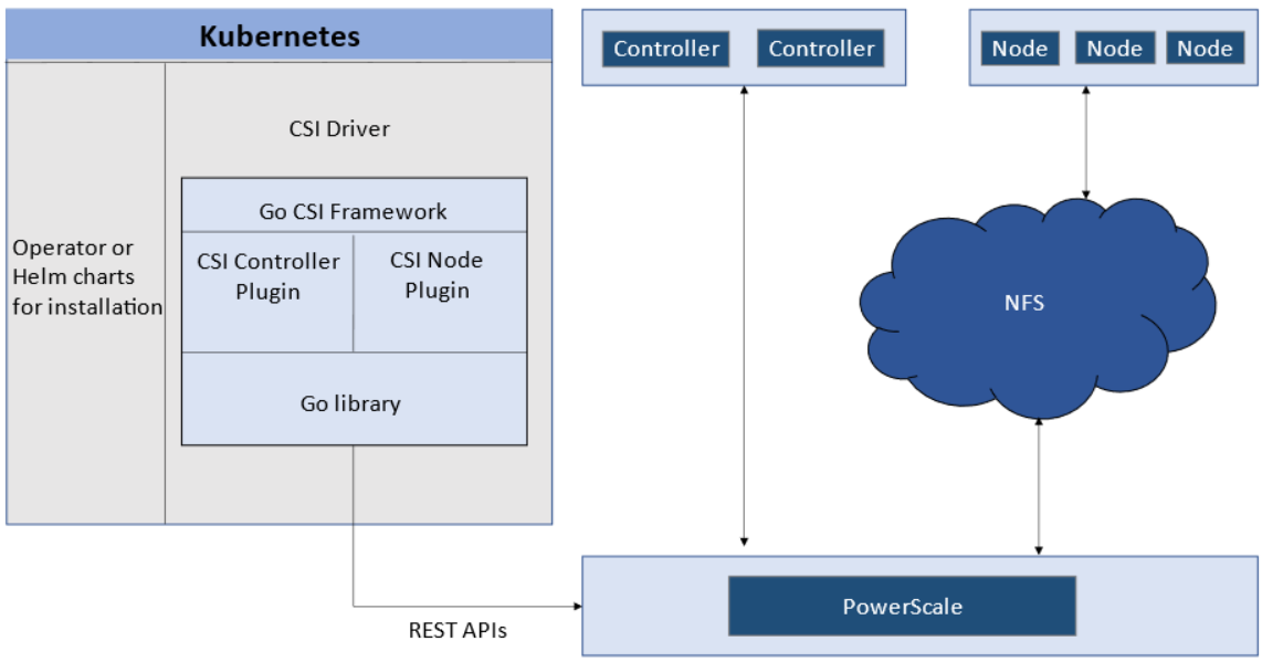
The CSI controller plugin is deployed as a Kubernetes Deployment, typically with two or three replicas for high-availability, with only one instance acting as a leader. The controller is responsible for communicating with PowerScale, using Platform API to manage volumes (to PowerScale it’s to create/delete directories, NFS exports, and quotas), to update the NFS client list when a Pod moves, and so on.
A CSI node plugin is a Kubernetes DaemonSet, running on all nodes by default. It’s responsible for mounting the NFS export from PowerScale, to map the NFS mount path to a Pod as persistent storage, so that applications and users in the Pod can access the data on PowerScale.
Roles, privileges, and access zone
Because CSI needs to access both PAPI (PowerScale Platform API) and NFS data, a single user role typically isn’t secure enough: the role for PAPI access will need more privileges than normal users.
According to the PowerScale CSI manual, CSI requires a user that has the following privileges to perform all CSI functions:
Privilege | Type |
ISI_PRIV_LOGIN_PAPI | Read Only |
ISI_PRIV_NFS | Read Write |
ISI_PRIV_QUOTA | Read Write |
ISI_PRIV_SNAPSHOT | Read Write |
ISI_PRIV_IFS_RESTORE | Read Only |
ISI_PRIV_NS_IFS_ACCESS | Read Only |
ISI_PRIV_IFS_BACKUP | Read Only |
Among these privileges, ISI_PRIV_SNAPSHOT and ISI_PRIV_QUOTA are only available in the System zone. And this complicates things a bit. To fully utilize these CSI features, such as volume snapshot, volume clone, and volume capacity management, you have to allow the CSI to be able to access the PowerScale System zone. If you enable the CSM for replication, the user needs the ISI_PRIV_SYNCIQ privilege, which is a System-zone privilege too.
By contrast, there isn’t any specific role requirement for applications/users in Kubernetes to access data: the data is shared by the normal NFS protocol. As long as they have the right ACL to access the files, they are good. For this data accessing requirement, a non-system zone is suitable and recommended.
These two access zones are defined in different places in CSI configuration files:
- The PAPI access zone name (FQDN) needs to be set in the secret yaml file as “endpoint”, for example “f200.isilon.com”.
- The data access zone name (FQDN) needs to be set in the storageclass yaml file as “AzServiceIP”, for example “openshift-data.isilon.com”.
If an admin really cannot expose their System zone to the Kubernetes cluster, they have to disable the snapshot and quota features in the CSI installation configuration file (values.yaml). In this way, the PAPI access zone can be a non-System access zone.
The following diagram shows how the Kubernetes cluster connects to PowerScale access zones.
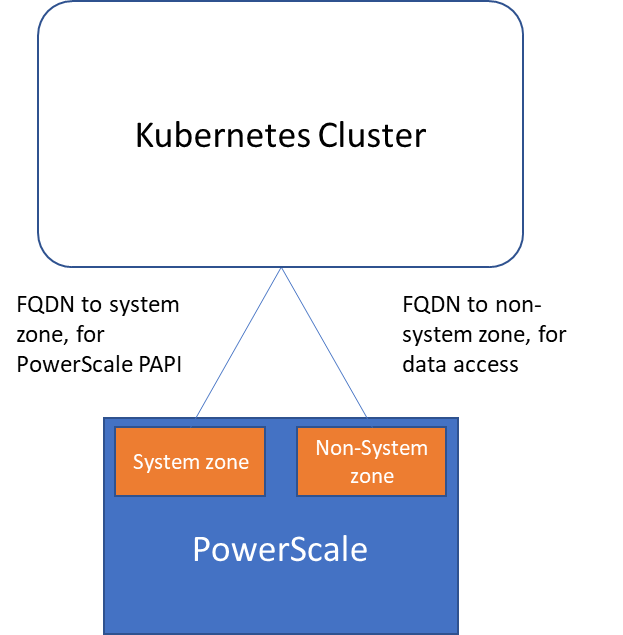
Network
Normally a Kubernetes cluster comes with many networks: a pod inter-communication network, a cluster service network, and so on. Luckily, the PowerScale network doesn’t have to join any of them. The CSI pods can access a host’s network directly, without going through the Kubernetes internal network. This also has the advantage of providing a dedicated high-performance network for data transfer.
For example, on a Kubernetes host, there are two NICs: IP 192.168.1.x and 172.24.1.x. NIC 192.168.1.x is used for Kubernetes, and is aligned with its hostname. NIC 172.24.1.x isn’t managed by Kubernetes. In this case, we can use NIC 172.24.1.x for data transfer between Kubernetes hosts and PowerScale.
Because by default, the CSI driver will use the IP that is aligned with its hostname, to let CSI recognize the second NIC 172.24.1.x, we have explicitly set the IP range in “allowedNetworks” in the values.yaml file in the CSI driver installation. For example:
allowedNetworks: [172.24.1.0/24]
Also, in this network configuration, it’s unlikely that the Kubernetes internal DNS can resolve the PowerScale FQDN. So, we also have to make sure the “dnsPolicy” has been set to “ClusterFirstWithHostNet” in the values.yaml file. With this dnsPolicy, the CSI pods will reach the DNS server in /etc/resolv.conf in the host OS, not the internal DNS server of Kubernetes.
The following diagram shows the configuration mentioned above:
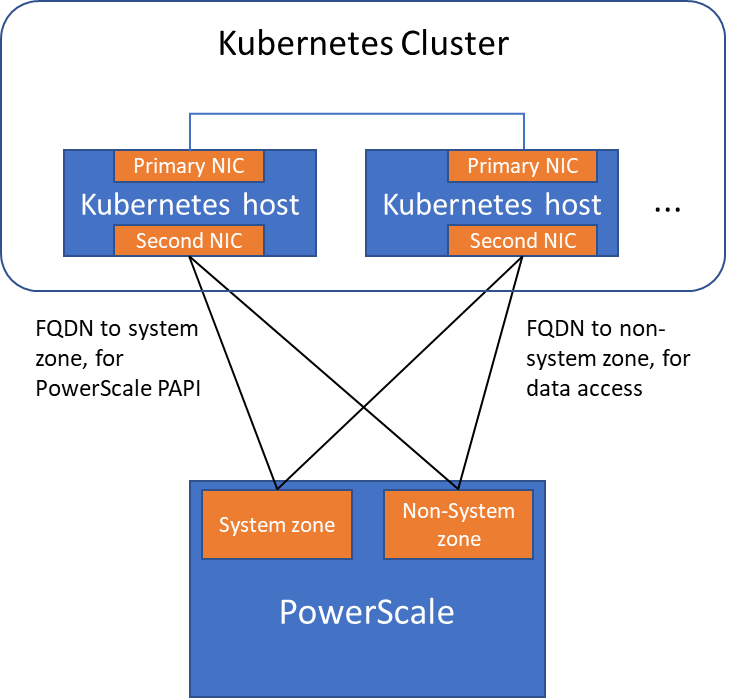
Please note that the “allowedNetworks” setting only affects the data access zone, and not the PAPI access zone. In fact, CSI just uses this parameter to decide which host IP should be set as the NFS client IP on the PowerScale side.
Regarding the network routing, CSI simply follows the OS route configuration. Because of that, if we want the PAPI access zone to go through the primary NIC (192.168.1.x), and have the data access zone to go through the second NIC (172.24.1.x), we have to change the route configuration of the Kubernetes host, not this parameter.
Hopefully this blog helps you understand the network configuration for PowerScale CSI better. Stay tuned for more information on Dell Containers & Storage!
Authors: Sean Zhan, Florian Coulombel

Disabling the WebUI and other Non-essential Services
Mon, 25 Jul 2022 13:43:38 -0000
|Read Time: 0 minutes
In today's security environment, organizations must adhere to governance security requirements, including disabling specific HTTP services.
OneFS release 9.4.0.0 has introduced an option to disable non-essential cluster services selectively rather than disabling all HTTP services. Disabling selectively allows administrators to determine which services are necessary. Disabling the services allows other essential services on the cluster to continue to run. You can disable the following non-essential services:
- PowerScaleUI (WebUI)
- Platform-API-External
- Rest Access to Namespace (RAN)
- RemoteService
Each of these services can be disabled independently and has no impact on other HTTP-based data services. The services can be disabled through the CLI or API with the ISI_PRIV_HTTP privilege. To manage the non-essential services from the CLI, use the isi http services list command to list the services. Use the isi http services view and isi http services modify commands to view and modify the services. The impact of disabling each of the services is listed in the following table.
HTTP services impacts
Service | Impacts |
PowerScaleUI | The WebUI is entirely disabled. Attempting to access the WebUI displays Service Unavailable. Please contact Administrator. |
Platform-API-External | Disabling the Platform-API-External service does not impact the Platform-API-Internal service of the cluster. The Platform-API-Internal services continue to function, even if the Platform-API-External service is disabled. However, if the Platform-API-External service is disabled, the WebUI is also disabled at that time, because the WebUI uses the Platform-API-External service. |
RAN (Remote Access to Namespace) | If RAN is disabled, use of the Remote File Browser UI component is restricted in the Remote File Browser and the File System Explorer. |
RemoteService | If RemoteService is disabled, the remote support UI and the InProduct Activation UI components are restricted. |
To disable the WebUI, use the following command:
isi http services modify --service-id=PowerScaleUI --enabled=false
Author: Aqib Kazi

Dell PowerScale for Google Cloud New Release Available
Fri, 22 Jul 2022 17:58:28 -0000
|Read Time: 0 minutes
PowerScale for Google Cloud provides the native-cloud experience of file services with high performance. It is a scalable file service that provides high-speed file access over multiple protocols, including SMB, NFS, and HDFS. PowerScale for Google Cloud enables customers to run their cloud workloads on the PowerScale scale-out NAS storage system. The following figure shows the architecture of PowerScale for Google Cloud. The three main parts are the Dell Technologies partner data center, the Dell Technologies Google Cloud organization (isiloncloud.com), and the customer’s Google Cloud organization (for example, customer-a.com and customer-b.com).
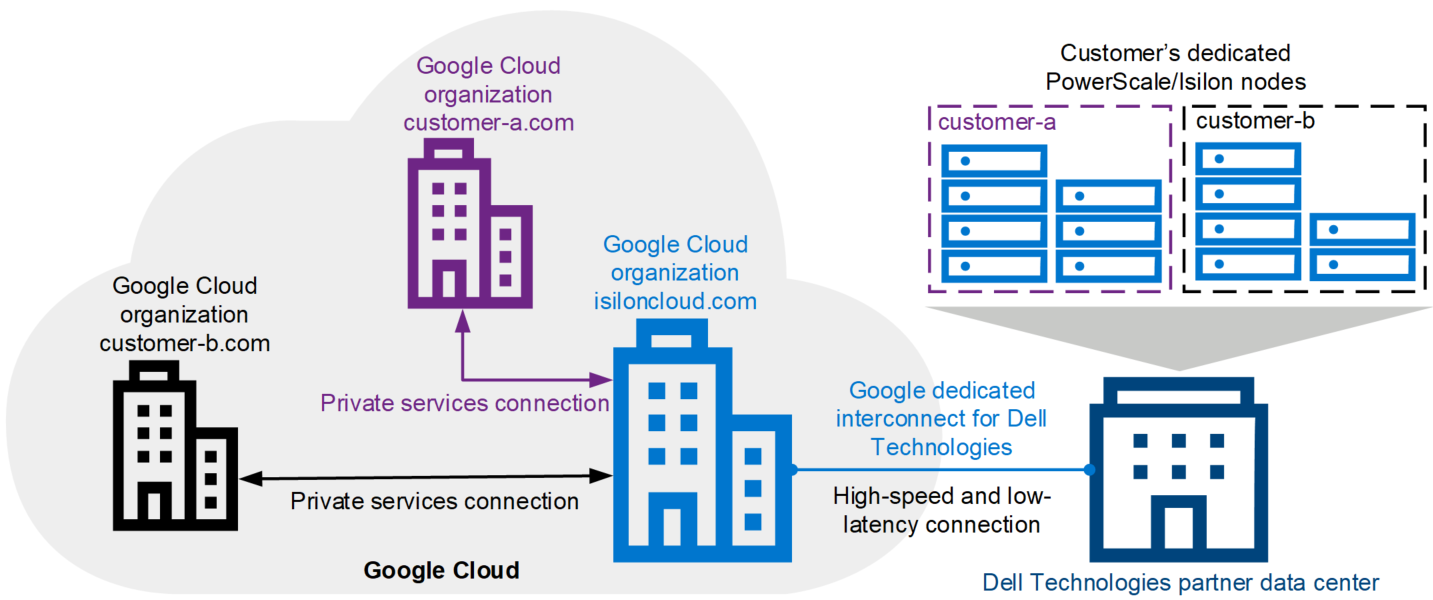
PowerScale for Google Cloud: a new release
We proudly released a new version of PowerScale for Google Cloud on July 8, 2022. It provides the following key features and enhancements:
More flexible configuration to choose
In the previous version of PowerScale for Google Cloud, only several pre-defined node tiers were available. With the latest version, you can purchase all PowerScale node types to fit your business needs and accelerate your native-cloud file service experience.
New location available in EMEA region
In the previous version, the supported regions include North America and APJ (Australia and Singapore). We are now adding the EMEA region, which includes London, Frankfurt, Paris, and Warsaw.
Google Cloud VMware Engine (GCVE) Certification
PowerScale for Google Cloud is now certified to support GCVE. GCVE guest VMs can connect to PowerScale for Google Cloud file services to fully leverage PowerScale cluster storage. We’ll be taking a deeper look at the details in blog articles in the next few weeks.
Want to know more about the powerful cloud file service solution? Just click these links:
- PowerScale for Google Cloud Interactive Demo
- PowerScale for Google Cloud white paper
- PowerScale for Google Cloud User Documentation
Resources
Author: Lieven Lin

Data Access in OneFS - Part 2: Introduction to OneFS Access Tokens
Fri, 01 Jul 2022 14:15:16 -0000
|Read Time: 0 minutes
Recap
In the previous blog, we introduced the OneFS file permission basics, including:
1. OneFS file permission is only in one of the following states:
- POSIX mode bits - authoritative with a synthetic ACL
- OneFS ACL - authoritative with approximate POSIX mode bits
2. No matter the OneFS file permission state, the on-disk identity for a file is always a UID, a GID, or an SID. The name of a user or group is for display only.
3. When OneFS receives a user access request, it generates an access token for the user and compares the token to the file permissions based on UID/GID/SID.
Therefore, in this blog, we will explain what UID/GID/SID is, and will explain what a OneFS access token is. Now, let’s start by looking at UID/GID/SIDs.
UID/GID and SID
In our daily life, we are usually familiar with a username or a group name, which stands for a user or a group. In a NAS system, we use UID, GID, and SID to identify a user or a group, then the NAS system will resolve the UID, GID, and SID into a related username or group name.
The UID/GID is usually used in a UNIX environment to identify users/groups with a positive integer assigned. The UID/GID is usually provided by the local operating system and LDAP server.
The SID is usually used in a Windows environment to identify users/groups. The SID is usually provided by the local operating system and Active Directory (AD). The SID is written in the format:
(SID)-(revision level)-(identifier-authority)-(subauthority1)-(subauthority2)-(etc)
for example:
S-1-5-21-1004336348-1177238915-682003330-512
For more information about SIDs, see the Microsoft article: What Are Security Identifiers?.
OneFS access token
In OneFS, information about users and groups is managed and stored in different authentication providers, including UID/GID and SID information, and user group membership information. OneFS can add multiple types of authentication provider, including:
- Active Directory (AD)
- Lightweight Directory Access Protocol (LDAP) servers
- NIS
- File provider
- Local provider
OneFS retrieves a user’s identity (UID/GID/SID) and group memberships from the above authentication providers. Assuming that we have a user named Joe, OneFS tries to resolve Joe’s UID/GID and group memberships from LDAP, NIS, file provider, and Local provider. Meanwhile, it also tries to resolve Joe’s SID and group memberships from AD, file provider, or local provider.
- If neither UID/GID nor SID can be found in any of the authentication providers, the user does not exist. User access may be denied or be mapped to the ‘nobody’ user, depending on your protocol.
- If only a UID/GID can be found or only a SID can be found, OneFS generates a fake UID or SID for the user.
It is not always the case that OneFS needs to resolve a user from username to UID/GID/SID. It is also possible that OneFS needs to resolve a user in reverse: that is, resolve a UID to its related username. This usually occurs when using NFSv3. When OneFS gets all UID/GID/SID information for a user, it will maintain the identity relationship in a local database, which records the UID <--> SID and GID <-->SID mapping, also known as the ID mapping function in OneFS.
Now, you should have an overall idea about how OneFS maintains the important UID/GID/SID information, and how to retrieve this information as needed.
Next, let’s see how OneFS can determine whether different usernames in different authentication types are actually the same real user. For example: how can we tell if the Joe in AD and the joe_f in LDAP is same guy or not? If they are the same, OneFS needs to ensure that they have the same access to the same file, even with different protocols.
That is the magic of the OneFS user mapping function. The default user mapping rule maps users together that have the same usernames in different authentication providers. For example, the Joe in AD and the Joe in LDAP will be considered the same user. You must create user mapping rules if a real user has different names in different authentication providers. The user mapping rule can have different operators, to provide more flexible management between different usernames in different authentication providers. The operators could be Append, Insert, Replace, Remove Groups, Join. See OneFS user mapping operators for more details. We just need to remember that the user mapping is just a function to determine if the user information in an authentication provider should be used when generating an access token.
Although it is easy to confuse user mapping with ID mapping, user mapping is the process of identifying users across authentication providers for the purpose of token generation. After the token is generated, the mappings of SID<-->UID are placed in the ID mapping database.
Finally, OneFS must choose an authoritative identity (that is, an On-Disk Identity) from the collected/generated UID/GID/SID for the user, which will be stored on disk and is used when the file is created or when ownership of file changes, impacting the file permissions.
In a single protocol environment, determining the On-Disk Identity is simple because Windows uses SIDs and Linux uses UIDs. However, in a multi-protocol environment, only one identity is stored, and the challenge is determining which one is stored. By default, the policy configured for on-disk identity is Native mode. Native mode is the best option for most environments. OneFS selects the real value between the SID and UID/GID. If both the SID and UID/GID are real values, OneFS selects UID/GID. Please note that this blog series is based on the default policy setting.
Now you should have an overall understanding of user mapping, ID mapping, and on-disk identity. These are the key concepts when understanding user access tokens and doing troubleshooting. Finally, let’s see what an access token contains.
You can view a user’s access token by using the command isi auth mapping token <username> in OneFS. Here is an example of Joe’s access token:
vonefs-aima-1# isi auth mapping token Joe User Name: Joe UID: 2001 SID: S-1-5-21-1137111906-3057660394-507681705-1002 On Disk: 2001 ZID: 1 Zone: System Privileges: - Primary Group Name: Market GID: 2003 SID: S-1-5-21-1137111906-3057660394-507681705-1006 On Disk: 2003 Supplemental Identities Name: Authenticated Users SID: S-1-5-11 Below
From the above output, we can see that an access token contains the following information:
- User’s username, UID, SID, and final on-disk identity
- Access zone ID and name
- OneFS RBAC privileges
- Primary group name, GID, SID, and final on-disk identity
- Supplemental group names, GID or SID.
Still, remember that we have a file created and owned by Joe in the previous blog? Here are the file permissions:
vonefs-aima-1# ls -le acl-file.txt -rwxrwxr-x + 1 Joe Market 69 May 28 01:08 acl-file.txt OWNER: user:Joe GROUP: group:Market 0: user:Joe allow file_gen_all 1: group:Market allow file_gen_read,file_gen_execute 2: user:Bob allow file_gen_all 3: everyone allow file_gen_read,file_gen_execute
The ls -le command here shows the user’s username only. And we already emphasized that the on-disk identity is always UID/GID or SID, so let’s use the ls -len command to show the on-disk identities. In the following output, we see that Joe’s on-disk identity is his UID 2001, and his GID 2003. When Joe wants to access the file, OneFS compares Joe’s access token with the file permissions below, finds that Joe’s UID is 2001 in his token, and grants him access to the file.
vonefs-aima-1# ls -len acl-file.txt -rwxrwxr-x + 1 2001 2003 69 May 28 01:08 acl-file.txt OWNER: user:2001 GROUP: group:2003 0: user:2001 allow file_gen_all 1: group:2003 allow file_gen_read,file_gen_execute 2: user:2002 allow file_gen_all 3: SID:S-1-1-0 allow file_gen_read,file_gen_execute
The above Joe is a OneFS local user from a local provider. Next, we will see what the access token looks like if a user’s SID is from AD and UID/GID is from LDAP.
Let’s assume that user John has an account named John_AD in AD, and also has an account named John_LDAP in LDAP server. This means that OneFS has to ensure that the two usernames have consistent access permissions on a file. To achieve that, we need to create a user mapping rule to join them together, so that the final access token will contain the SID information in AD and UID/GID information in LDAP. The access token for John_AD looks like this:
vonefs-aima-1# isi auth mapping token vlab\\John_AD User Name: VLAB\john_ad UID: 1000019 SID: S-1-5-21-2529895029-2434557131-462378659-1110 On Disk: S-1-5-21-2529895029-2434557131-462378659-1110 ZID: 1 Zone: System Privileges: - Primary Group Name: VLAB\domain users GID: 1000041 SID: S-1-5-21-2529895029-2434557131-462378659-513 On Disk: S-1-5-21-2529895029-2434557131-462378659-513 Supplemental Identities Name: Users GID: 1545 SID: S-1-5-32-545 Name: Authenticated Users SID: S-1-5-11 Name: John_LDAP UID: 19421 SID: S-1-22-1-19421 Name: ldap_users GID: 32084 SID: S-1-22-2-32084
Assume that a file that is owned and only accessible by John_LDAP has the file permissions shown in the following output. As the John_AD and John_LDAP is joined together with a user mapping rule, the John_LDAP identity (UID) is also in the John_AD access token, so John_AD can also access the file.
vonefs-aima-1# ls -le john_ldap.txt -rwx------ 1 John_LDAP ldap_users 19 Jun 15 07:36 john_ldap.txt OWNER: user:John_LDAP GROUP: group:ldap_users SYNTHETIC ACL 0: user:John_LDAP allow file_gen_read,file_gen_write,file_gen_execute,std_write_dac 1: group:ldap_users allow std_read_dac,std_synchronize,file_read_attr
You should now have an understanding of OneFS access tokens, and how they are used to determine a user’s authorized operation on data, through file permission checking.
In my next blog, we will see what will happen for different protocols when accessing OneFS data.
Resources
Author: Lieven Lin

OneFS Smartfail
Mon, 27 Jun 2022 21:03:17 -0000
|Read Time: 0 minutes
OneFS protects data stored on failing nodes or drives in a cluster through a process called smartfail. During the process, OneFS places a device into quarantine and, depending on the severity of the issue, the data on it into a read-only state. While a device is quarantined, OneFS reprotects the data on the device by distributing the data to other devices.
After all data eviction or reconstruction is complete, OneFS logically removes the device from the cluster, and the node or drive can be physically replaced. OneFS only automatically smartfails devices as a last resort. Nodes and/or drives can also be manually smartfailed. However, it is strongly recommended to first consult Dell Technical Support.
Occasionally a device might fail before OneFS detects a problem. If a drive fails without being smartfailed, OneFS automatically starts rebuilding the data to available free space on the cluster. However, because a node might recover from a transient issue, if a node fails, OneFS does not start rebuilding data unless it is logically removed from the cluster.
A node that is unavailable and reported by isi status as ‘D’, or down, can be smartfailed. If the node is hard down, likely with a significant hardware issue, the smartfail process will take longer because data has to be recalculated from the FEC protection parity blocks. That said, it’s well worth attempting to bring the node up if at all possible – especially if the cluster, and/or node pools, is at the default +2D:1N protection. The concern here is that, with a node down, there is a risk of data loss if a drive or other component goes bad during the smartfail process.
If possible, and assuming the disk content is still intact, it can often be quicker to have the node hardware repaired. In this case, the entire node’s chassis (or compute module in the case of Gen 6 hardware) could be replaced and the old disks inserted with original content on them. This should only be performed at the recommendation and under the supervision of Dell Technical Support. If the node is down because of a journal inconsistency, it will have to be smartfailed out. In this case, engage Dell Technical Support to determine an appropriate action plan.
The recommended procedure for smartfailing a node is as follows. In this example, we’ll assume that node 4 is down:
From the CLI of any node except node 4, run the following command to smartfail out the node:
# isi devices node smartfail --node-lnn 4
Verify that the node is removed from the cluster.
# isi status –q
(An ‘—S-’ will appear in node 4’s ‘Health’ column to indicate it has been smartfailed).
Monitor the successful completion of the job engine’s MultiScan, FlexProtect/FlexProtectLIN jobs:
# isi job status
Un-cable and remove the node from the rack for disposal.
As mentioned previously, there are two primary Job Engine jobs that run as a result of a smartfail:
- MultiScan
- FlexProtect or FlexProtectLIN
MultiScan performs the work of both the AutoBalance and Collect jobs simultaneously, and it is triggered after every group change. The reason is that new file layouts and file deletions that happen during a disruption to the cluster might be imperfectly balanced or, in the case of deletions, simply lost.
The Collect job reclaims free space from previously unavailable nodes or drives. A mark and sweep garbage collector, it identifies everything valid on the filesystem in the first phase. In the second phase, the Collect job scans the drives, freeing anything that isn’t marked valid.
When node and drive usage across the cluster are out of balance, the AutoBalance job scans through all the drives looking for files to re-layout, to make use of the less filled devices.
The purpose of the FlexProtect job is to scan the file system after a device failure to ensure that all files remain protected. Incomplete protection levels are fixed, in addition to missing data or parity blocks caused by drive or node failures. This job is started automatically after smartfailing a drive or node. If a smartfailed device was the reason the job started, the device is marked gone (completely removed from the cluster) at the end of the job.
Although a new node can be added to a cluster at any time, it’s best to avoid major group changes during a smartfail operation. This helps to avoid any unnecessary interruptions of a critical job engine data reprotection job. However, because a node is down, there is a window of risk while the cluster is rebuilding the data from that cluster. Under pressing circumstances, the smartfail operation can be paused, the node added, and then smartfail resumed when the new node has happily joined the cluster.
Be aware that if the node you are adding is the same node that was smartfailed, the cluster maintains a record of that node and may prevent the re-introduction of that node until the smartfail is complete. To mitigate risk, Dell Technical Support should definitely be involved to ensure data integrity.
The time for a smartfail to complete is hard to predict with any accuracy, and depends on:
Attribute | Description |
OneFS release | Determines OneFS job engine version and how efficiently it operates. |
System hardware | Drive types, CPU, RAM, and so on. |
File system | Quantity and type of data (that is, small vs. large files), protection, tunables, and so on. |
Cluster load | Processor and CPU utilization, capacity utilization, and so on. |
Typical smartfail runtimes range from minutes (for fairly empty, idle nodes with SSD and SAS drives) to days (for nodes with large SATA drives and a high capacity utilization). The FlexProtect job already runs at the highest job engine priority (value=1) and medium impact by default. As such, there isn’t much that can be done to speed up this job, beyond reducing cluster load.
Smartfail is also a valuable tool for proactive cluster node replacement, such as during a hardware refresh. Provided that the cluster quorum is not broken, a smartfail can be initiated on multiple nodes concurrently – but never more than n/2 – 1 nodes (rounded up)!
If replacing an entire node pool as part of a tech refresh, a SmartPools filepool policy can be crafted to migrate the data to another node pool across the backend network. When complete, the nodes can then be smartfailed out, which should progress swiftly because they are now empty.
If multiple nodes are smartfailed simultaneously, at the final stage of the process the node remove is serialized with roughly a 60 second pause between each. The smartfail job places the selected nodes in read-only mode while it copies the protection stripes to the cluster’s free space. Using SmartPools to evacuate data from a node or set of nodes, in preparation to remove them, is generally a good idea, and usually a relatively fast process.
SmartPools’ Virtual Hot Spare (VHS) functionality helps ensure that node pools maintain enough free space to successfully re-protect data in the event of a smartfail. Though configured globally, VHS actually operates at the node pool level so that nodes with different size drives reserve the appropriate VHS space. This helps ensure that while data may move from one disk pool to another during repair, it remains on the same class of storage. VHS reservations are cluster wide and configurable, as either a percentage of total storage (0-20%), or as a number of virtual drives (1-4), with the default being 10%.
Note: a smartfail is not guaranteed to remove all data on a node. Any pool in a cluster that’s flagged with the ‘System’ flag can store /ifs/.ifsvar data. A filepool policy to move the regular data won’t address this data. Also, because SmartPools ‘spillover’ may have occurred at some point, there is no guarantee that an ‘empty’ node is completely devoid of data. For this reason, OneFS still has to search the tree for files that may have blocks residing on the node.
Nodes can be easily smartfailed from the OneFS WebUI by navigating to Cluster Management > Hardware Configuration and selecting ‘Actions > More > Smartfail Node’ for the desired node(s):
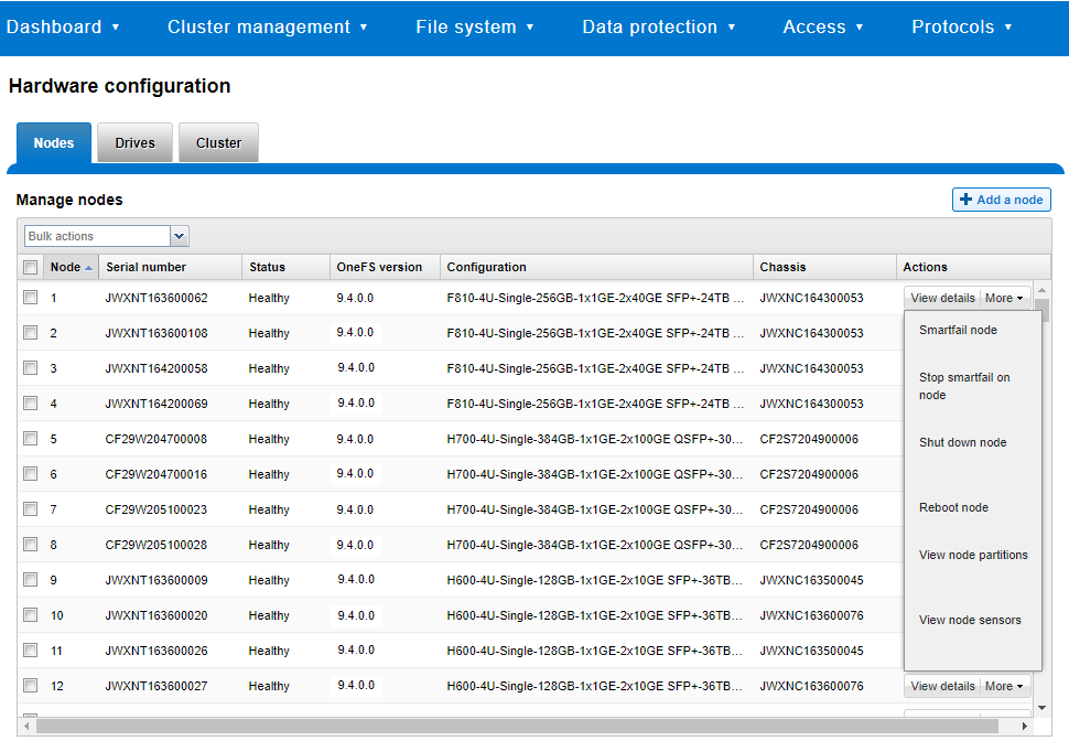
Similarly, the following CLI commands first initiate and then halt the node smartfail process, respectively. First, the ‘isi devices node smartfail’ command kicks off the smartfail process on a node and removes it from the cluster.
# isi devices node smartfail -h Syntax # isi devices node smartfail [--node-lnn <integer>] [--force | -f] [--verbose | -v]
If necessary, the ‘isi devices node stopfail’ command can be used to discontinue the smartfail process on a node.
# isi devices node stopfail -h Syntax isi devices node stopfail [--node-lnn <integer>] [--force | -f] [--verbose | -v]
Similarly, individual drives within a node can be smartfailed with the ‘isi devices drive smartfail’ CLI command.
# isi devices drive smartfail { <bay> | --lnum <integer> | --sled <string> }
[--node-lnn <integer>]
[{--force | -f}]
[{--verbose | -v}]
[{--help | -h}]Author: Nick Trimbee

OneFS SmartPools and the FilePolicy Job
Fri, 24 Jun 2022 18:22:15 -0000
|Read Time: 0 minutes
Traditionally, OneFS has used the SmartPools jobs to apply its file pool policies. To accomplish this, the SmartPools job visits every file, and the SmartPoolsTree job visits a tree of files. However, the scanning portion of these jobs can result in significant random impact to the cluster and lengthy execution times, particularly in the case of the SmartPools job. To address this, OneFS also provides the FilePolicy job, which offers a faster, lower impact method for applying file pool policies than the full-blown SmartPools job.
But first, a quick Job Engine refresher…
As we know, the Job Engine is OneFS’ parallel task scheduling framework, and is responsible for the distribution, execution, and impact management of critical jobs and operations across the entire cluster.
The OneFS Job Engine schedules and manages all data protection and background cluster tasks: creating jobs for each task, prioritizing them, and ensuring that inter-node communication and cluster wide capacity utilization and performance are balanced and optimized. Job Engine ensures that core cluster functions have priority over less important work and gives applications integrated with OneFS – Isilon add-on software or applications integrating to OneFS by means of the OneFS API – the ability to control the priority of their various functions to ensure the best resource utilization.
Each job, such as the SmartPools job, has an “Impact Profile” comprising a configurable policy and a schedule that characterizes how much of the system’s resources the job will take – plus an Impact Policy and an Impact Schedule. The amount of work a job has to do is fixed, but the resources dedicated to that work can be tuned to minimize the impact to other cluster functions, like serving client data.
Here’s a list of the specific jobs that are directly associated with OneFS SmartPools:
Job | Description |
SmartPools | Job that runs and moves data between the tiers of nodes within the same cluster. Also executes the CloudPools functionality if licensed and configured. |
SmartPoolsTree | Enforces SmartPools file policies on a subtree. |
FilePolicy | Efficient changelist-based SmartPools file pool policy job. |
IndexUpdate | Creates and updates an efficient file system index for FilePolicy job. |
SetProtectPlus | Applies the default file policy. This job is disabled if SmartPools is activated on the cluster. |
In conjunction with the IndexUpdate job, FilePolicy improves job scan performance by using a ‘file system index’, or changelist, to find files needing policy changes, rather than a full tree scan.
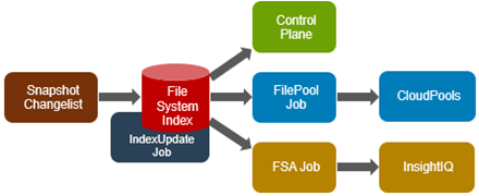
Avoiding a full treewalk dramatically decreases the amount of locking and metadata scanning work the job is required to perform, reducing impact on CPU and disk – albeit at the expense of not doing everything that SmartPools does. The FilePolicy job enforces just the SmartPools file pool policies, as opposed to the storage pool settings. For example, FilePolicy does not deal with changes to storage pools or storage pool settings, such as:
- Restriping activity due to adding, removing, or reorganizing node pools
- Changes to storage pool settings or defaults, including protection
However, most of the time, SmartPools and FilePolicy perform the same work. Disabled by default, FilePolicy supports the full range of file pool policy features, reports the same information, and provides the same configuration options as the SmartPools job. Because FilePolicy is a changelist-based job, it performs best when run frequently – once or multiple times a day, depending on the configured file pool policies, data size, and rate of change.
Job schedules can easily be configured from the OneFS WebUI by navigating to Cluster Management > Job Operations, highlighting the desired job, and selecting ‘View\Edit’. The following example illustrates configuring the IndexUpdate job to run every six hours at a LOW impact level with a priority value of 5:
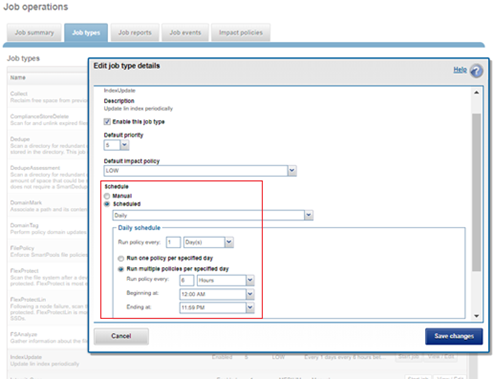
When enabling and using the FilePolicy and IndexUpdate jobs, the recommendation is to continue running the SmartPools job as well, but at a reduced frequency (monthly).
In addition to running on a configured schedule, the FilePolicy job can also be executed manually.
FilePolicy requires access to a current index. If the IndexUpdate job has not yet been run, attempting to start the FilePolicy job will fail with the error shown in the following figure. Instructions in the error message appear, prompting to run the IndexUpdate job first. When the index has been created, the FilePolicy job will run successfully. The IndexUpdate job can be run several times daily (that is, every six hours) to keep the index current and prevent the snapshots from getting large.
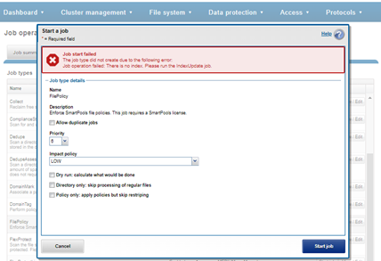
Consider using the FilePolicy job with the job schedules below for workflows and datasets with the following characteristics:
- Data with long retention times
- Large number of small files
- Path-based File Pool filters configured
- Where the FSAnalyze job is already running on the cluster (InsightIQ monitored clusters)
- There is already a SnapshotIQ schedule configured
- When the SmartPools job typically takes a day or more to run to completion at LOW impact
For clusters without the characteristics described above, the recommendation is to continue running the SmartPools job as usual and not to activate the FilePolicy job.
The following table provides a suggested job schedule when deploying FilePolicy:
Job | Schedule | Impact | Priority |
FilePolicy | Every day at 22:00 | LOW | 6 |
IndexUpdate | Every six hours, every day | LOW | 5 |
SmartPools | Monthly – Sunday at 23:00 | LOW | 6 |
Because no two clusters are the same, this suggested job schedule may require additional tuning to meet the needs of a specific environment.
Note that when clusters running older OneFS versions and the FSAnalyze job are upgraded to OneFS 8.2.x or later, the legacy FSAnalyze index and snapshots are removed and replaced by new snapshots the first time that IndexUpdate is run. The new index stores considerably more file and snapshot attributes than the old FSA index. Until the IndexUpdate job effects this change, FSA keeps running on the old index and snapshots.
Author: Nick Trimbee

Preparations for Upgrading a CloudPools Environment
Thu, 23 Jun 2022 15:51:46 -0000
|Read Time: 0 minutes
Introduction
CloudPools 2.0 brings many improvements and is released along with OneFS 8.2.0. It’s valuable to be able to upgrade OneFS from 8.x to 8.2.x or later and leverage the data management benefits of CloudPools 2.0.
This blog describes the preparations for upgrading a CloudPools environment. The purpose is to avoid potential issues when upgrading OneFS from 8.x to 8.2.x or later (that is, from CloudPools 1.0 to CloudPools 2.0).
For the recommended procedure for upgrading a CloudPools environment, see the document PowerScale CloudPools: Upgrading 8.x to 8.2.2.x or later.
For the best practices and considerations for CloudPools upgrades, see the white paper Dell PowerScale: CloudPools and ECS.
This blog covers the preparations both on cloud providers and on PowerScale clusters.
Cloud providers
CloudPools is a OneFS feature that allows customers to archive or tier data from a PowerScale cluster to cloud storage, including public cloud providers such as Amazon Web Services (AWS), Microsoft Azure, Google Cloud, Alibaba Cloud, or a private cloud based on Dell ECS.
Important: Run the isi cloud account list command to verify which cloud providers are used for CloudPools. Different authentications are used with different cloud providers for CloudPools, which might cause potential issues when upgrading a CloudPools environment.
AWS signature authentication is used for AWS, Dell ECS, and Google Cloud. In OneFS releases prior to 8.2, AWS SigV2 is only supported for CloudPools. Starting from OneFS 8.2, AWS SigV4 is added, which provides an extra level of security for authentication with the enhanced algorithm. For more information about V4, see Authenticating Requests: AWS Signature V4. AWS SigV4 will be used automatically for CloudPools in OneFS 8.2.x or later if the configurations (CloudPools and cloud providers) are correct. Please note that a different authentication is used for Azure or Alibaba Cloud.
If public cloud providers are used in a customer’s environment, there should be no issues because all configurations are already created by public cloud providers.
If Dell ECS is used in a customer’s environment, the ECS configurations are implemented separately and you need make sure that the configurations are correct on ECS, including load balancer and Domain Name System (DNS).
This section only covers the preparations for CloudPools and Dell ECS before upgrading OneFS from 8.x to 8.2.x or later.
Dell ECS
In general, CloudPools may already be archiving a lot of data from a PowerScale (Isilon) cluster to ECS before an upgrade OneFS from 8.x to 8.2.x or later. That means that most of the configurations should be created for CloudPools. For more information about CloudPools and ECS, see the white paper Dell PowerScale: CloudPools and ECS.
This section covers the following configurations for ECS before a OneFS upgrade from 8.x to 8.2.x or later.
- Load balancer
- DNS
- Base URL
Load balancer
A load balancer balances traffic to the various ECS nodes from the PowerScale cluster, and can provide much better performance and throughput for CloudPools. A load balancer is strongly recommended for CloudPools 2.0 and ECS. The following white papers provide information about how to implement a load balancer with ECS:
DNS
AWS always has a wildcard DNS record configured. See the document Virtual hosting of buckets, which introduces path-style access and virtual hosted-style access for a bucket. It also shows how to associate a hostname with an Amazon S3 bucket using CNAMEs for virtual hosted-style access.
Meanwhile, the path-style URL will be deprecated on September 23, 2022. Buckets created after that date must be referenced using the virtual-hosted model. For the reasons behind moving to the virtual-hosted model, see the document Amazon S3 Path Deprecation Plan – The Rest of the Story.
ECS supports Amazon S3 compatible applications that use virtual host-style and path-style addressing schemes. (For more information, see document Bucket and namespace addressing.) And, to help ensure the proper DNS configuration for ECS, see the document DNS configuration.
The procedure for configuring DNS depends on your DNS server or DNS provider.
For example, a DNS is set up on a Windows server. The following two tables and three figures show the DNS entries created. The customer must create their own DNS entries.
Name | Record Type | FQDN | IP Address | Comment |
ecs | A | ecs.demo.local | 192.168.1.40 | The FQDN of the load balancer will be ecs.demo.local. |
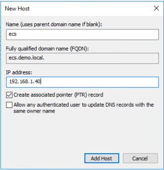
Name | Record Type | FQDN | FQDN for | Comment |
cloudpools_uri | CNAME | cloudpools_uri.demo.local | ecs.demo.local | If you create an SSL certificate for the ECS S3 service, it must have the certificate and the non-wildcard version as a Subject Alternate Name. |
*.cloudpools_uri | CNAME | *.cloudpools_uri.demo.local | ecs.demo.local | Used for virtual host addressing for a bucket. |
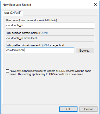
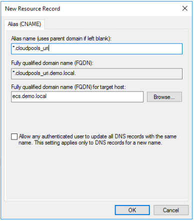
Base URL
In CloudPools 2.0 and ECS, a base URL must be created on ECS. For details about creating a Base URL on ECS, see the section Appendix A Base URL in the white paper Dell PowerScale: CloudPools and ECS.
When creating a new Base URL, keep the default setting (No) for Use with Namespace. Make sure that the Base URL is the FQDN alias of the load balancer virtual IP.
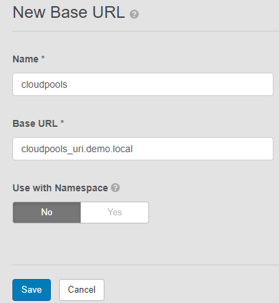
PowerScale clusters
If SyncIQ is configured for CloudPools, run the following commands on the source and target PowerScale cluster to check and record the CloudPools configurations, including CloudPools storage accounts, CloudPool, file pool policies, and SyncIQ policies.
# isi cloud accounts list -v # isi cloud pools list -v # isi filepool policies list -v # isi sync policies list -v
For CloudPools and ECS, please be sure that URI is the FQDN alias of the load balancer virtual IP.
Important: It is strongly recommended that no job (such as for CloudPools/SmartPools, SyncIQ, and NDMP) be running before upgrading.
In a SyncIQ environment, upgrade the SyncIQ target cluster before upgrading the source cluster. OneFS allows SyncIQ to send CP1.0 formatted SmartLink files to the target, where they will be converted into CP2.0 formatted SmartLink files. (If the source cluster is upgraded first, Sync operations will fail until both are upgraded; the only known resolution is to reconfigure the Sync policy to "Deep Copy".)
And the customer may have active (read & write) CloudPools accounts both on source and target PowerScale clusters, replicating SmartLink files of active CloudPools accounts bidirectionally. That means that the source is also a target. In this case, you need to reconfigure the Sync policy to “Deep Copy” on one of PowerScale clusters. After that, the target with replicated SmartLink files should be upgraded first.
Summary
This blog covered what you need to check, on cloud providers and PowerScale clusters, before upgrading OneFS from 8.x to 8.2.x or later (that is, from CloudPools 1.0 to CloudPools 2.0). My hope is that it can help you avoid potential CloudPools issues when upgrading a CloudPools environment.
Author: Jason He, Principal Engineering Technologist

PowerScale Now Supports Secure Boot Across More Platforms
Tue, 21 Jun 2022 19:55:15 -0000
|Read Time: 0 minutes
Dell PowerScale OneFS 9.3.0.0 first introduced support for Secure Boot on the Dell Isilon A2000 platform. Now, OneFS 9.4.0.0 expands that support across the PowerScale A300, A3000, B100, F200, F600, F900, H700, H7000, and P100 platforms.
Secure Boot was introduced as part of the Unified Extensible Firmware Interface (UEFI) Forums of the UEFI 2.3.1 specification. The goal for Secure Boot is to ensure device security in the preboot environment by allowing only authorized EFI binaries to be loaded during the process.
The operating system boot loaders are signed with a digital signature. PowerScale Secure Boot takes the UEFI framework further by including the OneFS kernel and modules. The UEFI infrastructure is responsible for the EFI signature validation and binary loading within UEFI Secure Boot. Also, the FreeBSD veriexec function can perform signature validation for the boot loader and kernel. The PowerScale Secure Boot feature runs during the nodes’ bootup process only, using public-key cryptography to verify the signed code and ensure that only trusted code is loaded on the node.
Supported platforms
PowerScale Secure Boot is available on the following platform:
Platform | NFP version | OneFS release |
Isilon A2000 | 11.4 or later | 9.3.0.0 or later |
PowerScale A300, A3000, B100, F200, F600, F900, H700, H7000, P100 | 11.4 or later | 9.3.0.0 or later |
Considerations
Before configuring the PowerScale Secure Boot feature, consider the following:
- Isilon and PowerScale nodes are not shipped with PowerScale Secure Boot enabled. However, you can enable the feature to meet site requirements.
- A PowerScale cluster composed of PowerScale Secure Boot enabled nodes, and PowerScale Secure Boot disabled nodes, is supported.
- A license is not required for PowerScale Secure Boot because the feature is natively supported.
- At any point, you can enable or disable the PowerScale Secure Boot feature.
- Plan a maintenance window to enable or disable the PowerScale Secure Boot feature, because a node reboot is required during the process to toggle the feature.
- The PowerScale Secure Boot feature does not impact cluster performance, because the feature is only run at bootup.
Configuration
For more information about configuring the PowerScale Secure Boot feature, see the document Dell PowerScale OneFS Secure Boot.
Author: Aqib Kazi

OneFS SnapRevert Job
Tue, 21 Jun 2022 19:44:06 -0000
|Read Time: 0 minutes
There have been a couple of recent inquiries from the field about the SnapRevert job.
For context, SnapRevert is one of three main methods for restoring data from a OneFS snapshot. The options are shown here:
| Method | Description |
| Copy | Copying specific files and directories directly from the snapshot |
| Clone | Cloning a file from the snapshot |
| Revert | Reverting the entire snapshot using the SnapRevert job |
However, the most efficient of these approaches is the SnapRevert job, which automates the restoration of an entire snapshot to its top-level directory. This allows for quickly reverting to a previous, known-good recovery point (for example, if there is a virus outbreak). The SnapRevert job can be run from the Job Engine WebUI, and requires adding the desired snapshot ID.
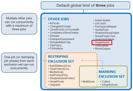
There are two main components to SnapRevert:
- The file system domain that the objects are put into.
- The job that reverts everything back to what’s in a snapshot.
So, what exactly is a SnapRevert domain? At a high level, a domain defines a set of behaviors for a collection of files under a specified directory tree. The SnapRevert domain is described as a restricted writer domain, in OneFS parlance. Essentially, this is a piece of extra filesystem metadata and associated locking that prevents a domain’s files from being written to while restoring a last known good snapshot.
Because the SnapRevert domain is essentially just a metadata attribute placed onto a file/directory, a best practice is to create the domain before there is data. This avoids having to wait for DomainMark (the aptly named job that marks a domain’s files) to walk the entire tree, setting that attribute on every file and directory within it.
The SnapRevert job itself actually uses a local SyncIQ policy to copy data out of the snapshot, discarding any changes to the original directory. When the SnapRevert job completes, the original data is left in the directory tree. In other words, after the job completes, the file system (HEAD) is exactly as it was at the point in time that the snapshot was taken. The LINs for the files or directories do not change because what is there is not a copy.
To manually run SnapRevert, go to the OneFS WebUI > Cluster Management > Job Operations > Job Types > SnapRevert, and click the Start Job button.
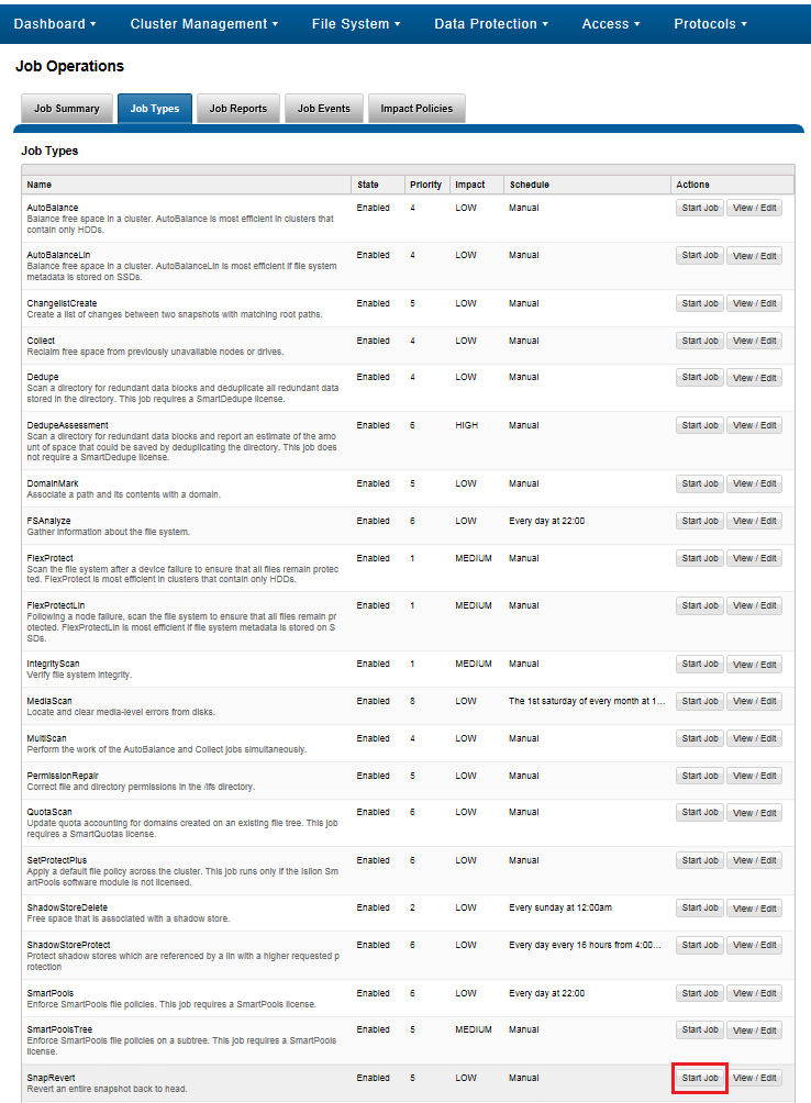
Also, you can adjust the job’s impact policy and relative priority, if desired.
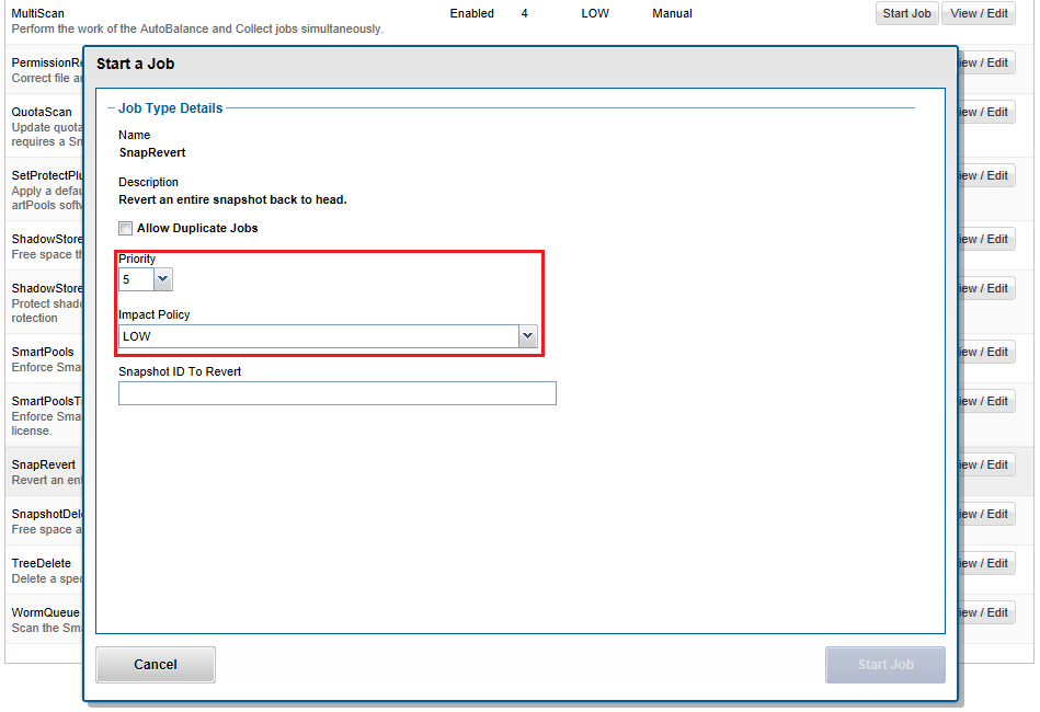
Before a snapshot is reverted, SnapshotIQ creates a point-in-time copy of the data that is being replaced. This enables the snapshot revert to be undone later, if necessary.
Also, individual files, rather than entire snapshots, can also be restored in place using the isi_file_revert command-line utility.
# isi_file_revert usage: isi_file_revert -l lin -s snapid isi_file_revert -p path -s snapid -d (debug output) -f (force, no confirmation)
This can help drastically simplify virtual machine management and recovery, for example.
Before creating snapshots, it is worth considering that reverting a snapshot requires that a SnapRevert domain exist for the directory that is being restored. As such, we recommend that you create SnapRevert domains for those directories while the directories are empty. Creating a domain for an empty (or sparsely populated) directory takes considerably less time.
Files may belong to multiple domains. Each file stores a set of domain IDs indicating which domain they belong to in their inode’s extended attributes table. Files inherit this set of domain IDs from their parent directories when they are created or moved. The domain IDs refer to domain settings themselves, which are stored in a separate system B-tree. These B-tree entries describe the type of the domain (flags), and various other attributes.
As mentioned, a Restricted-Write domain prevents writes to any files except by threads that are granted permission to do so. A SnapRevert domain that does not currently enforce Restricted-Write shows up as (Writable) in the CLI domain listing.
Occasionally, a domain will be marked as (Incomplete). This means that the domain will not enforce its specified behavior. Domains created by the job engine are incomplete if not all files that are part of the domain are marked as being members of that domain. Since each file contains a list of domains of which it is a member, that list must be kept up to date for each file. The domain is incomplete until each file’s domain list is correct.
Besides SnapRevert, OneFS also uses domains for SyncIQ replication and SnapLock immutable archiving.
A SnapRevert domain must be created on a directory before it can be reverted to a particular point in time snapshot. As mentioned before, we recommend creating SnapRevert domains for a directory while the directory is empty.
The root path of the SnapRevert domain must be the same root path of the snapshot. For instance, a domain with a root path of /ifs/data/marketing cannot be used to revert a snapshot with a root path of /ifs/data/marketing/archive.
For example, for snapshot DailyBackup_04-27-2021_12:00 which is rooted at /ifs/data/marketing/archive, you would perform the following:
1. Set the SnapRevert domain by running the DomainMark job (which marks all files).
# isi job jobs start domainmark --root /ifs/data/marketing --dm-type SnapRevert
2. Verify that the domain has been created.
# isi_classic domain list –l
To restore a directory back to the state it was in at the point in time when a snapshot was taken, you need to:
- Create a SnapRevert domain for the directory
- Create a snapshot of a directory
To accomplish this, do the following:
1. Identify the ID of the snapshot you want to revert by running the isi snapshot snapshots view command and picking your point in time (PIT).
For example:
# isi snapshot snapshots view DailyBackup_04-27-2021_12:00 ID: 38 Name: DailyBackup_04-27-2021_12:00 Path: /ifs/data/marketing Has Locks: No Schedule: daily Alias: - Created: 2021-04-27T12:00:05 Expires: 2021-08-26T12:00:00 Size: 0b Shadow Bytes: 0b % Reserve: 0.00% % Filesystem: 0.00% State: active
2. Revert to a snapshot by running the isi job jobs start command. The following command reverts to snapshot ID 38 named DailyBackup_04-27-2021_12:00.
# isi job jobs start snaprevert --snapid 38
You can also perform this action from the WebUI. Go to Cluster Management > Job Operations > Job Types > SnapRevert, and click the Start Job button.
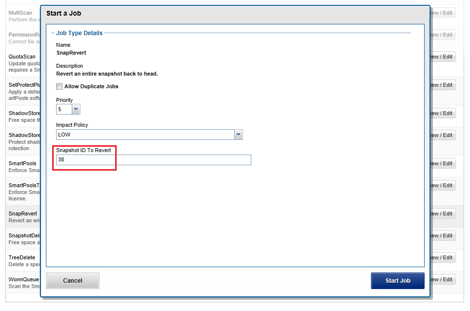
OneFS automatically creates a snapshot before the SnapRevert process reverts the specified directory tree. The naming convention for these snapshots is of the form: <snapshot_name>.pre_revert.*
# isi snap snap list | grep pre_revert 39 DailyBackup_04-27-2021_12:00.pre_revert.1655328160 /ifs/data/marketing
This allows for an easy rollback of a SnapRevert if the desired results are not achieved.
If a domain is currently preventing the modification or deletion of a file, a protection domain cannot be created on a directory that contains that file. For example, if files under /ifs/data/smartlock are set to a WORM state by a SmartLock domain, OneFS will not allow a SnapRevert domain to be created on /ifs/data/.
If desired or required, SnapRevert domains can also be deleted using the job engine CLI. For example, to delete the SnapRevert domain at /ifs/data/marketing:
# isi job jobs start domainmark --root /ifs/data/marketing --dm-type SnapRevert --delete
Author: Nick Trimbee

Data Access in OneFS - Part 1: Introduction to OneFS File Permissions
Thu, 16 Jun 2022 20:29:24 -0000
|Read Time: 0 minutes
About this blog series
Have you ever been confused about PowerScale OneFS file system multi-protocol data access? If so, this blog series will help you out. We’ll try to demystify OneFS multi-protocol data access. Different Network Attached Storage vendors have different designs for implementing multi-protocol data access. In OneFS multi-protocol data access, you can access the same set of data consistently with different operating systems and protocols.
To make it simple, the overall data access process in OneFS includes:
- When a client user tries to access OneFS cluster data by means of protocols (such as SMB, NFS, and S3), OneFS must first authenticate the client user.
- When the authentication succeeds, OneFS checks whether the user has permission on file share, where the access level depends on your access protocol, such as SMB share, NFS export, or S3 bucket.
- Only when the user is authorized to have permission on the file shares will OneFS apply user mapping rules and generate an access token for the user in most cases. The access token contains the following information:
- The user's Security Identifier (SID), User Identifier (UID), and Group Identifier (GID).
- The user's supplemental groups
- The user's role-based access control (RBAC) privileges
Finally, OneFS enforces the permissions on the target data for the user. This process evaluates the file permissions based on the user's access token and file share level permissions.
Does it sound simple but some details still confusing? Like, what exactly are UIDs, GIDs, and SIDs? What’s an access token? How does OneFS evaluate the file permissions? and so on. Don’t worry if you are not familiar with these concepts. Keep reading and we’ll explain!
To make it easier, we will start with OneFS file permissions, and then introduce OneFS access tokens. Finally, we will see how data access depends on the protocol you use.
In this blog series, we’ll cover the following topics:
- Data Access in OneFS - Part 1: Introduction to OneFS File Permissions
- Data Access in OneFS - Part 2: Introduction to OneFS Access Tokens
- Data Access in OneFS - Part 3: Why Use Different Protocols?
- Data Access in OneFS - Part 4: Using NFSv3 and NFSv4.x
- Data Access in OneFS - Part 5: Using SMB
- Data Access in OneFS - Part 6: Using S3
- More to add…
Now let's have a look at OneFS file permissions. In a multi-protocol environment, the OneFS operating system is designed to support basic POSIX mode bits and Access Control Lists (ACLs). Therefore, two file permission states are designated:
- POSIX mode bits - authoritative with a synthetic ACL
- OneFS ACL - authoritative with approximate POSIX mode bits
POSIX mode bits - authoritative with a synthetic ACL
POSIX mode bits only define three specific permissions: read(r), write(w), and execute(x). Meanwhile, there are three classes to which you can assign permissions: Owner, Group, and Others.
- Owner: represents the owner of a file/directory.
- Group: represents the group of a file/directory.
- Others: represents the users who are not the owner, nor a member of the group.
The ls -le command displays a file’s permissions; the ls -led command displays a directory’s permissions. If it has these permissions:
-rw-rw-r--
then:
-rw-rw-r-- means that the owner has read and write permissions
-rw-rw-r-- means that the group has read and write permissions
-rw-rw-r-- means that all others have only read permissions
In the following example for the file posix-file.txt, the file owner Joe has read and write access permissions, the file group Market has read and write access permissions, and all others only have read access permissions.
Also displayed here is the synthetic ACL (shown beneath the SYNTHETIC ACL flag) which indicates that the file is in the POSIX mode bit file permission state. There are three Access Control Entities (ACEs) created for the synthetic ACL, all of which is another way of representing the file’s POSIX mode bits permissions.
vonefs-aima-1# ls -le posix-file.txt -rw-rw-r-- 1 Joe Market 65 May 28 02:08 posix-file.txt OWNER: user:Joe GROUP: group:Market SYNTHETIC ACL 0: user:Joe allow file_gen_read,file_gen_write,std_write_dac 1: group:Market allow file_gen_read,file_gen_write 2: everyone allow file_gen_read
When OneFS receives a user access request, it generates an access token for the user and compares the token to the file permissions – in this case, the POSIX mode bits.
OneFS ACL authoritative with approximate POSIX mode bits
In contrast to POSIX mode bits, OneFS ACLs support more expressive permissions. (For all available permissions, which are listed in Table 1 through Table 3 of the documentation, see Access Control Lists on Dell EMC PowerScale OneFS.) A OneFS ACL consists of one or more Access Control Entries (ACEs). A OneFS ACE contains the following information:
- ACE index: indicates the ACE order in an ACL
- Identity type: indicates the identity type, supported identity type including user, group, everyone, creator_owner, creator_group, or owner_rights
- Identity ID: in OneFS, the UID/GID/SID is stored on disk instead of user names or group names. The name of a user or group is for display only.
- ACE type: The type of the ACE (allow or deny)
- ACE permissions and inheritance flags: A list of permissions and inheritance flags separated by commas
For example, the ACE "0: group:Engineer allow file_gen_read,file_gen_execute" indicates that its index is 0, and allows the group called Engineer to have file_gen_read and file_gen_execute access permissions.
The following example shows a full ACL for a file. Although there is no SYNTHETIC ACL flag, there is a "+" character following the POSIX mode bits that indicates that the file is in the OneFS real ACL state. The file’s OneFS ACL grants full permission to users Joe and Bob. It also grants file_gen_read and file_gen_execute permissions to the group Market and to everyone. In this case, the POSIX mode bits are for representation only: you cannot tell the accurate file permissions from the approximate POSIX mode bits. You should therefore always rely on the OneFS ACL to check file permissions.
vonefs-aima-1# ls -le acl-file.txt -rwxrwxr-x + 1 Joe Market 69 May 28 01:08 acl-file.txt OWNER: user:Joe GROUP: group:Market 0: user:Joe allow file_gen_all 1: group:Market allow file_gen_read,file_gen_execute 2: user:Bob allow file_gen_all 3: everyone allow file_gen_read,file_gen_execute
No matter the OneFS file permission state, the on-disk identity for a file is always a UID, a GID, or an SID. So, for the above two files, file permissions stored on disk are:
vonefs-aima-1# ls -len posix-file.txt -rw-rw-r-- 1 2001 2003 65 May 28 02:08 posix-file.txt OWNER: user:2001 GROUP: group:2003 SYNTHETIC ACL 0: user:2001 allow file_gen_read,file_gen_write,std_write_dac 1: group:2003 allow file_gen_read,file_gen_write 2: SID:S-1-1-0 allow file_gen_read vonefs-aima-1# ls -len acl-file.txt -rwxrwxr-x + 1 2001 2003 69 May 28 01:08 acl-file.txt OWNER: user:2001 GROUP: group:2003 0: user:2001 allow file_gen_all 1: group:2003 allow file_gen_read,file_gen_execute 2: user:2002 allow file_gen_all 3: SID:S-1-1-0 allow file_gen_read,file_gen_execute
When OneFS receives a user access request, it generates an access token for the user and compares the token to the file permissions. OneFS grants access when the file permissions include an ACE that allows the identity in the token to access the file, and does not include an ACE that denies the identity access.
When evaluating the file permission for a user's access token, OneFS checks the ACEs one by one by following the ACEs index order and stops checking when the following conditions are met:
- All of the required permissions for the user access request are allowed by ACLs, and the access request is authorized.
- Any one of the required permissions for the user access request is explicitly denied by ACLs, and the access request is denied.
- All ACEs have been checked, but not all required permissions for the user access request are allowed by ACLs, then the access request is also denied.
Let’s say we have a file named acl-file01.txt that has the file permissions shown below. When user Bob tries to read the data of the file, OneFS checks the ACEs from index 0 to index 3. When checking ACE index 1, it explicitly denies Bob read data permissions. The ACLs then stop checking, and read access is denied.
vonefs-aima-1# ls -le acl-file01.txt -rwxrw-r-- + 1 Joe Market 12 May 28 06:19 acl-file01.txt OWNER: user:Joe GROUP: group:Market 0: user:Joe allow file_gen_all 1: user:Bob deny file_gen_read 2: user:Bob allow file_gen_read,file_gen_write 3: everyone allow file_gen_read
Now let’s say that we still have the file named acl-file01.txt, but the file permissions are now a little different, as shown below. When user Bob tries to read the data of the file, OneFS checks the ACEs from index 0 to index 3. When checking ACE index 1, it explicitly allows Bob to have read permissions. The ACLs checking process therefore ends, and read access is authorized. Therefore, it is recommended to put all “deny” ACEs in front of “allow” ACEs if you want to explicitly deny specific permissions for specific users/groups.
vonefs-aima-1# ls -le acl-file01.txt -rwxrw-r-- + 1 Joe Market 12 May 28 06:19 acl-file01.txt OWNER: user:Joe GROUP: group:Market 0: user:Joe allow file_gen_all 1: user:Bob allow file_gen_read,file_gen_write 2: user:Bob deny file_gen_read 3: everyone allow file_gen_read
File permission state changes
As mentioned before, a file can only be in one state at a time. However, the file permission state of the file may be flipped. If a file is in POSIX, it can be flipped to an ACL file by modifying the permissions using SMB/NFSv4 clients or by using the chmod command in OneFS. If a file is in ACL, it can be flipped to a POSIX file, by using the OneFS CLI command: chmod –b XXX <filename>. The ‘XXX’ specifies the new POSIX permission. For more examples, see File permission state changes.
Now, you should be able to check a file’s permission on OneFS with the command ls -len filename, and check a directory’s permissions on OneFS with the command ls -lend directory_name.
In my next blog, we will cover what an access token is and how to check a user’s access token!
Resources
Author: Lieven Lin

Understanding ‘Total inlined data savings’ When Using ’isi_cstats’
Thu, 12 May 2022 14:22:45 -0000
|Read Time: 0 minutes
Recently a customer contacted us to tell us that he thought that there was an error in the output of the OneFS CLI command ‘isi_cstats’. Starting with OneFS 9.3, the ‘isi_cstats’ command includes the accounted number of inlined files within /ifs. It also contains a statistic called “Total inlined data savings”.
This customer expected that the ‘Total inlined data savings’ number was simply ‘Total inlined files’ multiplied by 8KB. The reason he thought this number was wrong was that this number does not consider the protection level.
In OneFS, for the 2d:1n protection level, each file smaller than 128KB is stored as 3X mirrors. Take the screenshot below as an example.
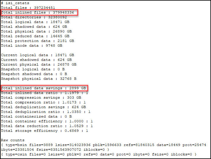
If we do some calculation here,
379,948,336 * 8KB = 3,039,586,688KiB = 2898.78GiB
we can see that the 2,899GiB from the command output is calculated as one block per inlined file. So, in our example, the customer would think that ‘Total inlined data savings’ should report 2898.78 GiB * 3, because of the 2d:1n protection level.
Well, this statistic is not the actual savings, it is really the logical on-disk cost for all inlined files. We can't accurately report the physical savings because it depends on the non-inlined protection overhead, which can vary. For example:
- If the protection level is 2d:1n, without the data inlining in 8KB inode feature, each of the inlined files would cost 8KB * 3.
- If the protection level is 3d:1n1d, it will become 8KB * 4.
One more thing to consider, if a file is smaller than 8KB after compression, it will be inlined into an inode as well. Therefore, this statistic doesn't represent logical savings either, because it doesn't take compression into account. To report the logical savings, total logical size for all inlined files should be tracked.
To avoid any confusion, we plan to rename this statistic to “Total inline data” in the next version of OneFS. We also plan to show more useful information about total logical data of inlined files, in addition to “Total inline data”.
For more information about the reporting of data reduction features, see the white paper PowerScale OneFS: Data Reduction and Storage Efficiency on the Info Hub.
Author: Yunlong Zhang, Principal Engineering Technologist

OneFS Data Reduction and Efficiency Reporting
Wed, 04 May 2022 14:36:26 -0000
|Read Time: 0 minutes
Among the objectives of OneFS reduction and efficiency reporting is to provide ‘industry standard’ statistics, allowing easier comprehension of cluster efficiency. It’s an ongoing process, and prior to OneFS 9.2 there was limited tracking of certain filesystem statistics – particularly application physical and filesystem logical – which meant that data reduction and storage efficiency ratios had to be estimated. This is no longer the case, and OneFS 9.2 and later provides accurate data reduction and efficiency metrics at a per-file, quota, and cluster-wide granularity.
The following table provides descriptions for the various OneFS reporting metrics, while also attempting to rationalize their naming conventions with other general industry terminology:
OneFS Metric | Also Known As | Description |
Protected logical | Application logical | Data size including sparse data, zero block eliminated data, and CloudPools data stubbed to a cloud tier. |
Logical data | Effective
Filesystem logical | Data size excluding protection overhead and sparse data, and including data efficiency savings (compression and deduplication). |
Zero-removal saved |
| Capacity savings from zero removal. |
Dedupe saved |
| Capacity savings from deduplication. |
Compression saved |
| Capacity savings from in-line compression. |
Preprotected physical | Usable
Application physical | Data size excluding protection overhead and including storage efficiency savings. |
Protection overhead |
| Size of erasure coding used to protect data. |
Protected physical | Raw
Filesystem physical | Total footprint of data including protection overhead FEC erasure coding) and excluding data efficiency savings (compression and deduplication). |
Dedupe ratio |
| Deduplication ratio. Will be displayed as 1.0:1 if there are no deduplicated blocks on the cluster. |
Compression ratio |
| Usable reduction ratio from compression, calculated by dividing ‘logical data’ by ‘preprotected physical’ and expressed as x:1. |
Inlined data ratio |
| Efficiency ratio from storing small files’ data within their inodes, thereby not requiring any data or protection blocks for their storage. |
Data reduction ratio | Effective to Usable | Usable efficiency ratio from compression and deduplication. Will display the same value as the compression ratio if there is no deduplication on the cluster. |
Efficiency ratio | Effective to Raw | Overall raw efficiency ratio expressed as x:1 |
So let’s take these metrics and look at what they represent and how they’re calculated.
- Application logical, or protected logical, is the application data that can be written to the cluster, irrespective of where it’s stored.
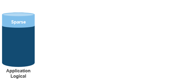
- Removing the sparse data from application logical results in filesystem logical, also known simply as logical data or effective. This can be data that was always sparse, was zero block eliminated, or data that has been tiered off-cluster by means of CloudPools, and so on.
(Note that filesystem logical was not accurately tracked in releases prior to OneFS 9.2, so metrics prior to this were somewhat estimated.)
- Next, data reduction techniques such as compression and deduplication further reduce filesystem logical to application physical, or pre-protected physical. This is the physical size of the application data residing on the filesystem drives, and does not include metadata, protection overhead, or data moved to the cloud.
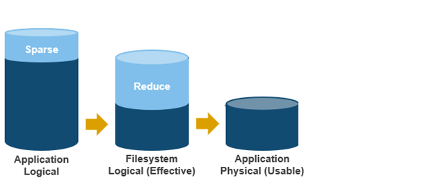
- Filesystem physical is application physical with data protection overhead added – including inode, mirroring, and FEC blocks. Filesystem physical is also referred to as protected physical.
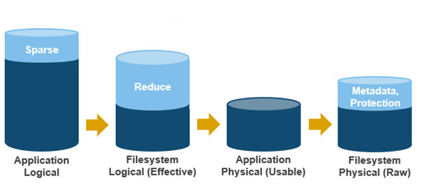
- The data reduction ratio is the amount that’s been reduced from the filesystem logical down to the application physical.
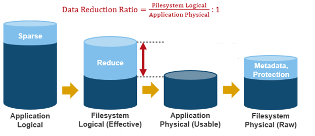
- Finally, the storage efficiency ratio is the filesystem logical divided by the filesystem physical.
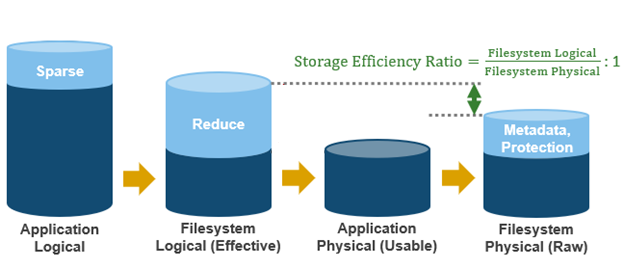
With the enhanced data reduction reporting in OneFS 9.2 and later, the actual statistics themselves are largely the same, just calculated more accurately.
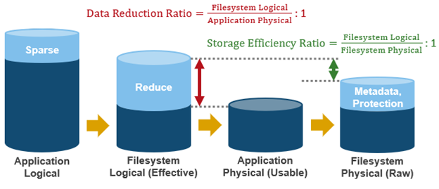
The storage efficiency data was available in releases prior to OneFS 9.2, albeit somewhat estimated, but the data reduction metrics were introduced with OneFS 9.2.
The following tools are available to query these reduction and efficiency metrics at file, quota, and cluster-wide granularity:
Realm | OneFS Command | OneFS Platform API |
File | isi get -D | |
Quota | isi quota list -v | 12/quota/quotas |
Cluster-wide | isi statistics data-reduction | 1/statistics/current?key=cluster.data.reduce.* |
Detailed Cluster-wide | isi_cstats | 1/statistics/current?key=cluster.cstats.* |
Note that the ‘isi_cstats’ CLI command provides some additional, behind-the-scenes details. The interface goes through platform API to fetch these stats.
The ‘isi statistics data-reduction’ CLI command is the most comprehensive of the data reduction reporting CLI utilities. For example:
# isi statistics data-reduction Recent Writes Cluster Data Reduction (5 mins) --------------------- ------------- ---------------------- Logical data 6.18M 6.02T Zero-removal saved 0 - Deduplication saved 56.00k 3.65T Compression saved 4.16M 1.96G Preprotected physical 1.96M 2.37T Protection overhead 5.86M 910.76G Protected physical 7.82M 3.40T Zero removal ratio 1.00 : 1 - Deduplication ratio 1.01 : 1 2.54 : 1 Compression ratio 3.12 : 1 1.02 : 1 Data reduction ratio 3.15 : 1 2.54 : 1 Inlined data ratio 1.04 : 1 1.00 : 1 Efficiency ratio 0.79 : 1 1.77 : 1
The ‘recent writes’ data in the first column provides precise statistics for the five-minute period prior to running the command. By contrast, the ‘cluster data reduction’ metrics in the second column are slightly less real-time but reflect the overall data and efficiencies across the cluster. Be aware that, in OneFS 9.1 and earlier, the right-hand column metrics are designated by the ‘Est’ prefix, denoting an estimated value. However, in OneFS 9.2 and later, the ‘logical data’ and ‘preprotected physical’ metrics are tracked and reported accurately, rather than estimated.
The ratio data in each column is calculated from the values above it. For instance, to calculate the data reduction ratio, the ‘logical data’ (effective) is divided by the ‘preprotected physical’ (usable) value. From the output above, this would be:
6.02 / 2.37 = 1.76 Or a Data Reduction ratio of 2.54:1
Similarly, the ‘efficiency ratio’ is calculated by dividing the ‘logical data’ (effective) by the ‘protected physical’ (raw) value. From the output above, this yields:
6.02 / 3.40 = 0.97 Or an Efficiency ratio of 1.77:1
OneFS SmartQuotas reports the capacity saving from in-line data reduction as a storage efficiency ratio. SmartQuotas reports efficiency as a ratio across the desired data set as specified in the quota path field. The efficiency ratio is for the full quota directory and its contents, including any overhead, and reflects the net efficiency of compression and deduplication. On a cluster with licensed and configured SmartQuotas, this efficiency ratio can be easily viewed from the WebUI by navigating to File System > SmartQuotas > Quotas and Usage. In OneFS 9.2 and later, in addition to the storage efficiency ratio, the data reduction ratio is also displayed.
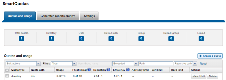
Similarly, the same data can be accessed from the OneFS command line by using the ‘isi quota quotas list’ CLI command. For example:
# isi quota quotas list Type AppliesTo Path Snap Hard Soft Adv Used Reduction Efficiency ---------------------------------------------------------------------------- directory DEFAULT /ifs No - - - 6.02T 2.54 : 1 1.77 : 1 ----------------------------------------------------------------------------
Total: 1
More detail, including both the physical (raw) and logical (effective) data capacities, is also available by using the ‘isi quota quotas view <path> <type>’ CLI command. For example:
# isi quota quotas view /ifs directory Path: /ifs Type: directory Snapshots: No Enforced: No Container: No Linked: No Usage Files: 5759676 Physical(With Overhead): 6.93T FSPhysical(Deduplicated): 3.41T FSLogical(W/O Overhead): 6.02T AppLogical(ApparentSize): 6.01T ShadowLogical: - PhysicalData: 2.01T Protection: 781.34G Reduction(Logical/Data): 2.54 : 1 Efficiency(Logical/Physical): 1.77 : 1
To configure SmartQuotas for in-line data efficiency reporting, create a directory quota at the top-level file system directory of interest, for example /ifs. Creating and configuring a directory quota is a simple procedure and can be performed from the WebUI by navigating to File System > SmartQuotas > Quotas and Usage and selecting Create a Quota. In the Create a quota dialog, set the Quota type to ‘Directory quota’, add the preferred top-level path to report on, select ’Application logical size’ for Quota Accounting, and set the Quota Limits to ‘Track storage without specifying a storage limit’. Finally, click the ‘Create Quota’ button to confirm the configuration and activate the new directory quota.
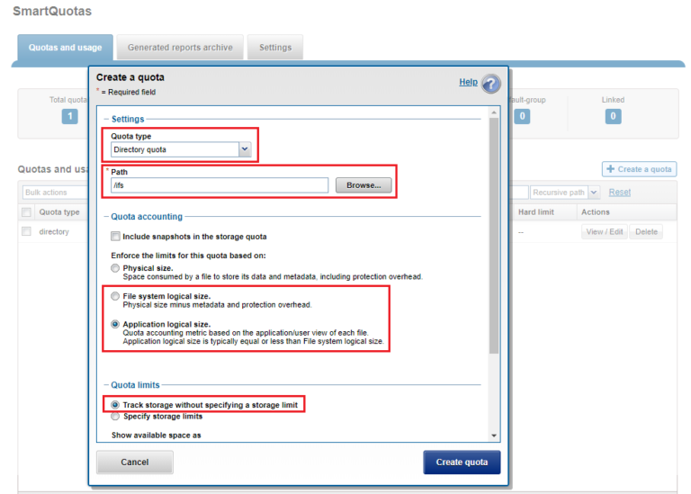
The efficiency ratio is a single, current-in time efficiency metric that is calculated per quota directory and includes the sum of in-line compression, zero block removal, in-line dedupe, and SmartDedupe. This is in contrast to a history of stats over time, as reported in the ‘isi statistics data-reduction’ CLI command output, described above. As such, the efficiency ratio for the entire quota directory will reflect what is actually there.
Author: Nick Trimbee

OneFS In-line Dedupe
Thu, 12 May 2022 14:48:01 -0000
|Read Time: 0 minutes
Among the features and functionality delivered in the new OneFS 9.4 release is the promotion of in-line dedupe to enabled by default, further enhancing PowerScale’s dollar-per-TB economics, rack density and value.
Part of the OneFS data reduction suite, in-line dedupe initially debuted in OneFS 8.2.1. However, it was enabled manually, so many customers simply didn’t use it. But with this enhancement, new clusters running OneFS 9.4 now have in-line dedupe enabled by default.
Cluster configuration | In-line dedupe | In-line compression |
New cluster running OneFS 9.4 | Enabled | Enabled |
New cluster running OneFS 9.3 or earlier | Disabled | Enabled |
Cluster with in-line dedupe enabled that is upgraded to OneFS 9.4 | Enabled | Enabled |
Cluster with in-line dedupe disabled that is upgraded to OneFS 9.4 | Disabled | Enabled |
That said, any clusters that upgrade to 9.4 will not see any change to their current in-line dedupe config during upgrade. Also, there is also no change to the behavior for in-line compression, which remains enabled by default in all OneFS versions from 8.1.3 onwards.
But before we examine the-under-the-hood changes in OneFS 9.4, let’s have a quick dedupe refresher.
Currently, OneFS in-line data reduction, which encompasses compression, dedupe, and zero block removal, is supported on the F900, F600, and F200 all-flash nodes, plus the F810, H5600, H700/7000, and A300/3000 Gen6.x chassis.

Within the OneFS data reduction pipeline, zero block removal is performed first, followed by dedupe, and then compression. This order allows each phase to reduce the scope of work each subsequent phase.
Unlike SmartDedupe, which performs deduplication once data has been written to disk, or post-process, in-line dedupe acts in real time, deduplicating data as is ingested into the cluster. Storage efficiency is achieved by scanning the data for identical blocks as it is received and then eliminating the duplicates.
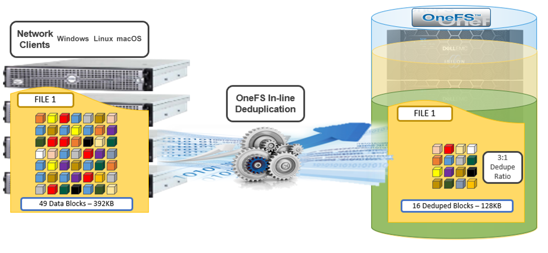
When in-line dedupe discovers a duplicate block, it moves a single copy of the block to a special set of files known as shadow stores. These are file-system containers that allow data to be stored in a sharable manner. As such, files stored under OneFS can contain both physical data and pointers, or references, to shared blocks in shadow stores.
Shadow stores are similar to regular files but are hidden from the file system namespace, so they cannot be accessed through a pathname. A shadow store typically grows to a maximum size of 2 GB, which is around 256 K blocks, and each block can be referenced by 32,000 files. If the reference count limit is reached, a new block is allocated, which may or may not be in the same shadow store. Also, shadow stores do not reference other shadow stores. And snapshots of shadow stores are not permitted because the data contained in shadow stores cannot be overwritten.
When a client writes a file to a node pool configured for in-line dedupe on a cluster, the write operation is divided up into whole 8 KB blocks. Each block is hashed, and its cryptographic ‘fingerprint’ is compared against an in-memory index for a match. At this point, one of the following will happen:
- If a match is discovered with an existing shadow store block, a byte-by-byte comparison is performed. If the comparison is successful, the data is removed from the current write operation and replaced with a shadow reference.
- When a match is found with another LIN, the data is written to a shadow store instead and is replaced with a shadow reference. Next, a work request is generated and queued that includes the location for the new shadow store block, the matching LIN and block, and the data hash. A byte-by-byte data comparison is performed to verify the match and the request is then processed.
- If no match is found, the data is written to the file natively and the hash for the block is added to the in-memory index.
For in-line dedupe to perform on a write operation, the following conditions need to be true:
- In-line dedupe must be globally enabled on the cluster.
- The current operation is writing data (not a truncate or write zero operation).
- The no_dedupe flag is not set on the file.
- The file is not a special file type, such as an alternate data stream (ADS) or an EC (endurant cache) file.
- Write data includes fully overwritten and aligned blocks.
- The write is not part of a rehydrate operation.
- The file has not been packed (containerized) by small file storage efficiency (SFSE).
OneFS in-line dedupe uses the 128-bit CityHash algorithm, which is both fast and cryptographically strong. This contrasts with the OneFS post-process SmartDedupe, which uses SHA-1 hashing.
Each node in a cluster with in-line dedupe enabled has its own in-memory hash index that it compares block fingerprints against. The index lives in system RAM and is allocated using physically contiguous pages and is accessed directly with physical addresses. This avoids the need to traverse virtual memory mappings and does not incur the cost of translation lookaside buffer (TLB) misses, minimizing dedupe performance impact.
The maximum size of the hash index is governed by a pair of sysctl settings, one of which caps the size at 16 GB, and the other which limits the maximum size to 10% of total RAM. The strictest of these two constraints applies. While these settings are configurable, the recommended best practice is to use the default configuration. Any changes to these settings should only be performed under the supervision of Dell support.
Since in-line dedupe and SmartDedupe use different hashing algorithms, the indexes for each are not shared directly. However, the work performed by each dedupe solution can be used by each other. For instance, if SmartDedupe writes data to a shadow store, when those blocks are read, the read-hashing component of in-line dedupe sees those blocks and indexes them.
When a match is found, in-line dedupe performs a byte-by-byte comparison of each block to be shared to avoid the potential for a hash collision. Data is prefetched before the byte-by-byte check and is compared against the L1 cache buffer directly, avoiding unnecessary data copies and adding minimal overhead. Once the matching blocks are compared and verified as identical, they are shared by writing the matching data to a common shadow store and creating references from the original files to this shadow store.
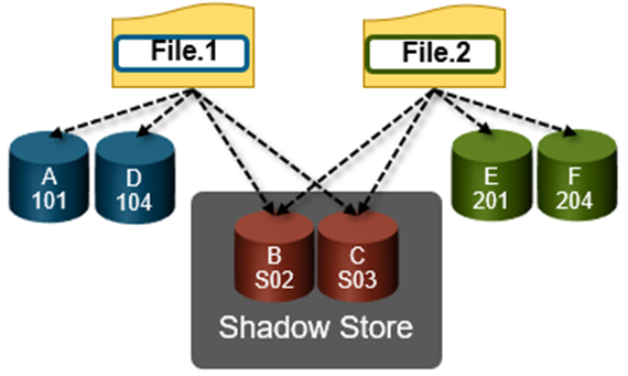
In-line dedupe samples every whole block that is written and handles each block independently, so it can aggressively locate block duplicity. If a contiguous run of matching blocks is detected, in-line dedupe merges the results into regions and processes them efficiently.
In-line dedupe also detects dedupe opportunities from the read path, and blocks are hashed as they are read into L1 cache and inserted into the index. If an existing entry exists for that hash, in-line dedupe knows there is a block-sharing opportunity between the block it just read and the one previously indexed. It combines that information and queues a request to an asynchronous dedupe worker thread. As such, it is possible to deduplicate a data set purely by reading it all. To help mitigate the performance impact, the hashing is performed out-of-band in the prefetch path, rather than in the latency-sensitive read path.
The original in-line dedupe control path design had its limitations, since it did not provide gconfig control settings for the default-disabled in-line dedupe. The previous control-path logic had no gconfig control settings for default-disabled in-line dedupe. But in OneFS 9.4, there are now two separate features that interact together to distinguish between a new cluster or an upgrade to an existing cluster configuration:
For the first feature, upon upgrade to 9.4 on an existing cluster, if there is no in-line dedupe config present, the upgrade explicitly sets it to disabled in gconfig. This has no effect on an existing cluster since it’s already disabled. Similarly, if the upgrading cluster already has an existing in-line dedupe setting in gconfig, OneFS takes no action.
For the other half of the functionality, when booting OneFS 9.4, a node looks in gconfig to see if there’s an in-line dedupe setting. If no config is present, OneFS enables it by default. Therefore, new OneFS 9.4 clusters automatically enable dedupe, and existing clusters retain their legacy setting upon upgrade.
Since the in-line dedupe configuration is binary (either on or off across a cluster), you can easily control it manually through the OneFS command line interface (CLI). As such, the isi dedupe inline settings modify CLI command can either enable or disable dedupe at will—before, during, or after the upgrade. It doesn’t matter.
For example, you can globally disable in-line dedupe and verify it using the following CLI command:
# isi dedupe inline settings viewMode: enabled# isi dedupe inline settings modify –-mode disabled # isi dedupe inline settings view Mode: disabled
Similarly, the following syntax enables in-line dedupe:
# isi dedupe inline settings view Mode: disabled # isi dedupe inline settings modify –-mode enabled # isi dedupe inline settings view Mode: enabled
While there are no visible userspace changes when files are deduplicated, if deduplication has occurred, both the disk usage and the physical blocks metrics reported by the isi get –DD CLI command are reduced. Also, at the bottom of the command’s output, the logical block statistics report the number of shadow blocks. For example:
Metatree logical blocks: zero=260814 shadow=362 ditto=0 prealloc=0 block=2 compressed=0
In-line dedupe can also be paused from the CLI:
# isi dedupe inline settings modify –-mode paused # isi dedupe inline settings view Mode: paused
However, it’s worth noting that this global setting states what you’d like to happen, after which each node attempts to enact the new configuration. However, it can’t guarantee the change, because not all node types support in-line dedupe. For example, the following output is from a heterogenous cluster with an F200 three-node pool supporting in-line dedupe, and an H400 four-node pool not supporting it.
Here, we can see that in-line dedupe is globally enabled on the cluster:
# isi dedupe inline settings view Mode: enabled
However, you can use the isi_for_array isi_inline_dedupe_status command to display the actual setting and state of each node:
# isi dedupe inline settings view Mode: enabled # isi_for_array -s isi_inline_dedupe_status 1: OK Node setting enabled is correct 2: OK Node setting enabled is correct 3: OK Node setting enabled is correct 4: OK Node does not support inline dedupe and current is disabled 5: OK Node does not support inline dedupe and current is disabled 6: OK Node does not support inline dedupe and current is disabled 7: OK Node does not support inline dedupe and current is disabled
Also, any changes to the dedupe configuration are also logged to /var/log/messages, you can find them by grepping for inline_dedupe.
In a nutshell, in-line compression has always been enabled by default since its introduction in OneFS 8.1.3. For new clusters running 9.4 and above, in-line dedupe is on by default. For clusters running 9.3 and earlier, in-line dedupe remains disabled by default. And existing clusters that upgrade to 9.4 will not see any change to their current in-line dedupe config during upgrade.
And here’s the OneFS in-line data reduction platform support matrix for good measure:
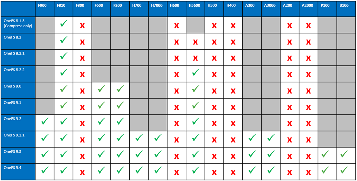

PowerScale Update: QLC Support, Incredible Performance and TCO
Mon, 02 May 2022 15:50:26 -0000
|Read Time: 0 minutes
Dell PowerScale is known for its exceptional feature set, which offers scalability, flexibility and simplicity. Our customers frequently start with one workload such as file share consolidation or mixed media storage and then scale-out OneFS to support all types of workloads leveraging the simple, cloud-like single pool storage architecture.
To provide our customers with even more flexibility and choice, this summer we will introduce new Quad-level cell (QLC) flash memory 15TB and 30TB drives for our PowerScale F900 and F600 all-flash models. And we are seeing an up to 25% or more better performance for streaming reads, depending on workload, with all-flash nodes in the subsequent PowerScale OneFS release.1
Delivering latest-generation, Gen 2 QLC Support
With the many important and needed improvements in reliability and performance delivered by Gen 2 QLC technology, we’ve reached the optimal point in the development of QLC technology to deliver QLC flash drives for the PowerScale F900 and F600 all-flash models. These new QLC drives, supported by the currently shipping OneFS 9.4 release, will offer our customers incredible economics for fast NAS workloads that need both performance and capacity – such as financial modeling, media and entertainment, artificial intelligence (AI), machine learning (ML), and deep learning (DL). With 30TB QLC drive support, we are able to increase the raw density per node to 720TB for PowerScale F900 and 240TB for PowerScale F600 – and lower the cost of flash for our customers.
OneFS.next Performance Boost
Another emerging PowerScale feature of interest, targeted for an upcoming OneFS software release, is a major performance enhancement that will unlock streaming read throughput gains of up to 25% or more, depending on workload, for our flagship all-flash PowerScale F-series NVMe platforms.1 This significant performance boost will be of particular benefit to customers with high throughput, streaming read-heavy workloads, such as media and entertainment hi-res playout, ADAS for the automotive industry, and financial services high frequency, complex trading queries. Pairing nicely with the aforementioned performance boost is PowerScale’s support for NFS over RDMA (NFSoRDMA), which can further accelerate high throughput performance, especially for single connection and read intensive workloads such as machine learning – while also dramatically reducing both cluster and client CPU utilization.
All Together Now
Further, these drives become part of the overall life cycle management system within OneFS. This gives PowerScale a major TCO advantage over the competition. In harmony with this forthcoming streaming performance enhancement, OneFS’s non-disruptive upgrade framework will enable existing PowerScale environments to seamlessly and non-disruptively up-rev their cluster software and enjoy this major performance boost on PowerScale F900 and F600 pools – free from any hardware addition, modification, reconfiguration, intervention, or downtime.
These are just a few of the exciting things we have in the works for PowerScale, the world’s most flexible scale-out NAS solution.2
If you are attending Dell Technologies World, check out these sessions for more about our PowerScale innovations.
- Discover the latest Enhancements to PowerScale for Unstructured Storage Solutions
- May 3 at 12 p.m. in Lando 4205
- Improve Threat Detection, Isolation and Data Recovery with PowerScale Cyber Protection
- May 3 or May 4 at 3 p.m. in Lando 4205
- Top 10 Tips to Get More out of Your PowerScale Investment
- May 3 at 12 p.m. in Palazzo I
- Ask the Experts: Harness the Power of Your Unstructured Data
- May 4 at 3 p.m. in Zeno 4601
_________________
1 Based on Dell internal testing, April 2022. Actual results will vary.
2 Based on internal Dell analysis of publicly available information, August 2021.
Author: David Noy, Vice President of Product Management, Unstructured Data Solutions and Data Protection Solutions, Dell Technologies

Announcing PowerScale OneFS 9.4!
Fri, 28 Apr 2023 19:52:18 -0000
|Read Time: 0 minutes
Arriving in time for Dell Technologies World 2022, the new PowerScale OneFS 9.4 release shipped on Monday 4th April 2022.
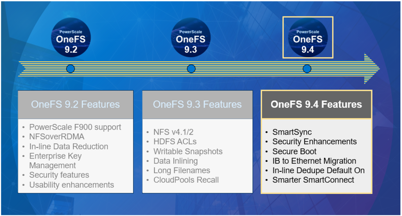
OneFS 9.4 brings with it a wide array of new features and functionality, including:
Feature | Description |
SmartSync Data Mover |
|
IB to Ethernet Backend Migration |
|
Secure Boot |
|
Smarter SmartConnect Diagnostics |
|
In-line Dedupe |
|
Healthcheck Auto-updates |
|
CloudIQ Protocol Statistics |
|
SRS Alerts and CELOG Event Limiting |
|
CloudPools Statistics |
|
We’ll be taking a deeper look at some of these new features in blog articles over the course of the next few weeks.
Meanwhile, the new OneFS 9.4 code is available for download on the Dell Online Support site, in both upgrade and reimage file formats.
Enjoy your OneFS 9.4 experience!
Author: Nick Trimbee

OneFS Caching Hierarchy
Tue, 22 Mar 2022 20:05:56 -0000
|Read Time: 0 minutes
Caching occurs in OneFS at multiple levels, and for a variety of types of data. For this discussion we’ll concentrate on the caching of file system structures in main memory and on SSD.
OneFS’ caching infrastructure design is based on aggregating each individual node’s cache into one cluster wide, globally accessible pool of memory. This is done by using an efficient messaging system, which allows all the nodes’ memory caches to be available to each and every node in the cluster.
For remote memory access, OneFS uses the Sockets Direct Protocol (SDP) over an Ethernet or Infiniband (IB) backend interconnect on the cluster. SDP provides an efficient, socket-like interface between nodes which, by using a switched star topology, ensures that remote memory addresses are only ever one hop away. While not as fast as local memory, remote memory access is still very fast due to the low latency of the backend network.
OneFS uses up to three levels of read cache, plus an NVRAM-backed write cache, or write coalescer. The first two types of read cache, level 1 (L1) and level 2 (L2), are memory (RAM) based, and analogous to the cache used in CPUs. These two cache layers are present in all PowerScale storage nodes. An optional third tier of read cache, called SmartFlash, or Level 3 cache (L3), is also configurable on nodes that contain solid state drives (SSDs). L3 cache is an eviction cache that is populated by L2 cache blocks as they are aged out from memory.
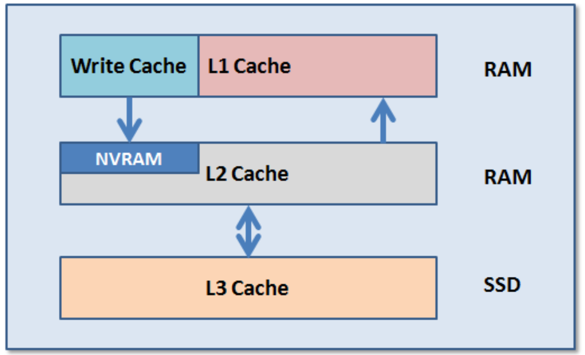
The OneFS caching subsystem is coherent across the cluster. This means that if the same content exists in the private caches of multiple nodes, this cached data is consistent across all instances. For example, consider the following scenario:
- Node 2 and Node 4 each have a copy of data located at an address in shared cache.
- Node 4, in response to a write request, invalidates node 2’s copy.
- Node 4 then updates the value.
- Node 2 must re-read the data from shared cache to get the updated value.
OneFS uses the MESI Protocol to maintain cache coherency, implementing an “invalidate-on-write” policy to ensure that all data is consistent across the entire shared cache. The various states that in-cache data can take are:
M – Modified: The data exists only in local cache, and has been changed from the value in shared cache. Modified data is referred to as ‘dirty’.
E – Exclusive: The data exists only in local cache, but matches what is in shared cache. This data referred to as ‘clean’.
S – Shared: The data in local cache may also be in other local caches in the cluster.
I – Invalid: A lock (exclusive or shared) has been lost on the data.
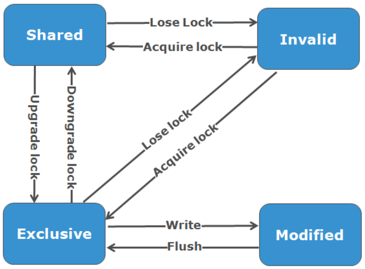
L1 cache, or front-end cache, is memory that is nearest to the protocol layers (such as NFS, SMB, and so on) used by clients, or initiators, connected to that node. The main task of L1 is to prefetch data from remote nodes. Data is pre-fetched per file, and this is optimized to reduce the latency associated with the nodes’ IB back-end network. Because the IB interconnect latency is relatively small, the size of L1 cache, and the typical amount of data stored per request, is less than L2 cache.
L1 is also known as remote cache because it contains data retrieved from other nodes in the cluster. It is coherent across the cluster, but is used only by the node on which it resides, and is not accessible by other nodes. Data in L1 cache on storage nodes is aggressively discarded after it is used. L1 cache uses file-based addressing, in which data is accessed by means of an offset into a file object. The L1 cache refers to memory on the same node as the initiator. It is only accessible to the local node, and typically the cache is not the primary copy of the data. This is analogous to the L1 cache on a CPU core, which may be invalidated as other cores write to main memory. L1 cache coherency is managed using a MESI-like protocol using distributed locks, as described above.
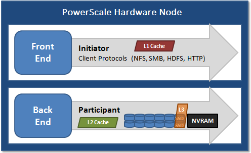
L2, or back-end cache, refers to local memory on the node on which a particular block of data is stored. L2 reduces the latency of a read operation by not requiring a seek directly from the disk drives. As such, the amount of data prefetched into L2 cache for use by remote nodes is much greater than that in L1 cache.
L2 is also known as local cache because it contains data retrieved from disk drives located on that node and then made available for requests from remote nodes. Data in L2 cache is evicted according to a Least Recently Used (LRU) algorithm. Data in L2 cache is addressed by the local node using an offset into a disk drive which is local to that node. Because the node knows where the data requested by the remote nodes is located on disk, this is a very fast way of retrieving data destined for remote nodes. A remote node accesses L2 cache by doing a lookup of the block address for a particular file object. As described above, there is no MESI invalidation necessary here and the cache is updated automatically during writes and kept coherent by the transaction system and NVRAM.
L3 cache is a subsystem that caches evicted L2 blocks on a node. Unlike L1 and L2, not all nodes or clusters have an L3 cache, because it requires solid state drives (SSDs) to be present and exclusively reserved and configured for caching use. L3 serves as a large, cost-effective way of extending a node’s read cache from gigabytes to terabytes. This allows clients to retain a larger working set of data in cache, before being forced to retrieve data from higher latency spinning disk. The L3 cache is populated with “interesting” L2 blocks dropped from memory by L2’s least recently used cache eviction algorithm. Unlike RAM based caches, because L3 is based on persistent flash storage, once the cache is populated, or warmed, it’s highly durable and persists across node reboots, and so on. L3 uses a custom log-based file system with an index of cached blocks. The SSDs provide very good random read access characteristics, such that a hit in L3 cache is not that much slower than a hit in L2.
To use multiple SSDs for cache effectively and automatically, L3 uses a consistent hashing approach to associate an L2 block address with one L3 SSD. In the event of an L3 drive failure, a portion of the cache will obviously disappear, but the remaining cache entries on other drives will still be valid. Before a new L3 drive can be added to the hash, some cache entries must be invalidated.
OneFS also uses a dedicated inode cache in which recently requested inodes are kept. The inode cache frequently has a large impact on performance, because clients often cache data, and many network I/O activities are primarily requests for file attributes and metadata, which can be quickly returned from the cached inode.
OneFS provides tools to accurately assess the performance of the various levels of cache at a point in time. These cache statistics can be viewed from the OneFS CLI using the isi_cache_stats command. Statistics for L1, L2, and L3 cache are displayed for both data and metadata. For example:
# isi_cache_stats Totals l1_data: a 224G 100% r 226G 100% p 318M 77%, l1_encoded: a 0.0B 0% r 0.0B 0% p 0.0B 0%, l1_meta: r 4.5T 99% p 152K 48%, l2_data: r 1.2G 95% p 115M 79%, l2_meta: r 27G 72% p 28M 3%, l3_data: r 0.0B 0% p 0.0B 0%, l3_meta: r 8G 99% p 0.0B 0%
For more detailed and formatted output, a verbose option of the command is available using the ‘isi_cache_stats -v’ option.
It’s worth noting that for L3 cache, the prefetch statistics will always read zero, since it’s a pure eviction cache and does not use data or metadata prefetch.
Due to balanced data distribution, automatic rebalancing, and distributed processing, OneFS is able to leverage additional CPUs, network ports, and memory as the system grows. This also allows the caching subsystem (and, by virtue, throughput and IOPS) to scale linearly with the cluster size.
Author: Nick Trimbee

OneFS Endurant Cache
Tue, 22 Mar 2022 18:27:04 -0000
|Read Time: 0 minutes
My earlier blog post on multi-threaded I/O generated several questions on synchronous writes in OneFS. So, this seemed like a useful topic to explore in a bit more detail.
OneFS natively provides a caching mechanism for synchronous writes – or writes that require a stable write acknowledgement to be returned to a client. This functionality is known as the Endurant Cache, or EC.
The EC operates in conjunction with the OneFS write cache, or coalescer, to ingest, protect, and aggregate small synchronous NFS writes. The incoming write blocks are staged to NVRAM, ensuring the integrity of the write, even during the unlikely event of a node’s power loss. Furthermore, EC also creates multiple mirrored copies of the data, further guaranteeing protection from single node and, if desired, multiple node failures.
EC improves the latency associated with synchronous writes by reducing the time to acknowledgement back to the client. This process removes the Read-Modify-Write (R-M-W) operations from the acknowledgement latency path, while also leveraging the coalescer to optimize writes to disk. EC is also tightly coupled with OneFS’ multi-threaded I/O (Multi-writer) process, to support concurrent writes from multiple client writer threads to the same file. And the design of EC ensures that the cached writes do not impact snapshot performance.
The endurant cache uses write logging to combine and protect small writes at random offsets into 8KB linear writes. To achieve this, the writes go to special mirrored files, or ‘Logstores’. The response to a stable write request can be sent once the data is committed to the logstore. Logstores can be written to by several threads from the same node and are highly optimized to enable low-latency concurrent writes.
Note that if a write uses the EC, the coalescer must also be used. If the coalescer is disabled on a file, but EC is enabled, the coalescer will still be active with all data backed by the EC.
So what exactly does an endurant cache write sequence look like?
Say an NFS client wishes to write a file to a PowerScale cluster over NFS with the O_SYNC flag set, requiring a confirmed or synchronous write acknowledgement. Here is the sequence of events that occurs to facilitate a stable write.
1. A client, connected to node 3, begins the write process sending protocol level blocks. 4K is the optimal block size for the endurant cache.
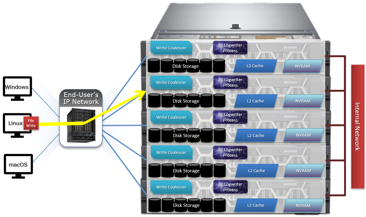
2. The NFS client’s writes are temporarily stored in the write coalescer portion of node 3’s RAM. The Write Coalescer aggregates uncommitted blocks so that the OneFS can, ideally, write out full protection groups where possible, reducing latency over protocols that allow “unstable” writes. Writing to RAM has far less latency that writing directly to disk.
3. Once in the write coalescer, the endurant cache log-writer process writes mirrored copies of the data blocks in parallel to the EC Log Files.
The protection level of the mirrored EC log files is the same as that of the data being written by the NFS client.
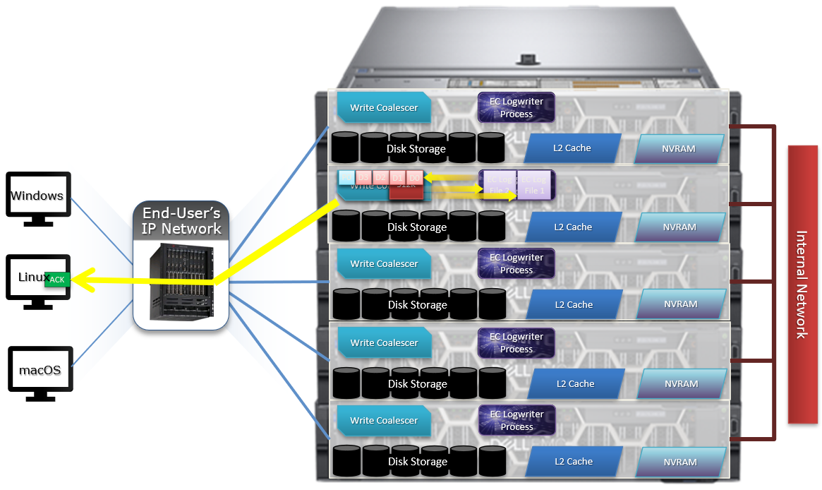
4. When the data copies are received into the EC Log Files, a stable write exists and a write acknowledgement (ACK) is returned to the NFS client confirming the stable write has occurred. The client assumes the write is completed and can close the write session.
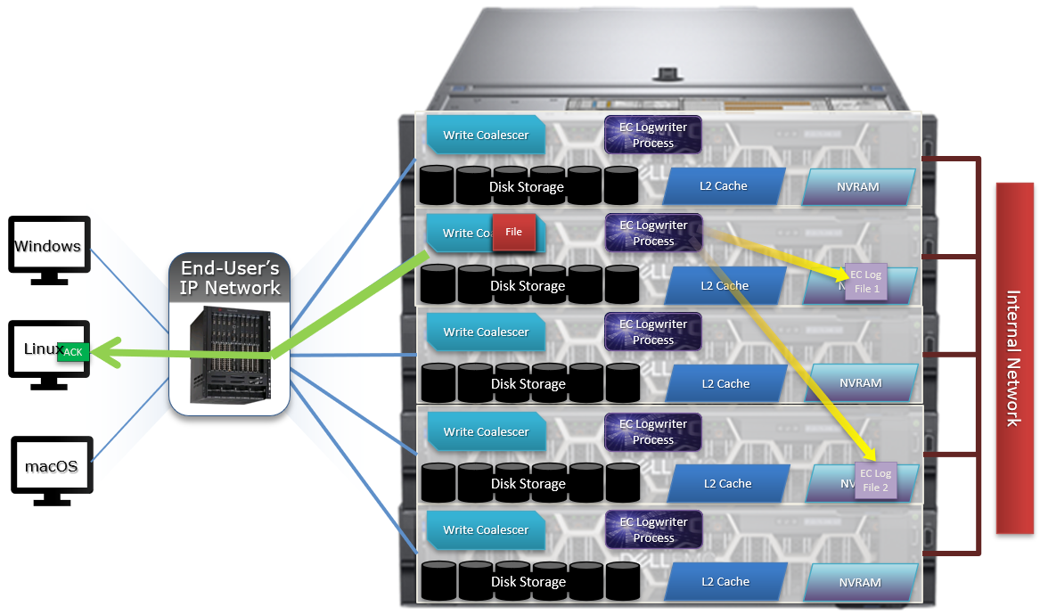
5. The write coalescer then processes the file just like a non-EC write at this point. The write coalescer fills and is routinely flushed as required as an asynchronous write to the block allocation manager (BAM) and the BAM safe write (BSW) path processes.
6. The file is split into 128K data stripe units (DSUs), parity protection (FEC) is calculated, and FEC stripe units (FSUs) are created.
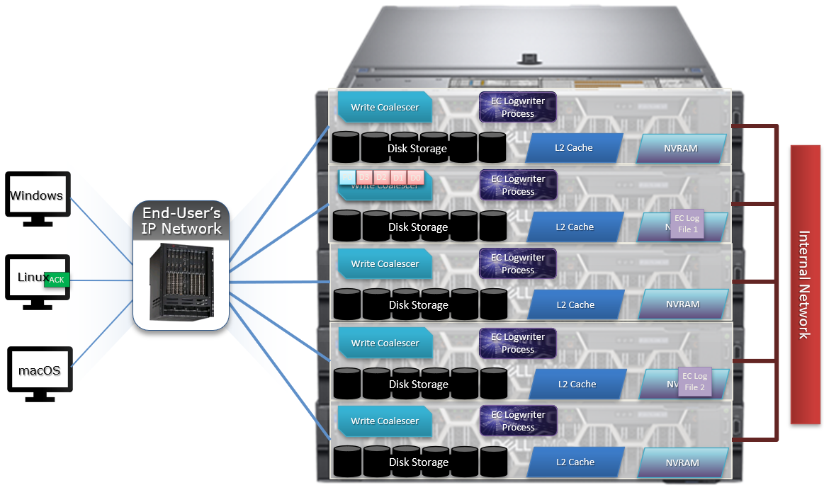
7. The layout and write plan is then determined, and the stripe units are written to their corresponding nodes’ L2 Cache and NVRAM. The EC logfiles are cleared from NVRAM at this point. OneFS uses a Fast Invalid Path process to de-allocate the EC Log Files from NVRAM.
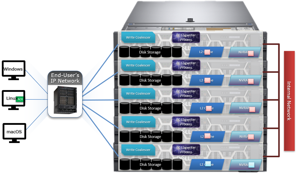
8. Stripe Units are then flushed to physical disk.
9. Once written to physical disk, the data stripe Unit (DSU) and FEC stripe unit (FSU) copies created during the write are cleared from NVRAM but remain in L2 cache until flushed to make room for more recently accessed data.
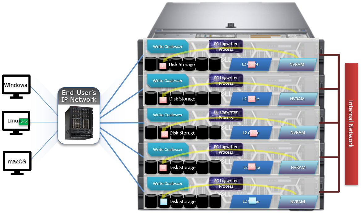
As far as protection goes, the number of logfile mirrors created by EC is always one more than the on-disk protection level of the file. For example:
File Protection Level | Number of EC Mirrored Copies |
+1n | 2 |
2x | 3 |
+2n | 3 |
+2d:1n | 3 |
+3n | 4 |
+3d:1n | 4 |
+4n | 5 |
The EC mirrors are only used if the initiator node is lost. In the unlikely event that this occurs, the participant nodes replay their EC journals and complete the writes.
If the write is an EC candidate, the data remains in the coalescer, an EC write is constructed, and the appropriate coalescer region is marked as EC. The EC write is a write into a logstore (hidden mirrored file) and the data is placed into the journal.
Assuming the journal is sufficiently empty, the write is held there (cached) and only flushed to disk when the journal is full, thereby saving additional disk activity.
An optimal workload for EC involves small-block synchronous, sequential writes – something like an audit or redo log, for example. In that case, the coalescer will accumulate a full protection group’s worth of data and be able to perform an efficient FEC write.
The happy medium is a synchronous small block type load, particularly where the I/O rate is low and the client is latency-sensitive. In this case, the latency will be reduced and, if the I/O rate is low enough, it won’t create serious pressure.
The undesirable scenario is when the cluster is already spindle-bound and the workload is such that it generates a lot of journal pressure. In this case, EC is just going to aggravate things.
So how exactly do you configure the endurant cache?
Although on by default, setting the efs.bam.ec.mode sysctl to value ‘1’ will enable the Endurant Cache:
# isi_sysctl_cluster efs.bam.ec.mode=1
EC can also be enabled and disabled per directory:
# isi set -c [on|off|endurant_all|coal_only] <directory_name>
To enable the coalescer but switch off EC, run:
# isi set -c coal_only
And to disable the endurant cache completely:
# isi_for_array –s isi_sysctl_cluster efs.bam.ec.mode=0
A return value of zero on each node from the following command will verify that EC is disabled across the cluster:
# isi_for_array –s sysctl efs.bam.ec.stats.write_blocks efs.bam.ec.stats.write_blocks: 0
If the output to this command is incrementing, EC is delivering stable writes.
Be aware that if the Endurant Cache is disabled on a cluster, the sysctl efs.bam.ec.stats.write_blocks output on each node will not return to zero, because this sysctl is a counter, not a rate. These counters won’t reset until the node is rebooted.
As mentioned previously, EC applies to stable writes, namely:
- Writes with O_SYNC and/or O_DIRECT flags set
- Files on synchronous NFS mounts
When it comes to analyzing any performance issues involving EC workloads, consider the following:
- What changed with the workload?
- If upgrading OneFS, did the prior version also have EC enabled?
If the workload has moved to new cluster hardware:
- Does the performance issue occur during periods of high CPU utilization?
- Which part of the workload is creating a deluge of stable writes?
- Was there a large change in spindle or node count?
- Has the OneFS protection level changed?
- Is the SSD strategy the same?
Disabling EC is typically done cluster-wide and this can adversely impact certain workflow elements. If the EC load is localized to a subset of the files being written, an alternative way to reduce the EC heat might be to disable the coalescer buffers for some particular target directories, which would be a more targeted adjustment. This can be configured using the isi set –c off command.
One of the more likely causes of performance degradation is from applications aggressively flushing over-writes and, as a result, generating a flurry of ‘commit’ operations. This can generate heavy read/modify/write (r-m-w) cycles, inflating the average disk queue depth, and resulting in significantly slower random reads. The isi statistics protocol CLI command output will indicate whether the ‘commit’ rate is high.
It’s worth noting that synchronous writes do not require using the NFS ‘sync’ mount option. Any programmer who is concerned with write persistence can simply specify an O_FSYNC or O_DIRECT flag on the open() operation to force synchronous write semantics for that file handle. With Linux, writes using O_DIRECT will be separately accounted for in the Linux ‘mountstats’ output. Although it’s almost exclusively associated with NFS, the EC code is actually protocol-agnostic. If writes are synchronous (write-through) and are either misaligned or smaller than 8k, they have the potential to trigger EC, regardless of the protocol.
The endurant cache can provide a significant latency benefit for small (such as 4K), random synchronous writes – albeit at a cost of some additional work for the system.
However, it’s worth bearing the following caveats in mind:
- EC is not intended for more general purpose I/O.
- There is a finite amount of EC available. As load increases, EC can potentially ‘fall behind’ and end up being a bottleneck.
- Endurant Cache does not improve read performance, since it’s strictly part of the write process.
- EC will not increase performance of asynchronous writes – only synchronous writes.
Author: Nick Trimbee

OneFS Writes
Mon, 14 Mar 2022 23:13:12 -0000
|Read Time: 0 minutes
OneFS runs equally across all the nodes in a cluster such that no one node controls the cluster and all nodes are true peers. Looking from a high-level at the components within each node, the I/O stack is split into a top layer, or initiator, and a bottom layer, or participant. This division is used as a logical model for the analysis of OneFS’ read and write paths.
At a physical-level, CPUs and memory cache in the nodes are simultaneously handling initiator and participant tasks for I/O taking place throughout the cluster. There are caches and a distributed lock manager that are excluded from the diagram below for simplicity’s sake.
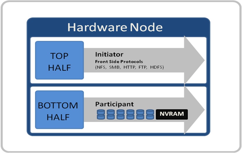
When a client connects to a node to write a file, it is connecting to the top half or initiator of that node. Files are broken into smaller logical chunks called stripes before being written to the bottom half or participant of a node (disk). Failure-safe buffering using a write coalescer is used to ensure that writes are efficient and read-modify-write operations are avoided. The size of each file chunk is referred to as the stripe unit size. OneFS stripes data across all nodes and protects the files, directories, and associated metadata via software erasure-code or mirroring.
OneFS determines the appropriate data layout to optimize for storage efficiency and performance. When a client connects to a node, that node’s initiator acts as the ‘captain’ for the write data layout of that file. Data, erasure code (FEC) protection, metadata, and inodes are all distributed on multiple nodes, and spread across multiple drives within nodes. The following figure shows a file write occurring across all nodes in a three node cluster.
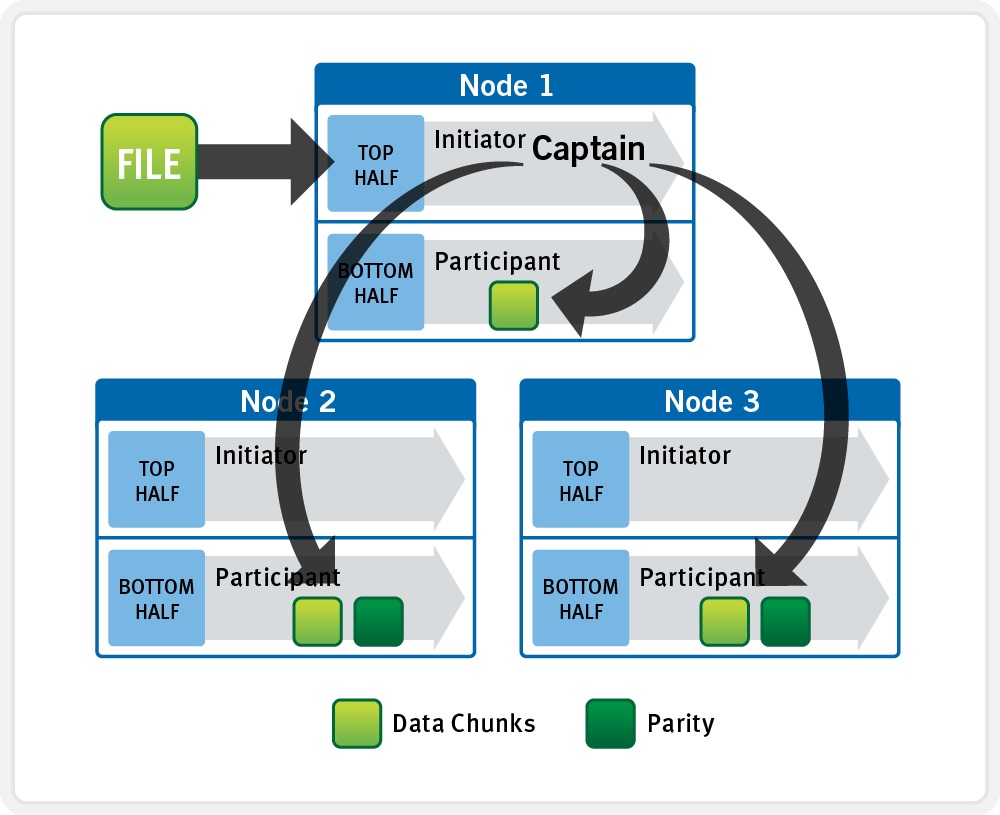
OneFS uses a cluster’s Ethernet or Infiniband back-end network to allocate and automatically stripe data across all nodes. As data is written, it’s also protected at the specified level.
When writes take place, OneFS divides data out into atomic units called protection groups. Redundancy is built into protection groups, such that if every protection group is safe, then the entire file is safe. For files protected by FEC, a protection group consists of a series of data blocks as well as a set of parity blocks for reconstruction of the data blocks in the event of drive or node failure. For mirrored files, a protection group consists of all of the mirrors of a set of blocks.
OneFS is capable of switching the type of protection group used in a file dynamically, as it is writing. This allows the cluster to continue without blocking in situations when temporary node failure prevents the desired level of parity protection from being applied. In this case, mirroring can be used temporarily to allow writes to continue. When nodes are restored to the cluster, these mirrored protection groups are automatically converted back to FEC protected.
During a write, data is broken into stripe units and these are spread across multiple nodes as a protection group. As data is being laid out across the cluster, erasure codes or mirrors, as required, are distributed within each protection group to ensure that files are protected at all times.
One of the key functions of the OneFS AutoBalance job is to reallocate and balance data and, where possible, make storage space more usable and efficient. In most cases, the stripe width of larger files can be increased to take advantage of new free space, as nodes are added, and to make the on-disk layout more efficient.
The initiator top half of the ‘captain’ node uses a modified two-phase commit (2PC) transaction to safely distribute writes across the cluster, as follows:
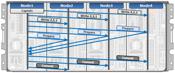
Every node that owns blocks in a particular write operation is involved in a two-phase commit mechanism, which relies on NVRAM for journaling all the transactions that are occurring across every node in the storage cluster. Using multiple nodes’ NVRAM in parallel allows for high-throughput writes, while maintaining data safety against all manner of failure conditions, including power failures. If a node should fail mid-transaction, the transaction is restarted instantly without that node involved. When the node returns, it simply replays its journal from NVRAM.
In a write operation, the initiator also orchestrates the layout of data and metadata, the creation of erasure codes, and lock management and permissions control. OneFS can also optimize layout decisions to better suit the workflow. These access patterns, which can be configured at a per-file or directory level, include:
Concurrency: Optimizes for current load on the cluster, featuring many simultaneous clients.
Streaming: Optimizes for high-speed streaming of a single file, for example to enable very fast reading with a single client.
Random: Optimizes for unpredictable access to the file, by adjusting striping and disabling the use of prefetch.
Author: Nick Trimbee

OneFS File Locking and Concurrent Access
Mon, 14 Mar 2022 23:03:37 -0000
|Read Time: 0 minutes
There has been a bevy of recent questions around how OneFS allows various clients attached to different nodes of a cluster to simultaneously read from and write to the same file. So it seemed like a good time for a quick refresher on some of the concepts and mechanics behind OneFS concurrency and distributed locking.
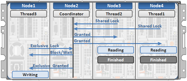
File locking is the mechanism that allows multiple users or processes to access data concurrently and safely. For reading data, this is a fairly straightforward process involving shared locks. With writes, however, things become more complex and require exclusive locking, because data must be kept consistent.
OneFS has a fully distributed lock manager that marshals locks on data across all the nodes in a storage cluster. This locking manager is highly extensible and allows for multiple lock types to support both file system locks, as well as cluster-coherent protocol-level locks, such as SMB share mode locks or NFS advisory-mode locks. OneFS supports delegated locks such as SMB oplocks and NFSv4 delegations.
Every node in a cluster can act as coordinator for locking resources, and a coordinator is assigned to lockable resources based upon a hashing algorithm. This selection algorithm is designed so that the coordinator almost always ends up on a different node than the initiator of the request. When a lock is requested for a file, it can either be a shared lock or an exclusive lock. A shared lock is primarily used for reads and allows multiple users to share the lock simultaneously. An exclusive lock, on the other hand, allows only one user access to the resource at any given moment, and is typically used for writes. Exclusive lock types include:
Mark Lock: An exclusive lock resource used to synchronize the marking and sweeping processes for the Collect job engine job.
Snapshot Lock: As the name suggests, the exclusive snapshot lock that synchronizes the process of creating and deleting snapshots.
Write Lock: An exclusive lock that’s used to quiesce writes for particular operations, including snapshot creates, non-empty directory renames, and marks.
The OneFS locking infrastructure has its own terminology, and includes the following definitions:
Domain: Refers to the specific lock attributes (recursion, deadlock detection, memory use limits, and so on) and context for a particular lock application. There is one definition of owner, resource, and lock types, and only locks within a particular domain might conflict.
Lock Type: Determines the contention among lockers. A shared or read lock does not contend with other types of shared or read locks, while an exclusive or write lock contends with all other types. Lock types include:
- Advisory
- Anti-virus
- Data
- Delete
- LIN
- Mark
- Oplocks
- Quota
- Read
- Share Mode
- SMB byte-range
- Snapshot
- Write
Locker: Identifies the entity that acquires a lock.
Owner: A locker that has successfully acquired a particular lock. A locker may own multiple locks of the same or different type as a result of recursive locking.
Resource: Identifies a particular lock. Lock acquisition only contends on the same resource. The resource ID is typically a LIN to associate locks with files.
Waiter: Has requested a lock but has not yet been granted or acquired it.
Here’s an example of how threads from different nodes could request a lock from the coordinator:

- Node 2 is selected as the lock coordinator of these resources.
- Thread 1 from Node 4 and thread 2 from Node 3 request a shared lock on a file from Node 2 at the same time.
- Node 2 checks if an exclusive lock exists for the requested file.
- If no exclusive locks exist, Node 2 grants thread 1 from Node 4 and thread 2 from Node 3 shared locks on the requested file.
- Node 3 and Node 4 are now performing a read on the requested file.
- Thread 3 from Node 1 requests an exclusive lock for the same file as being read by Node 3 and Node 4.
- Node 2 checks with Node 3 and Node 4 if the shared locks can be reclaimed.
- Node 3 and Node 4 are still reading so Node 2 asks thread 3 from Node 1 to wait for a brief instant.
- Thread 3 from Node 1 blocks until the exclusive lock is granted by Node 2 and then completes the write operation.
Author: Nick Trimbee

OneFS Time Synchronization and NTP
Fri, 11 Mar 2022 16:08:05 -0000
|Read Time: 0 minutes
OneFS provides a network time protocol (NTP) service to ensure that all nodes in a cluster can easily be synchronized to the same time source. This service automatically adjusts a cluster’s date and time settings to that of one or more external NTP servers.
You can perform NTP configuration on a cluster using the isi ntp command line (CLI) utility, rather than modifying the nodes’ /etc/ntp.conf files manually. The syntax for this command is divided into two parts: servers and settings. For example:
# isi ntp settings
Description:
View and modify cluster NTP configuration.
Required Privileges:
ISI_PRIV_NTP
Usage:
isi ntp settings <action>
[--timeout <integer>]
[{--help | -h}]
Actions:
modify Modify cluster NTP configuration.
view View cluster NTP configuration.
Options:
Display Options:
--timeout <integer>
Number of seconds for a command timeout (specified as 'isi --timeout NNN
<command>').
--help | -h
Display help for this command.There is also an isi_ntp_config CLI command available in OneFS that provides a richer configuration set and combines the server and settings functionality:
Usage: isi_ntp_config COMMAND [ARGUMENTS ...] Commands: help Print this help and exit. list List all configured info. add server SERVER [OPTION] Add SERVER to ntp.conf. If ntp.conf is already configured for SERVER, the configuration will be replaced. You can specify any server option. See NTP.CONF(5) delete server SERVER Remove server configuration for SERVER if it exists. add exclude NODE [NODE...] Add NODE (or space separated nodes) to NTP excluded entry. Excluded nodes are not used for NTP communication with external NTP servers. delete exclude NODE [NODE...] Delete NODE (or space separated Nodes) from NTP excluded entry. keyfile KEYFILE_PATH Specify keyfile path for NTP auth. Specify "" to clear value. KEYFILE_PATH has to be a path under /ifs. chimers [COUNT | "default"] Display or modify the number of chimers NTP uses. Specify "default" to clear the value.
By default, if the cluster has more than three nodes, three of the nodes are selected as chimers. Chimers are nodes which can contact the external NTP servers. If the cluster consists of three nodes or less, only one node is selected as a chimer. If no external NTP server is set, they use the local clock instead. The other non-chimer nodes use the chimer nodes as their NTP servers. The chimer nodes are selected by the lowest node number which is not excluded from chimer duty.
If a node is configured as a chimer. its /etc/ntp.conf entry will resemble: # This node is one of the 3 chimer nodes that can contact external NTP # servers. The non-chimer nodes will use this node as well as the other # chimers as their NTP servers. server time.isilon.com # The other chimer nodes on this cluster: server 192.168.10.150 iburst server 192.168.10.151 iburst # If none or bad connection to external servers this node may become # the time server for this cluster. The system clock will be a time # source and run at a high stratum
Besides managing NTP servers and authentication, you can exclude individual nodes from communicating with external NTP servers.
The local clock of the node is set as an NTP server at a high stratum level. In NTP, a server with lower stratum number is preferred, so if an external NTP server is set, the system prefers an external time server if configured. The stratum level for the chimer is determined by the chimer number. The first chimer is set to stratum 9, the second to stratum 11, and the others continue to increment the stratum number by 2. This is so the non-chimer nodes prefer to get the time from the first chimer if available.
For a non-chimer node, its /etc/ntp.conf entry will resemble:
# This node is _not_ one of the 3 chimer nodes that can contact external # NTP servers. These are the cluster's chimer nodes: server 192.168.10.149 iburst true server 192.168.10.150 iburst true server 192.168.10.151 iburst true
When configuring NTP on a cluster, you can specify more than one NTP server to synchronize the system time from. This ability allows for full redundancy of ysnc targets. The cluster periodically contacts the server or servers and adjusts the time, date or both as necessary, based on the information it receives.
You can use the isi_ntp_config CLI command to configure which NTP servers a cluster will reference. For example, the following syntax adds the server time.isilon.com:
# isi_ntp_config add server time.isilon.com
Alternatively, you can manage the NTP configuration from the WebUI by going to Cluster Management > General Settings > NTP.
NTP also provides basic authentication-based security using symmetrical keys, if preferred.
If no NTP servers are available, Windows Active Directory (AD) can synchronize domain members to a primary clock running on the domain controller or controllers. If there are no external NTP servers configured and the cluster is joined to AD, OneFS uses the Windows domain controller as the NTP time server. If the cluster and domain time become out of sync by more than four minutes, OneFS generates an event notification.
Be aware that if the cluster and Active Directory drift out of time sync by more than five minutes, AD authentication will cease to function.
If both NTP server and domain controller are not available, you can manually set the cluster’s time, date and time zone using the isi config CLI command. For example:
1. Run the isi config command. The command-line prompt changes to indicate that you are in the isi config subsystem:
# isi config Welcome to the Isilon IQ configuration console. Copyright (c) 2001-2017 EMC Corporation. All Rights Reserved. Enter 'help' to see list of available commands. Enter 'help <command>' to see help for a specific command. Enter 'quit' at any prompt to discard changes and exit. Node build: Isilon OneFS v8.2.2 B_8_2_2(RELEASE)Node serial number: JWXER170300301 >>>
2. Specify the current date and time by running the date command. For example, the following command sets the cluster time to 9:20 AM on April 23, 2020:
>>> date 2020/04/23 09:20:00 Date is set to 2020/04/23 09:20:00
3. The help timezone command lists the available timezones. For example:
>>> help timezone timezone [<timezone identifier>] Sets the time zone on the cluster to the specified time zone. Valid time zone identifiers are: Greenwich Mean Time Eastern Time Zone Central Time Zone Mountain Time Zone Pacific Time Zone Arizona Alaska Hawaii Japan Advanced
4. To verify the currently configured time zone, run the timezone command. For example:
>>> timezone The current time zone is: Greenwich Mean Time
5. To change the time zone, enter the timezone command followed by one of the displayed options. For example, the following command changes the time zone to Alaska:
>>> timezone Alaska Time zone is set to Alaska
A message confirming the new time zone setting displays. If your preferred time zone did not display when you ran the help timezone command, enter timezone Advanced. After a warning screen displays, you will see a list of regions. When you select a region, a list of specific time zones for that region appears. Select the preferred time zone (you may need to scroll), and enter OK or Cancel until you return to the isi config prompt.
6. When done, run the commit command to save your changes and exit isi config.
>>> commit Commit succeeded.
Alternatively, you can manage these time and date parameters from the WebUI by going to Cluster Management > General Settings > Date and Time.
Author: Nick Trimbee

OneFS Multi-writer
Fri, 04 Mar 2022 21:09:19 -0000
|Read Time: 0 minutes
In one of my other blog articles, we looked at write locking and shared access in OneFS. Next, we’ll delve another layer deeper into OneFS concurrent file access.
The OneFS locking hierarchy also provides a mechanism called Multi-writer, which allows a cluster to support concurrent writes from multiple client writer threads to the same file. This granular write locking is achieved by sub-dividing the file into separate regions and granting exclusive data write locks to these individual ranges, as opposed to the entire file. This process allows multiple clients, or write threads, attached to a node to simultaneously write to different regions of the same file.
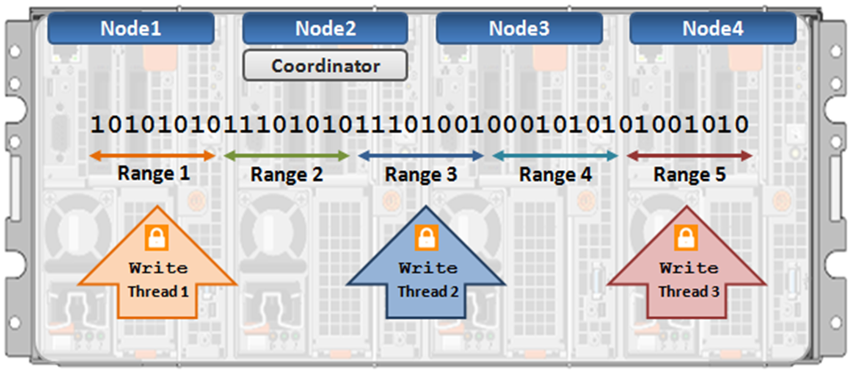
Concurrent writes to a single file need more than just supporting data locks for ranges. Each writer also needs to update a file’s metadata attributes such as timestamps or block count. A mechanism for managing inode consistency is also needed, since OneFS is based on the concept of a single inode lock per file.
In addition to the standard shared read and exclusive write locks, OneFS also provides the following locking primitives, through journal deltas, to allow multiple threads to simultaneously read or write a file’s metadata attributes:
OneFS Lock Types include:
Exclusive: A thread can read or modify any field in the inode. When the transaction is committed, the entire inode block is written to disk, along with any extended attribute blocks.
Shared: A thread can read, but not modify, any inode field.
DeltaWrite: A thread can modify any inode fields which support delta-writes. These operations are sent to the journal as a set of deltas when the transaction is committed.
DeltaRead: A thread can read any field which cannot be modified by inode deltas.
These locks allow separate threads to have a Shared lock on the same LIN, or for different threads to have a DeltaWrite lock on the same LIN. However, it is not possible for one thread to have a Shared lock and another to have a DeltaWrite. This is because the Shared thread cannot perform a coherent read of a field which is in the process of being modified by the DeltaWrite thread.
The DeltaRead lock is compatible with both the Shared and DeltaWrite lock. Typically the file system will attempt to take a DeltaRead lock for a read operation, and a DeltaWrite lock for a write, since this allows maximum concurrency, as all these locks are compatible.
Here’s what the write lock incompatibilities looks like:
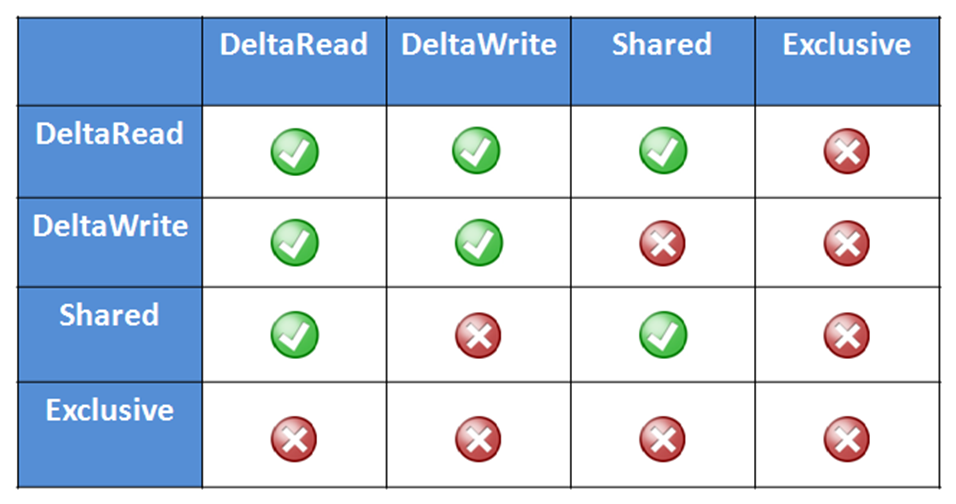
OneFS protects data by writing file blocks (restriping) across multiple drives on different nodes. The Job Engine defines a restripe set comprising jobs which involve file-system management, protection and on-disk layout. The restripe set contains the following jobs:
- AutoBalance & AutoBalanceLin
- FlexProtect & FlexProtectLin
- MediaScan
- MultiScan
- SetProtectPlus
- SmartPools
- Upgrade
Multi-writer for restripe allows multiple restripe worker threads to operate on a single file concurrently. This, in turn, improves read/write performance during file re-protection operations, plus helps reduce the window of risk (MTTDL) during drive Smartfails or other failures. This is particularly true for workflows consisting of large files, while one of the above restripe jobs is running. Typically, the larger the files on the cluster, the more benefit multi-writer for restripe will offer.
With multi-writer for restripe, an exclusive lock is no longer required on the LIN during the actual restripe of data. Instead, OneFS tries to use a delta write lock to update the cursors used to track which parts of the file need restriping. This means that a client application or program should be able to continue to write to the file while the restripe operation is underway.
An exclusive lock is only required for a very short period of time while a file is set up to be restriped. A file will have fixed widths for each restripe lock, and the number of range locks will depend on the quantity of threads and nodes which are actively restriping a single file.
Author: Nick Trimbee

OneFS FilePolicy Job
Fri, 04 Mar 2022 15:25:02 -0000
|Read Time: 0 minutes
Traditionally, OneFS has used the SmartPools jobs to apply its file pool policies. To accomplish this, the SmartPools job visits every file, and the SmartPoolsTree job visits a tree of files. However, the scanning portion of these jobs can result in significant random impact to the cluster and lengthy execution times, particularly in the case of SmartPools job.
To address this, OneFS also provides the FilePolicy job, which offers a faster, lower impact method for applying file pool policies than the full-blown SmartPools job.
But first, a quick Job Engine refresher…
As we know, the Job Engine is OneFS’ parallel task scheduling framework, and is responsible for the distribution, execution, and impact management of critical jobs and operations across the entire cluster.
The OneFS Job Engine schedules and manages all the data protection and background cluster tasks: creating jobs for each task, prioritizing them, and ensuring that inter-node communication and cluster wide capacity utilization and performance are balanced and optimized. Job Engine ensures that core cluster functions have priority over less important work and gives applications integrated with OneFS – Isilon add-on software or applications integrating to OneFS via the OneFS API – the ability to control the priority of their various functions to ensure the best resource utilization.
Each job (such as the SmartPools job) has an “Impact Profile” comprising a configurable policy and a schedule that characterizes how much of the system’s resources the job will take – plus an Impact Policy and an Impact Schedule. The amount of work a job has to do is fixed, but the resources dedicated to that work can be tuned to minimize the impact to other cluster functions, like serving client data.
Here’s a list of the specific jobs that are directly associated with OneFS SmartPools:
Job | Description |
SmartPools | Job that runs and moves data between the tiers of nodes within the same cluster. Also executes the CloudPools functionality if licensed and configured. |
SmartPoolsTree | Enforces SmartPools file policies on a subtree. |
FilePolicy | Efficient changelist-based SmartPools file pool policy job. |
IndexUpdate | Creates and updates an efficient file system index for FilePolicy job. |
SetProtectPlus | Applies the default file policy. This job is disabled if SmartPools is activated on the cluster. |
In conjunction with the IndexUpdate job, FilePolicy improves job scan performance by using a ‘file system index’, or changelist, to find files needing policy changes, rather than a full tree scan.
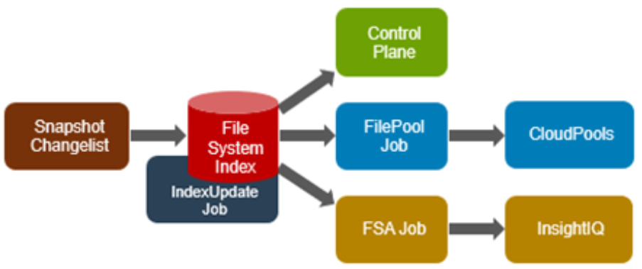
Avoiding a full treewalk dramatically decreases the amount of locking and metadata scanning work the job is required to perform, reducing impact on CPU and disk – albeit at the expense of not doing everything that SmartPools does. The FilePolicy job enforces just the SmartPools file pool policies, as opposed to the storage pool settings. For example, FilePolicy does not deal with changes to storage pools or storage pool settings, such as:
- Restriping activity due to adding, removing, or reorganizing node pools
- Changes to storage pool settings or defaults, including protection
However, the majority of the time SmartPools and FilePolicy perform the same work. Disabled by default, FilePolicy supports the full range of file pool policy features, reports the same information, and provides the same configuration options as the SmartPools job. Because FilePolicy is a changelist-based job, it performs best when run frequently – once or multiple times a day, depending on the configured file pool policies, data size, and rate of change.
Job schedules can easily be configured from the OneFS WebUI by navigating to Cluster Management > Job Operations, highlighting the desired job, and selecting ‘View\Edit’. The following example illustrates configuring the IndexUpdate job to run every six hours at a LOW impact level with a priority value of 5:
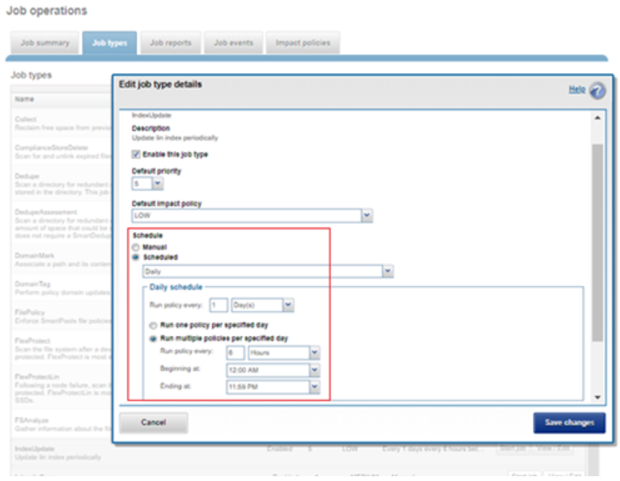
When enabling and using the FilePolicy and IndexUpdate jobs, the recommendation is to continue running the SmartPools job as well, but at a reduced frequency (monthly).
In addition to running on a configured schedule, the FilePolicy job can also be executed manually.
FilePolicy requires access to a current index. If the IndexUpdate job has not yet been run, attempting to start the FilePolicy job will fail with the error shown in the following figure. Instructions in the error message are displayed, prompting to run the IndexUpdate job first. When the index has been created, the FilePolicy job will run successfully. The IndexUpdate job can be run several times daily (that is, every six hours) to keep the index current and prevent the snapshots from getting large.
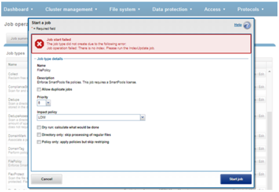
Consider using the FilePolicy job with the job schedule shown in the table below for workflows and datasets that have these characteristics:
- Data with long retention times
- Large number of small files
- Path-based File Pool filters configured
- Where FSAnalyze job is already running on the cluster (InsightIQ monitored clusters)
- There is already a SnapshotIQ schedule configured
- When the SmartPools job typically takes a day or more to run to completion at LOW impact
For clusters without these characteristics, the recommendation is to continue running the SmartPools job as usual and not to activate the FilePolicy job.
The following table provides a suggested job schedule when deploying FilePolicy:
Job | Schedule | Impact | Priority |
FilePolicy | Every day at 22:00 | LOW | 6 |
IndexUpdate | Every six hours, every day | LOW | 5 |
SmartPools | Monthly – Sunday at 23:00 | LOW | 6 |
Because no two clusters are the same, this suggested job schedule may require additional tuning to meet the needs of a specific environment.
Note that when clusters running older OneFS versions and the FSAnalyze job are upgraded to OneFS 8.2.x or later, the legacy FSAnalyze index and snapshots are removed and replaced by new snapshots the first time that IndexUpdate is run. The new index stores considerably more file and snapshot attributes than the old FSA index. Until the IndexUpdate job effects this change, FSA keeps running on the old index and snapshots.
Author: Nick Trimbee

A Metadata-based Approach to Tiering in PowerScale OneFS
Wed, 24 Apr 2024 13:12:26 -0000
|Read Time: 0 minutes
OneFS SmartPools provides sophisticated tiering between storage node types. Rules based on file attributes such as last accessed time or creation date can be configured in OneFS to drive transparent motion of data between PowerScale node types. This kind of “set and forget” approach to data tiering is ideal for some industries but not workable for most content creation workflows.
A classic case of how this kind of tiering falls short for media is the real-time nature of video playback. For an extreme example, take an uncompressed 4K image sequence (or even 8K), that might require >1.5GB/s of throughput to play properly. If this media has been tiered down to low performing archive storage and it needs to be used, those files must be migrated back up before they will play. This problem causes delays and confusion all around and makes media storage administrators hesitant to archive anything.
The good news is that the PowerScale OneFS ecosystem has a better way of doing things!
The approach I have taken here is to pull metadata from elsewhere in the workflow and use it to drive on demand tiering in OneFS. How does that work? OneFS supports file extended attributes, which are <key/value> pairs (metadata!) that can be written to the files and directories stored in OneFS. File Policies can be configured in OneFS to move data based on those file extended attributes. And a SmartPoolsTree job can be run on only the path that needs to be moved. All this goodness can be controlled externally by combining the DataIQ API and the OneFS API.
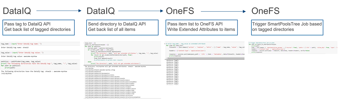
Figure 1: API flow
Note that while I’m focused on combining the DataIQ and OneFS APIs in this post, other API driven tools with OneFS file system visibility could be substituted for DataIQ.
DataIQ
DataIQ is a data indexing and analysis tool. It runs as an external virtual machine and maintains an index of mounted file systems. DataIQ’s file system crawler is efficient, fast, and lightweight, meaning it can be kept up to date with little impact on the storage devices it is indexing.
DataIQ has a concept called “tagging”. Tags in DataIQ apply to directories and provide a mechanism for reporting sets of related data. A tag in DataIQ is an arbitrary <key>/<value> pair. Directories can be tagged in DataIQ in three different ways:
- Autotagging rules:
- Tags are automatically placed in the file system based on regular expressions defined in the Autotagging configuration menu.
- Use of .cntag files:
- Empty files named in the format <key>.<value>.cntag are placed in directories and will be recognized as tags by DataIQ.
- API-based tagging:
- The DataIQ API allows for external tagging of directories.
Tags can be placed throughout a file system and then reported on as a group. For instance, temporary render directories could contain a render.temp.cntag file. Similarly, an external tool could access the DataIQ API and place a <Project/Name> tag on the top-level directory of each project. DataIQ can generate reports on the storage capacity those tags are consuming.
File system extended attributes in OneFS
As I mentioned earlier, OneFS supports file extended attributes. Extended attributes are arbitrary metadata tags in the form of <key/value> pairs that can be applied to files and directories. Extended attributes are not visible in the graphical interface or when accessing files over a share or export. However, the attributes can be accessed using the OneFS CLI with the getexattr and setextattr commands.
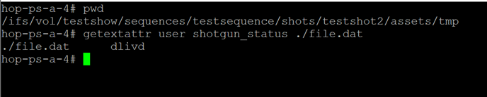
Figure 2: File extended attributes
The SmartPools job engine will move data between node pools based on these file attributes. And it is that SmartPools functionality that uses this metadata to perform on demand data tiering.
Crucially, OneFS supports creation of file system extended attributes from an external script using the OneFS REST API. The OneFS API Reference Guide has great information about setting and reading back file system extended attributes.
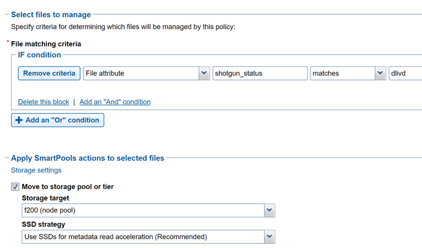
Figure 3: File policy configuration
Tiering example with Autodesk Shotgrid, DataIQ, and OneFS
Autodesk ShotGrid (formerly Shotgun) is a production resource management tool common in the visual effects and animation industries. ShotGrid is a cloud-based tool that allows for coordination of large production teams. Although it isn’t a storage management tool, its business logic can be useful in deciding what tier of storage a particular set of files should live on. For instance, if a shot tracked in ShotGrid is complete and delivered, the files associated with that shot could be moved to archive.
DataIQ plug-in for Autodesk ShotGrid
The open-source DataIQ plug-in for ShotGrid is available on GitHub here:
Dell DataIQ Autodesk ShotGrid Plugin
This plug-in is proof of concept code to show how the ShotGrid and DataIQ APIs can be combined to tag data in DataIQ based on shot status in ShotGrid. The DataIQ tags are dynamically updated with the current shot status in ShotGrid.
Here is a “shot” in ShotGrid configured with various possible statuses:
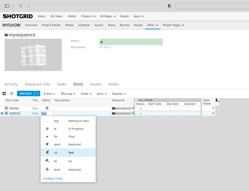
Figure 4: ShotGrid status
The following figure of DataIQ shows where the shot status field from ShotGrid has been automatically applied as a tag in DataIQ.
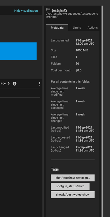
Figure 5: DataIQ tags
Once metadata from ShotGrid has been pulled into DataIQ, that information can be used to drive OneFS SmartPools tiering:
- A user (or system) passes the DataIQ tag <key/values> to the DataIQ API. The DataIQ API returns a list of directories associated with that tag.
- A directory chosen from Step 1 above can be passed back to the DataIQ API to get a listing of all contents by way of the DataIQ file index.
- Those items are passed programmatically to the OneFS API. The <key/value> pair of the original DataIQ tag is written as an extended attribute directly to the targeted files and directories.
- And finally, the SmartPoolsTree job can be run on the parent path chosen in Step 2 above to begin tiering the data immediately.
Using business logic to drive storage tiering
DataIQ and OneFS provide the APIs necessary to drive storage tiering based on business logic. Striking efficiencies can be gained by taking advantage of the metadata that exists in many workflow tools. It is a matter of “connecting the dots”.
The example in this blog uses ShotGrid and DataIQ, however it is easy to imagine that similar metadata-based techniques could be developed using other file system index tools. In the media and entertainment ecosystem, media asset management and production asset management systems immediately come to mind as candidates for this kind of API level integration.
As data volumes increase exponentially, it is unrealistic to keep all files on the highest costing tiers of storage. Various automated storage tiering approaches have been around for years, but for many use cases this automated tiering approach falls short. Bringing together rich metadata and an API driven workflow bridges the gap.
To see the Python required to put this process together, refer to my white paper PowerScale OneFS: A Metadata Driven Approach to On Demand Tiering.
Author: Gregory Shiff, Principal Solutions Architect, Media & Entertainment LinkedIn

Understanding the Protocol Syslog Format in PowerScale OneFS
Wed, 23 Feb 2022 19:23:07 -0000
|Read Time: 0 minutes
Recently I’ve received several queries on the format of the audit protocol syslog in PowerScale. It is a little bit complicated for the following reasons:
- For different protocol operations (such as OPEN and CLOSE), various fields have been defined to meet auditing goals.
- Some fields are easy to parse and some are more difficult.
- It is not currently documented.
Syslog format
The following table shows the details of the format of the syslog protocol in PowerScale. (This table is very wide. Extend your browser to show all 13 fields.):
Operation | Field 1 | Field 2 | Field 3 | Field 4 | Field 5 | Field 6 | Field 7 | Field 8 | Field 9 | Field 10 | Field 11 | Field 12 | Field 13 |
LOGON | userSID | zoneName | ZoneID | clientIPAddr | protocol | operation | ntStatus | username |
|
|
|
|
|
LOGOFF | userSID | zoneName | ZoneID | clientIPAddr | protocol | operation | ntStatus | username |
|
|
|
|
|
TREE-CONNECT | userSID | zoneName | ZoneID | clientIPAddr | protocol | operation | ntStatus |
|
|
|
|
|
|
READ | userSID | userID | zoneName | ZoneID | clientIPAddr | protocol | operation | ntStatus | isDirectory | inode/lin | filename |
|
|
WRITE | userSID | userID | zoneName | ZoneID | clientIPAddr | protocol | operation | ntStatus | isDirectory | inode/lin | filename |
|
|
CLOSE | userSID | userID | zoneName | ZoneID | clientIPAddr | protocol | operation | ntStatus | isDirectory | bytesRead | bytesWrite | inode/lin | filename |
DELETE | userSID | userID | zoneName | ZoneID | clientIPAddr | protocol | operation | ntStatus | isDirectory | inode/lin | filename |
|
|
GET_SECURITY | userSID | userID | zoneName | ZoneID | clientIPAddr | protocol | operation | ntStatus | isDirectory | inode/lin | filename |
|
|
SET_SECURITY | userSID | userID | zoneName | ZoneID | clientIPAddr | protocol | operation | ntStatus | isDirectory | inode/lin | filename |
|
|
OPEN | userSID | userID | zoneName | ZoneID | clientIPAddr | protocol | operation | ntStatus | desiredAccess | isDirectory | createResult | inode/lin | filename |
RENAME | userSID | userID | zoneName | ZoneID | clientIPAddr | protocol | operation | ntStatus | isDirectory | inode/lin | filename | newFileName |
|
Some Notes:
- Starting with OneFS 9.2.0.0, we apply the RFC 5425 as the standard of the syslog protocol.
- userSID: UserSID is a unique identifier for an object in Active Directory or NT4 domains. On a native Windows file server (as well as some other CIFS server implementations), this SID is used directly to determine a user's identity, and is generally stored on every file or folder in the file system that the user has rights to. SIDs commonly start with the letter `S', and include a series of numbers and dashes.
- userID: On most UNIX based systems, file and folder permissions are assigned to UIDs and GIDs (most commonly found in /etc/passwd and /etc/group).
- protocol: it’s one of the following:
- SMB
- NFS
- HDFS
SMB is also returned for the LOGON, LOGOFF, and TREE-CONNECT operations.
5. ntStatus:
- If the ntStatus field is 0, it will return “SUCCESS”.
- If the ntStatus field is non-zero, it will return “FAILD: <NT Status Code>”.
- If the ntStatus field is not in the payload, it will return “ERROR”.
- You can refer to the Microsoft Open Specifications (https://docs.microsoft.com/en-us/openspecs/windows_protocols/ms-erref/596a1078-e883-4972-9bbc-49e60bebca55) for the value and description of the NT Status Code.
6. isDirectory:
- If it’s a file, it will return “FILE”.
- If it’s a directory, it will return “DIR”.
Example

Conclusion
I hope you have found this helpful.
Thanks for reading!
Author: Vincent Shen

OneFS and Long Filenames
Fri, 28 Jan 2022 21:24:39 -0000
|Read Time: 0 minutes
Another feature debut in OneFS 9.3 is support for long filenames. Until now, the OneFS filename limit has been capped at 255 bytes. However, depending on the encoding type, this could potentially be an impediment for certain languages such as Chinese, Hebrew, Japanese, Korean, and Thai, and can create issues for customers who work with international languages that use multi-byte UTF-8 characters.
Since some international languages use up to 4 bytes per character, a file name of 255 bytes could be limited to as few as 63 characters when using certain languages on a cluster.
To address this, the new long filenames feature provides support for names up to 255 Unicode characters, by increasing the maximum file name length from 255 bytes to 1024 bytes. In conjunction with this, the OneFS maximum path length is also increased from 1024 bytes to 4096 bytes.
Before creating a name length configuration, the cluster must be running OneFS 9.3. However, the long filename feature is not activated or enabled by default. You have to opt-in by creating a “name length” configuration. That said, the recommendation is to only enable long filename support if you are actually planning on using it. This is because, once enabled, OneFS does not track if, when, or where, a long file name or path is created.
The following procedure can be used to configure a PowerScale cluster for long filename support:
Step 1: Ensure cluster is running OneFS 9.3 or later
The ‘uname’ CLI command output will display a cluster’s current OneFS version.
For example:
# uname -sr Isilon OneFS v9.3.0.0
The current OneFS version information is also displayed at the upper right of any of the OneFS WebUI pages. If the output from Step 1 shows the cluster running an earlier release, an upgrade to OneFS 9.3 will be required. This can be accomplished either using the ‘isi upgrade cluster’ CLI command or from the OneFS WebUI, by going to Cluster Management > upgrade.
Once the upgrade has completed it will need to be committed, either by following the WebUI prompts, or using the ‘isi upgrade cluster commit’ CLI command.
Step 2. Verify cluster’s long filename support configuration: Viewing a cluster’s long filename support settings
The ‘isi namelength list’ CLI command output will verify a cluster’s long filename support status. For example, the following cluster already has long filename support enabled on the /ifs/tst path:
# isi namelength list Path Policy Max Bytes Max Chars ----------------------------------------- /ifs/tst restricted 255 255 ----------------------------------------- Total: 1
Step 3. Configure long filename support
The ‘isi namelength create <path>’ CLI command can be run on the cluster to enable long filename support.
# mkdir /ifs/lfn # isi namelength create --max-bytes 1024 --max-chars 1024 /ifs/lfn
By default, namelength support is created with default maximum values of 255 bytes in length and 255 characters.
Step 4: Confirm long filename support is configured
The ‘isi namelength list’ CLI command output will confirm that the cluster’s /ifs/lfn directory path is now configured to support long filenames:
# isi namelength list Path Policy Max Bytes Max Chars ----------------------------------------- /ifs/lfn custom 1024 1024 /ifs/tst restricted 255 255 ----------------------------------------- Total: 2
Name length configuration is set up per directory and can be nested. Plus, cluster-wide configuration can be applied by configuring at the root /ifs level.
Filename length configurations have two defaults:
- “Full” – which is 1024 bytes, 255 characters.
- “Restricted” – which is 255 bytes, 255 characters, and the default if no long additional filename configuration is specified.
Note that removing the long name configuration for a directory will not affect its contents, including any previously created files and directories with long names. However, it will prevent any new long-named files or subdirectories from being created under that directory.
If a filename is too long for a particular protocol, OneFS will automatically truncate the name to around 249 bytes with a ‘hash’ appended to it, which can be used to consistently identify and access the file. This shortening process is referred to as ‘name mangling’. If, for example, a filename longer than 255 bytes is returned in a directory listing over NFSv3, the file’s mangled name will be presented. Any subsequent lookups of this mangled name will resolve to the same file with the original long name. Be aware that filename extensions will be lost when a name is mangled, which can have ramifications for Windows applications, and so on.
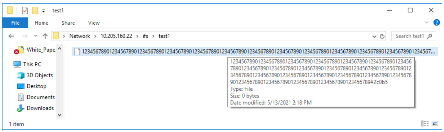
If long filename support is enabled on a cluster with active SyncIQ policies, all source and target clusters must have OneFS 9.3 or later installed and committed, and long filename support enabled.
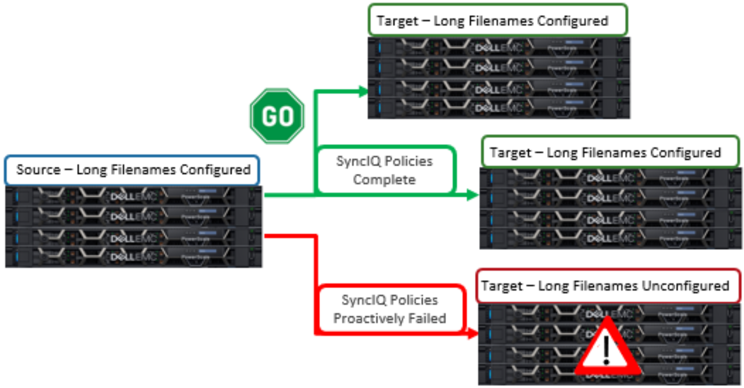
However, the long name configuration does not need to be identical between the source and target clusters -- it only needs to be enabled. This can be done via the following sysctl command:
# sysctl efs.bam.long_file_name_enabled=1
When the target cluster for a Sync policy does not support long file names for a SyncIQ policy and the source domain has long file names enabled, the replication job will fail. The subsequent SyncIQ job report will include the following error message: 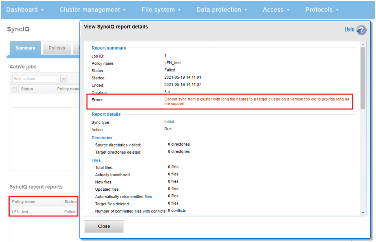
Note that the OneFS checks are unable to identify a cascaded replication target running an earlier OneFS version and/or without long filenames configured.
So there are a couple of things to bear in mind when using long filenames:
- Restoring data from a 9.3 NDMP backup containing long filenames to a cluster running an earlier OneFS version will fail with an ‘ENAMETOOLONG’ error for each long-named file. However, all the files with regular length names will be successfully restored from the backup stream.
- OneFS ICAP does not support long filenames. However CAVA, ICAP’s replacement, is compatible.
- The ‘isi_vol_copy’ migration utility does not support long filenames.
- Neither does the OneFS WebDAV protocol implementation.
- Symbolic links created via SMB are limited to 1024 bytes due to the size limit on extended attributes.
- Any pathnames specified in long filename pAPI operations are limited to 4068 bytes.
- And finally, while an increase in long named files and directories could potentially reduce the number of names the OneFS metadata structures can hold, the overall performance impact of creating files with longer names is negligible.
Author: Nick Trimbee

OneFS Virtual Hot Spare
Fri, 28 Jan 2022 21:12:37 -0000
|Read Time: 0 minutes
There have been several recent questions from the field around how a cluster manages space reservation and pre-allocation of capacity for data repair and drive rebuilds.
OneFS provides a mechanism called Virtual Hot Spare (VHS), which helps ensure that node pools maintain enough free space to successfully re-protect data in the event of drive failure.
Although globally configured, Virtual Hot Spare actually operates at the node pool level so that nodes with different size drives reserve the appropriate VHS space. This helps ensure that, while data may move from one disk pool to another during repair, it remains on the same class of storage. VHS reservations are cluster wide and configurable as either a percentage of total storage (0-20%) or as a number of virtual drives (1-4). To achieve this, the reservation mechanism allocates a fraction of the node pool’s VHS space in each of its constituent disk pools.
No space is reserved for VHS on SSDs unless the entire node pool consists of SSDs. This means that a failed SSD may have data moved to HDDs during repair, but without adding additional configuration settings. This avoids reserving an unreasonable percentage of the SSD space in a node pool.
The default for new clusters is for Virtual Hot Spare to have both “subtract the space reserved for the virtual hot spare…” and “deny new data writes…” enabled with one virtual drive. On upgrade, existing settings are maintained.
It is strongly encouraged to keep Virtual Hot Spare enabled on a cluster, and a best practice is to configure 10% of total storage for VHS. If VHS is disabled and you upgrade OneFS, VHS will remain disabled. If VHS is disabled on your cluster, first check to ensure the cluster has sufficient free space to safely enable VHS, and then enable it.
VHS can be configured via the OneFS WebUI, and is always available, regardless of whether SmartPools has been licensed on a cluster. For example:
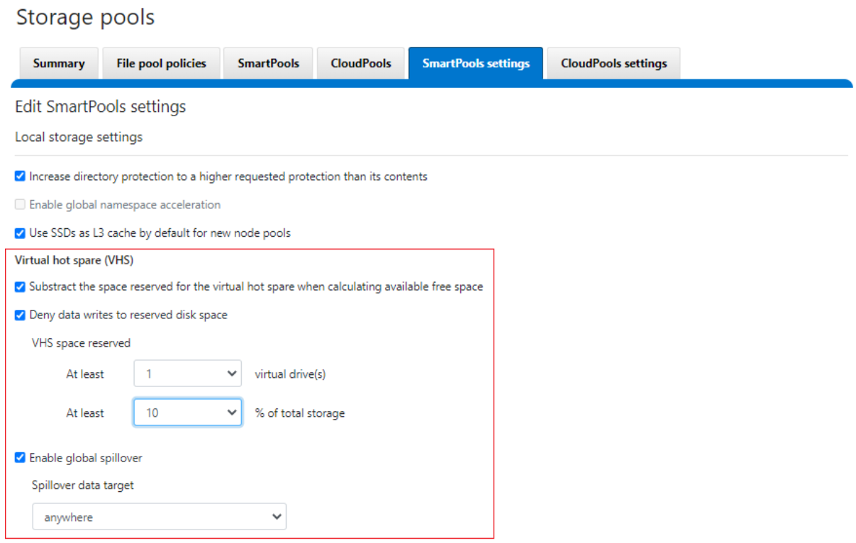
From the CLI, the cluster’s VHS configuration is part of the storage pool settings, and can be viewed with the following syntax:
# isi storagepool settings view Automatically Manage Protection: files_at_default Automatically Manage Io Optimization: files_at_default Protect Directories One Level Higher: Yes Global Namespace Acceleration: disabled Virtual Hot Spare Deny Writes: Yes Virtual Hot Spare Hide Spare: Yes Virtual Hot Spare Limit Drives: 1 Virtual Hot Spare Limit Percent: 10 Global Spillover Target: anywhere Spillover Enabled: Yes SSD L3 Cache Default Enabled: Yes SSD Qab Mirrors: one SSD System Btree Mirrors: one SSD System Delta Mirrors: one
Similarly, the following command will set the cluster’s VHS space reservation to 10%.
# isi storagepool settings modify --virtual-hot-spare-limit-percent 10
Bear in mind that reservations for virtual hot sparing will affect spillover. For example, if VHS is configured to reserve 10% of a pool’s capacity, spillover will occur at 90% full.
Spillover allows data that is being sent to a full pool to be diverted to an alternate pool. Spillover is enabled by default on clusters that have more than one pool. If you have a SmartPools license on the cluster, you can disable Spillover. However, it is recommended that you keep Spillover enabled. If a pool is full and Spillover is disabled, you might get a “no space available” error but still have a large amount of space left on the cluster.
If the cluster is inadvertently configured to allow data writes to the reserved VHS space, the following informational warning will be displayed in the SmartPools WebUI:
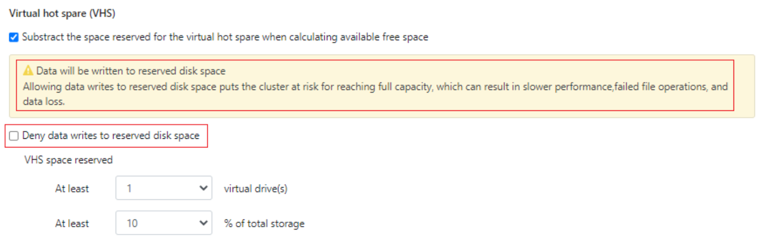
There is also no requirement for reserved space for snapshots in OneFS. Snapshots can use as much or little of the available file system space as desirable and necessary.
A snapshot reserve can be configured if preferred, although this will be an accounting reservation rather than a hard limit and is not a recommend best practice. If desired, snapshot reserve can be set via the OneFS command line interface (CLI) by running the ‘isi snapshot settings modify –reserve’ command.
For example, the following command will set the snapshot reserve to 10%:
# isi snapshot settings modify --reserve 10
It’s worth noting that the snapshot reserve does not constrain the amount of space that snapshots can use on the cluster. Snapshots can consume a greater percentage of storage capacity specified by the snapshot reserve.
Additionally, when using SmartPools, snapshots can be stored on a different node pool or tier than the one the original data resides on.
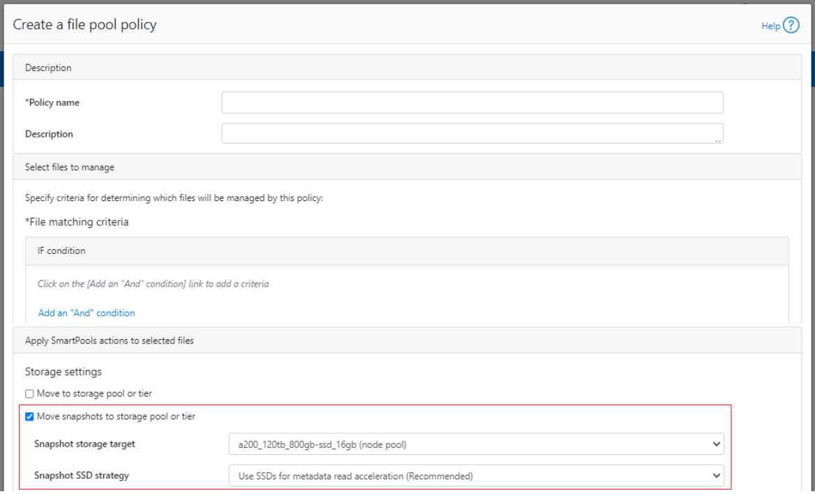
For example, as above, the snapshots taken on a performance aligned tier can be physically housed on a more cost effective archive tier.
Author: Nick Trimbee

Configure SSH Multi-Factor Authentication on OneFS Using Duo
Thu, 27 Jan 2022 21:03:07 -0000
|Read Time: 0 minutes
Duo Security at Cisco is a vendor of cloud-based multi-factor authentication (MFA) services. MFA enables security to prevent a hacker from masquerading as an authenticated user. Duo allows an administrator to require multiple options for secondary authentication. With multi-factor authentication, even though a hacker steals the username and password, he cannot be authenticated to a network service easily without a user’s device.
SSH Multi-Factor Authentication (MFA) with Duo is a new feature introduced in OneFS 8.2. Currently, OneFS supports the SSH MFA with Duo service through SMS (short message service), phone callback, and Push notification via the Duo app. This blog describes how to integrate OneFS SSH MFA with the Duo service.
Duo supports many kinds of applications, such as Microsoft Azure Active Directory, Cisco Webex, and Amazon Web Services. For a OneFS cluster, it appears as a "Unix Application" entry. To integrate OneFS with the Duo service, you must configure the Duo service and the OneFS cluster. Before configuring OneFS with Duo, you need to have Duo account. In this blog, we used a trial version account for demonstration purposes.
Failback mode
By default, the SSH failback mode for Duo in OneFS is “safe”, which allows common authentication if the Duo service is not available. The “secure” mode will deny SSH access if the Duo service is not available, including the bypass users, because the bypass users are defined and validated in the Duo service. To configure the failback mode in OneFS, specify the --failmode option using the following command:
# isi auth duo modify --failmode
Exclusion group
By default, all groups are required to use Duo unless the group is configured to bypass Duo auth. The groups option allows you to exclude or specify dedicated user groups from using Duo service authentication. This method provides a way to configure users so they can still SSH into the cluster even when the Duo service is not available and failback mode is set to “secure”. Otherwise, all users may be locked out of the cluster in this situation.
To configure the exclusion group option, add an exclamation character “!” before the group name and preceded by an asterisk to ensure that all other groups use Duo service. For example:
# isi auth duo modify --groups=”*,!groupname”
Note: zsh shell requires the “!” to be escaped. In this case, the example above should be changed to:
# isi auth duo modify --groups=”*,\!groupname”
Prepare the Duo service for OneFS
1. Use your new Duo account to log into the Duo Admin Panel. Select the Application item from the left menu, then click Protect an Application, as shown in Figure 1.

Figure 1 Protect an Application
2. Type “Unix Application” in the search bar. Click Protect this Application to create a new UNIX Application entry.

Figure 2 Search for UNIX Application
3. Scroll down the creation page to find the Settings section. Type a name for the new UNIX Application. Try to use a name that can recognize your OneFS cluster, as shown in Figure 3. In the Settings section, you can also find the Duo’s name normalization setting.
By default, Duo username normalization is not AD aware. This means that it will alter incoming usernames before trying to match them to a user account. For example, "DOMAIN\username", "username@domain.com", and "username" are treated as the same user. For other options, refer to here.

Figure 3 UNIX Application Name
4. Check the required information for OneFS under the Details section, including API hostname, integration key, and secret key, as shown in Figure 4.

Figure 4 Required Information for OneFS
5. Manually enroll a user. In this example, we are creating a user named admin, which is the default OneFS administrator user. Switch the menu item to Users and click the Add User button, as shown in Figure 5. For details about user enrollment in the Duo service, refer to the Duo documentation Enrolling Users.

Figure 5 User Enrollment
6. Type the user name, as shown in Figure 6.

Figure 6 Manually User Enrollment
7. Find the Phones settings in the user page and click the Add Phone button to add a device for the user. See Figure 7.

Figure 7 Add Phone for User
8. Type your phone number.

Figure 8 Add New Phone
9. (optional) If you want to use Duo push authentication methods, you need to install the Duo Mobile app in the phone and activate the Duo Mobile app. As highlighted in Figure 9, click the link to activate the Duo Mobile app.

Figure 9 Activate the Duo Mobile app
The Duo service is now prepared for OneFS. Now let's go on to configure OneFS.
Configuring and verifying OneFS
1. By default, the authentication setting template is set for “any”. To use OneFS with the Duo service, the authentication setting template must not be set to “any” or “custom”. It should be set to “password”, “publickey”, or “both”. In the following example, we are configuring the setting to “password”, which will use user password and Duo for SSH MFA.
# isi ssh modify --auth-settings-template=password
2. To confirm the authentication method, use the following command:
# isi ssh settings view| grep "Auth Settings Template"
Auth Settings Template: password
3. Configure the required Duo service information and enable it for SSH MFA, as shown here. Use the same information as when we set up the UNIX Application in Duo, including API hostname, integration key, and secret key.
# isi auth duo modify --enabled=true --failmode=safe --host=api-13b1ee8c.duosecurity.com --ikey=DIRHW4IRSC7Q4R1YQ3CQ --set-skey Enter skey: Confirm:
4. Verify SSH MFA using the user “admin”. An SMS passcode and the user’s password are used for authentication in this example, as shown in Figure 10.

Figure 10 SSH MFA Verification
You have now completed the configuration on your Duo service portal and OneFS cluster as well! SSH users have to be authenticated with Duo, therefore, you can further strengthen your OneFS cluster security with MFA enabled.
Author: Lieven Lin

Introducing the Accelerator Nodes – the Latest Additions to the Dell PowerScale Family
Thu, 20 Jan 2022 14:45:39 -0000
|Read Time: 0 minutes
The Dell PowerScale family announced a recent addition with the latest release of accelerator nodes. Accelerator nodes contribute additional CPU, memory, and network bandwidth to a cluster that already has adequate storage resources.
The PowerScale accelerator nodes include the PowerScale P100 performance accelerator and the PowerScale B100 backup accelerator. Both the P100 and B100 are based on 1U PowerEdge R640 servers and can be part of a PowerScale cluster that is powered by OneFS 9.3 or later. The accelerator nodes contain boot media only and are optimized for CPU/memory configurations. A single P100 or B100 node can be added to a cluster. Expansion is through single node increments.
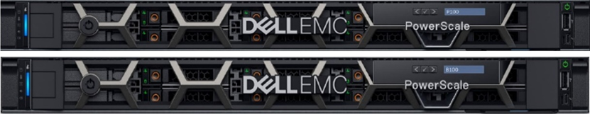
PowerScale all-flash and all-NVMe storage deliver the necessary performance to meet demanding workloads. If additional capabilities are required, new nodes can be non-disruptively added to the cluster, to provide both performance and capacity. There may be specialized compute-bound workloads that require extra performance but don’t need any additional capacity. These types of workloads may benefit by adding the PowerScale P100 performance accelerator node to the cluster. The accelerator node contributes CPU, memory, and network bandwidth capabilities to the cluster. This accelerated storage solution delivers incremental performance at a lower cost. Let’s look at each in detail.
A PowerScale P100 Performance Accelerator node adds performance to the workflows on a PowerScale cluster that is composed of CPU-bound nodes. The P100 provides a dedicated cache, separate from the cluster. Adding CPU to the cluster will improve performance where there are read/re-read intensive workloads. The P100 also provides additional network bandwidth to a cluster through the additional front-end ports.
With rapid data growth, organizations are challenged by shrinking backup windows that impact business productivity and the ability to meet IT requirements for tape backup, and compliance archiving. In such an environment, providing fast, efficient, and reliable data protection is essential. Given the 24x7 nature of the business, a high-performance backup solution delivers the performance and scale to address the SLAs of the business. Adding one or more PowerScale B100 backup accelerator nodes to a PowerScale cluster can reduce risk while addressing backup protection needs.
A PowerScale B100 Backup Accelerator enables backing up a PowerScale cluster using a two-way NDMP protocol. The B100 is delivered in a cost-effective form factor to address the SLA targets and tape backup needs of a wide variety of workloads. Each node includes Fibre Channel ports that can connect directly to a tape subsystem or a Storage Area Network (SAN). The B100 can benefit backup operations as it reduces overhead on the cluster, by going through the Fibre Channel ports directly, thereby separating front-end and NDMP traffic.
The PowerScale P100 and B100 nodes can be monitored using the same tools available today, including the OneFS web administration interface, the OneFS command-line interface, Dell DataIQ, and InsightIQ.
In a world where unstructured data is growing rapidly and taking over the data center, organizations need an enterprise storage solution that provides the flexibility to address the additional performance needs of certain workloads, and that meets the organization’s overall data protection requirements.
The following information provides the technical specifications and best practice design considerations of the PowerScale Accelerator nodes:
- PowerScale Accelerator Nodes Specification Sheet
- PowerScale: NDMP Technical Overview and Design Considerations
- PowerScale: Accelerator Nodes Overview and General Best Practices
Author: Cris Banson

OneFS & Files Per Directory
Thu, 13 Jan 2022 15:00:46 -0000
|Read Time: 0 minutes
Had several recent inquiries from the field recently asking about the low impact methods to count the number of files in large directories containing hundreds of thousands to millions of files).
Unfortunately, there’s no ‘silver bullet’ command or data source available that will provide that count instantaneously: Something will have to perform a treewalk to gather these stats. That said, there are a couple of approaches to this, each with its pros and cons:
- If the customer has a SmartQuotas license, they can configure an advisory directory quota on the directories they want to check. As mentioned, the first job run will require working the directory tree, but they can get fast, low impact reports moving forward.
- Another approach is using traditional UNIX commands, either from the OneFS CLI or, less desirably, from a UNIX client. The two following commands will both take time to run: “
# ls -f /path/to/directory | wc –l # find /path/to/directory -type f | wc -l
It’s worth noting that when counting files with ls, you’ll probably get faster results by omitting the ‘-l’ flag and using ‘-f’ flag instead. This is because ‘-l’ resolves UID & GIDs to display users/groups, which creates more work thereby slowing the listing. In contrast, ‘-f’ allows the ‘ls’ command to avoid sorting the output. This should be faster and reduce memory consumption when listing extremely large numbers of files.
Ultimately, there really is no quick way to walk a file system and count the files – especially since both ls and find are single threaded commands. Running either of these in the background with output redirected to a file is probably the best approach.
Depending on your arguments for the ls or find command, you can gather a comprehensive set of context info and metadata on a single pass.
# find /path/to/scan -ls > output.file
It will take quite a while for the command to complete, but once you have the output stashed in a file you can pull all sorts of useful data from it.
Assuming a latency of 10ms per file it would take 33 minutes for 200,000 files. While this estimate may be conservative, there are typically multiple protocol ops that need to be done to each file, and they do add up. Plus, as mentioned before, ‘ls’ is a single threaded command.
- If possible, ensure the directories of interest are stored on a file pool that has at least one of the metadata mirrors on SSD (metadata-read).
- Windows Explorer can also enumerate the files in a directory tree surprisingly quickly. All you get is a file count, but it can work pretty well.
- If the directory you wish to know the file count for just happens to be /ifs, you can run the LinCount job, which will tell you how many LINs there are in the file system.
Lincount (relatively) quickly scans the filesystem and returns the total count of LINs (logical inodes). The LIN count is essentially equivalent to the total file and directory count on a cluster. The job itself runs by default at the LOW priority and is the fastest method of determining object count on OneFS, assuming no other job has run to completion.
The following syntax can be used to kick off the Lincount job from the OneFS CLI:
# isi job start lincount
The output from this will be along the lines of “Added job [52]”.
Note: The number in square brackets is the job ID.
To view results, run the following command from the CLI:
# isi job reports view [job ID]
For example:
# isi job reports view 52 LinCount[52] phase 1 (2021-07-06T09:33:33) ------------------------------------------ Elapsed time 1 seconds Errors 0 Job mode LinCount LINs traversed 1722 SINs traversed 0
The "LINs traversed" metric indicates that 1722 files and directories were found.
Note: The Lincount job will also include snapshot revisions of LINs in its count.
Alternatively, if another treewalk job has run against the directory you wish to know the count for, you might be in luck.
At any rate, hundreds of thousands of files is a large number to store in one directory. To reduce the directory enumeration time, where possible divide the files up into multiple subdirectories.
When it comes to NFS, the behavior is going to partially depend on whether the client is doing READDIRPLUS operations vs READDIR. READDIRPLUS is useful if the client is going to need the metadata. However, ff all you’re trying to do is list the filenames, it actually makes that operation much slower.
If you only read the filenames in the directory, and you don’t attempt to stat any associated metadata, then this requires a relatively small amount of I/O to pull the names from the meta-tree and should be fairly fast.
If this has already been done recently, some or all of the blocks are likely to already be in L2 cache. As such, a subsequent operation won’t need to read from hard disk and will be substantially faster.
NFS is more complicated regarding what it will and won’t cache on the client side, particularly with the attribute cache and the timeouts that are associated with it.
Here are some options from fastest to slowest:
- If NFS is using READDIR, as opposed to READDIRPLUS, and the ‘ls’ command is invoked with the appropriate arguments to prevent it polling metadata or sorting the output, execution will be relatively swift.
- If ‘ls’ polls the metadata (or if NFS uses READDIRPLUS) but doesn’t sort the results, output will be fairly immediately, but will take longer to complete overall.
- If ‘ls’ sorts the output, nothing will be displayed until ls has read everything and sorted it, then you’ll get the output in a deluge at the end.
Author: Nick Trimbee

OneFS NFS Netgroups
Thu, 13 Jan 2022 15:17:23 -0000
|Read Time: 0 minutes
A OneFS network group, or netgroup, defines a network-wide group of hosts and users. As such, they can be used to restrict access to shared NFS filesystems, etc. Network groups are stored in a network information services, such as LDAP, NIS, or NIS+, rather than in a local file. Netgroups help to simplify the identification and management of people and machines for access control.
The isi_netgroup_d service provides netgroup lookups and caching for consumers of the ‘isi_nfs’ library. Only mountd and the ‘isi nfs’ command-line interface use this service. The isi_netgroup_d daemon maintains a fast, persistent cluster-coherent cache containing netgroups and netgroup members. isi_netgroup_d enforces netgroup TTLs and netgroup retries. A persistent cache database (SQLite) exists to store and recover cache data across reboots. Communication with isi_netgroup_d is via RPC and it will register its service and port with the local rpcbind.
Within OneFS, the netgroup cache possesses the following gconfig configuration parameters:
# isi_gconfig -t nfs-config | grep cache shared_config.bypass_netgroup_cache_daemon (bool) = false netcache_config.nc_ng_expiration (uint32) = 3600000 netcache_config.nc_ng_lifetime (uint32) = 604800 netcache_config.nc_ng_retry_wait (uint32) = 30000 netcache_config.ncdb_busy_timeout (uint32) = 900000 netcache_config.ncdb_write (uint32) = 43200000 netcache_config.nc_max_hosts (uint32) = 200000
Similarly, the following files are used by the isi_netgroup_d daemon:
File | Purpose |
/var/run/isi_netgroup_d.pid | The pid of the currently running isi_netgroup_d |
/ifs/.ifs/modules/nfs/nfs_config.gc | Server configuration file |
/ifs/.ifs/modules/nfs/netcache.db | Persistent cache database |
/var/log/isi_netgroup_d.log | Log output file |
In general, using IP addresses works better than hostnames for netgroups. This is because hostnames require a DNS lookup and resolution from FQDN to IP address. Using IP addresses directly saves this overhead.
Resolving a large set of hosts in the allow/deny list is significantly faster when using netgroups. Entering a large host list in the NFS export means OneFS has to look up the hosts for each individual NFS export. In Netgroups, once looked up, it is cached by netgroups, so it doesn’t have to be looked up again if there are overlap between exports. It is also better to use an LDAP (or NIS) server when using Netgroups instead of the flat file. If you have a large list of hosts in the netgroups file, it can take a while to resolve as it is single threaded and sequential. LDAP/NIS provider based netgroups lookup is parallelized.
The OneFS netgroup cache has a default limit in gconfig of 200,000 host entries.
# isi_gconfig -t nfs-config | grep max netcache_config.nc_max_hosts (uint32) = 200000
So, what is the waiting period between when /etc/netgroup is updated to when the NFS export realizes the change? OneFS uses a netgroup cache and both its expiration and lifetime are both tunable. The netgroup expiration and lifetime can be configured with this following CLI command:
# isi nfs netgroup modify --expiration or -e <duration> Set the netgroup expiration time. --lifetime or -l <duration> Set the netgroup lifetime.
OneFS also provides the ‘isi nfs netgroups flush’ CLI command, which can be used to force a reload of the file.
# isi nfs netgroup flush
[--host <string>]
[{--verbose | -v}]
[{--help | -h}]
Options:
--host <string>
IP address of the node to flush. Defaults is all nodes.
Display Options:
--verbose | -v
Display more detailed information.
--help | -h
Display help for this command.However, it is not recommended to flush the cache as a part of normal cluster operation. Refresh will walk the file and update the cache as needed.
Another area of caution is applying a netgroup with unresolved hostname(s). This will also slow down resolution of the hosts in the file when a refresh or startup of node happens. The best practice is to ensure that each host in the netgroups file is resolvable in DNS, or to just use IP addresses rather than names in the netgroup.
When it comes to switching to a netgroup for clients already on an export, a netgroup can be added and clients removed in one step (#1 –add-client netgroup –remove-clients 1,2,3 ,etc.). The cluster allows a mix of netgroup and host entries, so duplicates are tolerated. However, it’s worth noting that if there are unresolvable hosts in both areas, the startup resolution time will take that much longer.
Author: Nick Trimbee

OneFS Protocol Auditing
Thu, 13 Jan 2022 15:38:26 -0000
|Read Time: 0 minutes
Auditing can detect potential sources of data loss, fraud, inappropriate entitlements, access attempts that should not occur, and a range of other anomalies that are indicators of risk. This can be especially useful when the audit associates data access with specific user identities.
In the interests of data security, OneFS provides ‘chain of custody’ auditing by logging specific activity on the cluster. This includes OneFS configuration changes plus NFS, SMB, and HDFS client protocol activity, which are required for organizational IT security compliance, as mandated by regulatory bodies like HIPAA, SOX, FISMA, MPAA, etc.
OneFS auditing uses Dell EMC’s Common Event Enabler (CEE) to provide compatibility with external audit applications. A cluster can write audit events across up to five CEE servers per node in a parallel, load-balanced configuration. This allows OneFS to deliver an end to end, enterprise grade audit solution which efficiently integrates with third party solutions like Varonis DatAdvantage.
OneFS auditing provides control over exactly what protocol activity is audited. For example:
- Stops collection of unneeded audit events that 3rd party applications do not register for
- Reduces the number of audit events collected to only what is needed. Less unneeded events are stored on ifs and sent off cluster.
OneFS protocol auditing events are configurable at CEE granularity, with each OneFS event mapping directly to a CEE event. This allows customers to configure protocol auditing to collect only what their auditing application requests, reducing both the number of events discarded by CEE and stored on /ifs.
The ‘isi audit settings’ command syntax and corresponding platform API are used to specify the desired events for the audit filter to collect.
A ‘detail_type’ field within OneFS internal protocol audit events allows a direct mapping to CEE audit events. For example:
“protocol":"SMB2", "zoneID":1, "zoneName":"System", "eventType":"rename", "detailType":"rename-directory", "isDirectory":true, "clientIPAddr":"10.32.xxx.xxx", "fileName":"\\ifs\\test\\New folder", "newFileName":"\\ifs\\test\\ABC", "userSID":"S-1-22-1-0", "userID":0,
Old audit events are processed and mapped to the same CEE audit events as in previous releases. Backwards compatibility is maintained with previous audit events such that old versions ignore the new field. There are no changes to external audit events sent to CEE or syslog.
- New default audit events when creating an access zone
Here are the protocol audit events:
New OneFS Audit Event | Pre-8.2 Audit Event |
create_file | create |
create_directory | create |
open_file_write | create |
open_file_read | create |
open_file_noaccess | create |
open_directory | create |
close_file_unmodified | close |
close_file_modified | close |
close_directory | close |
delete_file | delete |
delete_directory | delete |
rename_file | rename |
rename_directory | rename |
set_security_file | set_security |
set_security_directory | set_security |
get_security_file, | get_security |
get_security_directory | get_security |
write_file | write |
read_file | read |
Audit Event |
logon |
logoff |
tree_connect |
The ‘isi audit settings’ CLI command syntax is a follows:
Usage: isi audit <subcommand> Subcommands: settings Manage settings related to audit configuration. topics Manage audit topics. logs Delete out of date audit logs manually & monitor process. progress Get the audit event time.
All options that take <events> use the protocol audit events:
# isi audit settings view –zone=<zone> # isi audit settings modify --audit-success=<events> --zone=<zone> # isi audit settings modify --audit-failure=<events> --zone=<zone> # isi audit settings modify --syslog-audit-events=<events> --zone=<zone>
When it comes to troubleshooting audit on a cluster, the ‘isi_audit_viewer’ utility can be used to list protocol audit events collected.
# isi_audit_viewer -h Usage: isi_audit_viewer [ -n <nodeid> | -t <topic> | -s <starttime>| -e <endtime> | -v ] -n <nodeid> : Specify node id to browse (default: local node) -t <topic> : Choose topic to browse. Topics are "config" and "protocol" (default: "config") -s <start> : Browse audit logs starting at <starttime> -e <end> : Browse audit logs ending at <endtime> -v verbose : Prints out start / end time range before printing records
The new audit event type is in the ‘detail_type’ field. Additionally, any errors that are encountered while processing audit events, and when delivering them to an external CEE server, are written to the log file ‘/var/log/isi_audit_cee.log’. Additionally, the protocol specific logs will contain any issues the audit filter has collecting while auditing events.
These protocol log files are:
Protocol | Log file |
HDFS | /var/log/hdfs.log |
NFS | /var/log/nfs.log |
SMB | /var/log/lwiod.log |
S3 | /var/log/s3.log |
Author: Nick Trimbee

OneFS Hardware Fault Tolerance
Thu, 13 Jan 2022 15:42:03 -0000
|Read Time: 0 minutes
There have been several inquiries recently around PowerScale clusters and hardware fault tolerance, above and beyond file level data protection via erasure coding. It seemed like a useful topic for a blog article, so here are some of the techniques which OneFS employs to help protect data against the threat of hardware errors:
File system journal
Every PowerScale node is equipped with a battery backed NVRAM file system journal. Each journal is used by OneFS as stable storage, and guards write transactions against sudden power loss or other catastrophic events. The journal protects the consistency of the file system and the battery charge lasts up to three days. Since each member node of a cluster contains an NVRAM controller, the entire OneFS file system is therefore fully journaled.
Proactive device failure
OneFS will proactively remove, or SmartFail, any drive that reaches a particular threshold of detected Error Correction Code (ECC) errors, and automatically reconstruct the data from that drive and locate it elsewhere on the cluster. Both SmartFail and the subsequent repair process are fully automated and hence require no administrator intervention.
Data integrity
ISI Data Integrity (IDI) is the OneFS process that protects file system structures against corruption via 32-bit CRC checksums. All OneFS blocks, both for file and metadata, utilize checksum verification. Metadata checksums are housed in the metadata blocks themselves, whereas file data checksums are stored as metadata, thereby providing referential integrity. All checksums are recomputed by the initiator, the node servicing a particular read, on every request.
In the event that the recomputed checksum does not match the stored checksum, OneFS will generate a system alert, log the event, retrieve and return the corresponding error correcting code (ECC) block to the client and attempt to repair the suspect data block.
Protocol checksums
In addition to blocks and metadata, OneFS also provides checksum verification for Remote Block Management (RBM) protocol data. As mentioned above, the RBM is a unicast, RPC-based protocol used over the back-end cluster interconnect. Checksums on the RBM protocol are in addition to the InfiniBand hardware checksums provided at the network layer and are used to detect and isolate machines with certain faulty hardware components and exhibiting other failure states.
Dynamic sector repair
OneFS includes a Dynamic Sector Repair (DSR) feature whereby bad disk sectors can be forced by the file system to be rewritten elsewhere. When OneFS fails to read a block during normal operation, DSR is invoked to reconstruct the missing data and write it to either a different location on the drive or to another drive on the node. This is done to ensure that subsequent reads of the block do not fail. DSR is fully automated and completely transparent to the end-user. Disk sector errors and Cyclic Redundancy Check (CRC) mismatches use almost the same mechanism as the drive rebuild process.
MediaScan
MediaScan’s role within OneFS is to check disk sectors and deploy the above DSR mechanism in order to force disk drives to fix any sector ECC errors they may encounter. Implemented as one of the phases of the OneFS job engine, MediaScan is run automatically based on a predefined schedule. Designed as a low-impact, background process, MediaScan is fully distributed and can thereby leverage the benefits of a cluster’s parallel architecture.
IntegrityScan
IntegrityScan, another component of the OneFS job engine, is responsible for examining the entire file system for inconsistencies. It does this by systematically reading every block and verifying its associated checksum. Unlike traditional ‘fsck’ style file system integrity checking tools, IntegrityScan is designed to run while the cluster is fully operational, thereby removing the need for any downtime. In the event that IntegrityScan detects a checksum mismatch, a system alert is generated and written to the syslog and OneFS automatically attempts to repair the suspect block.
The IntegrityScan phase is run manually if the integrity of the file system is ever in doubt. Although this process may take several days to complete, the file system is online and completely available during this time. Additionally, like all phases of the OneFS job engine, IntegrityScan can be prioritized, paused or stopped, depending on the impact to cluster operations and other jobs.
Fault isolation
Because OneFS protects its data at the file-level, any inconsistencies or data loss is isolated to the unavailable or failing device—the rest of the file system remains intact and available.
For example, a ten node, S210 cluster, protected at +2d:1n, sustains three simultaneous drive failures—one in each of three nodes. Even in this degraded state, I/O errors would only occur on the very small subset of data housed on all three of these drives. The remainder of the data striped across the other two hundred and thirty-seven drives would be totally unaffected. Contrast this behavior with a traditional RAID6 system, where losing more than two drives in a RAID-set will render it unusable and necessitate a full restore from backups.
Similarly, in the unlikely event that a portion of the file system does become corrupt (whether as a result of a software or firmware bug, etc.) or a media error occurs where a section of the disk has failed, only the portion of the file system associated with this area on disk will be affected. All healthy areas will still be available and protected.
As mentioned above, referential checksums of both data and meta-data are used to catch silent data corruption (data corruption not associated with hardware failures). The checksums for file data blocks are stored as metadata, outside the actual blocks they reference, and thus provide referential integrity.
Accelerated drive rebuilds
The time that it takes a storage system to rebuild data from a failed disk drive is crucial to the data reliability of that system. With the advent of four terabyte drives, and the creation of increasingly larger single volumes and file systems, typical recovery times for multi-terabyte drive failures are becoming multiple days or even weeks. During this MTTDL period, storage systems are vulnerable to additional drive failures and the resulting data loss and downtime.
Since OneFS is built upon a highly distributed architecture, it’s able to leverage the CPU, memory and spindles from multiple nodes to reconstruct data from failed drives in a highly parallel and efficient manner. Because a PowerScale cluster is not bound by the speed of any particular drive, OneFS is able to recover from drive failures extremely quickly and this efficiency grows relative to cluster size. As such, a failed drive within a cluster will be rebuilt an order of magnitude faster than hardware RAID-based storage devices. Additionally, OneFS has no requirement for dedicated ‘hot-spare’ drives.
Automatic drive firmware updates
Clusters support automatic drive firmware updates for new and replacement drives, as part of the non-disruptive firmware update process. Firmware updates are delivered via drive support packages, which both simplify and streamline the management of existing and new drives across the cluster. This ensures that drive firmware is up to date and mitigates the likelihood of failures due to known drive issues. As such, automatic drive firmware updates are an important component of OneFS’ high availability and non-disruptive operations strategy.
Author: Nick Trimbee

OneFS and SMB Encryption
Thu, 13 Jan 2022 15:49:36 -0000
|Read Time: 0 minutes
Received a couple of recent questions around SMB encryption, which is supported in addition to the other components of the SMB3 protocol dialect that OneFS supports, including multi-channel, continuous availability (CA), and witness.
OneFS allows encryption for SMB3 clients to be configured on a per share, zone, or cluster-wide basis. When configuring encryption at the cluster-wide level, OneFS provides the option to also allow unencrypted connections for older, non-SMB3 clients.
The following CLI command will indicate whether SMB3 encryption has already been configured globally on the cluster:
# isi smb settings global view | grep -i encryption
Support Smb3 Encryption: NoThe following table lists what behavior a variety of Microsoft Windows and Apple Mac OS versions will support with respect to SMB3 encryption:
Operating System | Description |
Windows Vista/Server 2008 | Can only access non-encrypted shares if cluster is configured to allow non-encrypted connections |
Windows 7/Server 2008 R2 | Can only access non-encrypted shares if cluster is configured to allow non-encrypted connections |
Windows 8/Server 2012 | Can access encrypted share (and non-encrypted shares if cluster is configured to allow non-encrypted connections) |
Windows 8.1/Server 2012 R2 | Can access encrypted share (and non-encrypted shares if cluster is configured to allow non-encrypted connections) |
Windows 10/Server 2016 | Can access encrypted share (and non-encrypted shares if cluster is configured to allow non-encrypted connections) |
OSX10.12 | Can access encrypted share (and non-encrypted shares if cluster is configured to allow non-encrypted connections) |
Note that only operating systems which support SMB3 encryption can work with encrypted shares. These operating systems can also work with unencrypted shares, but only if the cluster is configured to allow non-encrypted connections. Other operating systems can access non-encrypted shares only if the cluster is configured to allow non-encrypted connections.
If encryption is enabled for an existing share or zone, and if the cluster is set to only allow encrypted connections, only Windows 8/Server 2012 and later and OSX 10.12 will be able to access that share or zone. Encryption cannot be turned on or off at the client level.
The following CLI procedures will configure SMB3 encryption on a specific share, rather than globally across the cluster:
As a prerequisite, ensure that the cluster and clients are bound and connected to the desired Active Directory domain (for example in this case, ad1.com).
To create a share with SMB3 encryption enabled from the CLI:
# mkdir -p /ifs/smb/data_encrypt # chmod +a group "AD1\\Domain Users" allow generic_all /ifs/smb/data_encrypt # isi smb shares create DataEncrypt /ifs/smb/data_encrypt --smb3-encryption-enabled true # isi smb shares permission modify DataEncrypt --wellknown Everyone -d allow -p full
To verify that an SMB3 client session is actually being encrypted, launch a remote desktop protocol (RDP) session to the Windows client, log in as administrator, and perform the following:
- Ensure a packet capture and analysis tool such as Wireshark is installed.
- Start Wireshark capture using the capture filter “port 445”
- Map the DataEncrypt share from the second node in the cluster
- Create a file on the desktop on the client (e.g., README-W10.txt).
- Copy the README-W10.txt file from the Desktop on the client to the DataEncrypt shares using Windows explorer.exe
- Stop the Wireshark capture
- Set the Wireshark the display filter to “smb2 and ip.addr for node 1
- Examine the SMB2_NEGOTIATE packet exchange to verify the capabilities, negotiated contexts and protocol dialect (3.1.1)
- Examine the SMB2_TREE_CONNECT to verify that encryption support has not been enabled for this share
- Examine the SMB2_WRITE requests to ensure that the file contents are readable.
- Set the Wireshark the display filter to “smb2 and ip.addr for node 2
- Examine the SMB2_NEGOTIATE packet exchange to verify the capabilities, negotiated contexts and protocol dialect (3.1.1)
- Examine the SMB2_TREE_CONNECT to verify that encryption support has been enabled for this share
- Examine the communication following the successful SMB2_TREE_CONNECT response that the packets are encrypted
- Save the Wireshark Capture to the DataEncrypt share using the name Win10-SMB3EncryptionDemo.pcap.
SMB3 encryption can also be applied globally to a cluster. This will mean that all the SMB communication with the cluster will be encrypted, not just with individual shares. SMB clients that don’t support SMB3 encryption will only be able to connect to the cluster so long as it is configured to allow non-encrypted connections. The following table presents the available global SMB3 encryption config options:
Setting | Description |
Disabled | Encryption for SMBv3 clients in not enabled on this cluster. |
Enable SMB3 encryption | Permits encrypted SMBv3 client connections to Isilon clusters but does not make encryption mandatory. Unencrypted SMBv3 clients can still connect to the cluster when this option is enabled. Note that this setting does not actively enable SMBv3 encryption: To encrypt SMBv3 client connections to the cluster, you must first select this option and then activate encryption on the client side. This setting applies to all shares in the cluster.
|
Reject unencrypted SMB3 client connections | Makes encryption mandatory for all SMBv3 client connections to the cluster. When this setting is active, only encrypted SMBv3 clients can connect to the cluster. SMBv3 clients that do not have encryption enabled are denied access. This setting applies to all shares in the cluster. |
The following CLI syntax will configure global SMB3 encryption:
# isi smb settings global modify --support-smb3-encryption=yes
Verify the global encryption settings on a cluster by running:
# isi smb settings global view | grep -i encrypt
Reject Unencrypted Access: Yes
Support Smb3 Encryption: YesGlobal SMB3 encryption can also be enabled from the WebUI by browsing to Protocols > Windows Sharing (SMB) > SMB Server Settings:
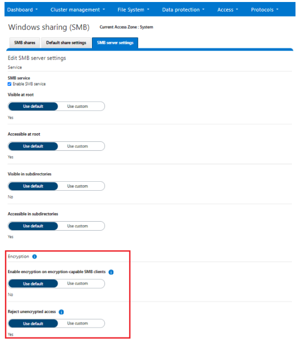
Author: Nick Trimbee

OneFS File Pool Policies
Thu, 13 Jan 2022 15:56:39 -0000
|Read Time: 0 minutes
A OneFS file pool policy can be easily generated from either the CLI or WebUI. For example, the following CLI syntax creates a policy which archives older files to a lower storage tier.
# isi filepool policies modify ARCHIVE_OLD --description "Move older files to archive storage" --data-storage-target TIER_A --data-ssd-strategy metadata-write --begin-filter --file-type=file --and --birth-time=2021-01-01 --operator=lt --and --accessed-time= 2021-09-01 --operator=lt --end-filter
After a file match with a File Pool policy occurs, the SmartPools job uses the settings in the matching policy to store and protect the file. However, a matching policy might not specify all settings for the match file. In this case, the default policy is used for those settings not specified in the custom policy. For each file stored on a cluster, the system needs to determine the following:
- Requested protection level
- Data storage target for local data cache
- SSD strategy for metadata and data
- Protection level for local data cache
- Configuration for snapshots
- SmartCache setting
- L3 cache setting
- Data access pattern
- CloudPools actions (if any)
If no File Pool policy matches a file, the default policy specifies all storage settings for the file. The default policy, in effect, matches all files not matched by any other SmartPools policy. For this reason, the default policy is the last in the file pool policy list, and, as such, always the last policy that SmartPools applies.
Next, SmartPools checks the file’s current settings against those the policy would assign to identify those which do not match. Once SmartPools has the complete list of settings that it needs to apply to that file, it sets them all simultaneously, and moves to restripe that file to reflect any and all changes to Node Pool, protection, SmartCache use, layout, etc.
Custom File Attributes, or user attributes, can be used when more granular control is needed than can be achieved using the standard file attributes options (File Name, Path, File Type, File Size, Modified Time, Create Time, Metadata Change Time, Access Time). User Attributes use key value pairs to tag files with additional identifying criteria which SmartPools can then use to apply File Pool policies. While SmartPools has no utility to set file attributes, this can be done easily by using the ‘setextattr’ command.
Custom File Attributes are generally used to designate ownership or create project affinities. Once set, they are leveraged by SmartPools just as File Name, File Type or any other file attribute to specify location, protection and performance access for a matching group of files.
For example, the following CLI commands can be used to set and verify the existence of the attribute ‘key1’ with value ‘val1’ on a file ‘attrib.txt’:
# setextattr user key1 val1 attrib.txt # getextattr user key1 attrib.txt file val1
A File Pool policy can be crafted to match and act upon a specific custom attribute and/or value.
For example, the File Policy below, created via the OneFS WebUI, will match files with the custom attribute ‘key1=val1’ and move them to the ‘Archive_1’ tier:
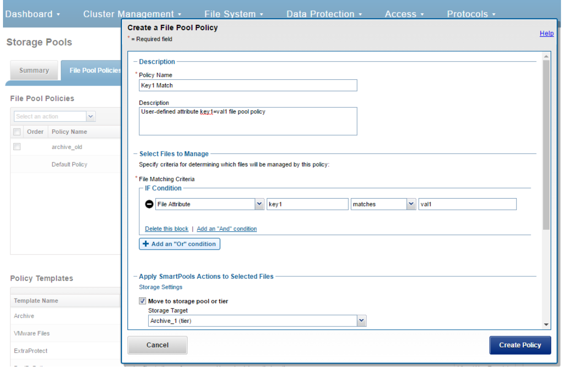
Once a subset of a cluster’s files have been marked with a custom attribute, either manually or as part of a custom application or workflow, they will then be moved to the Archive_1 tier upon the next successful run of the SmartPools job.
The file system explorer (and ‘isi get –D’ CLI command) provides a detailed view of where SmartPools-managed data is at any time by both the actual Node Pool location and the File Pool policy-dictated location (i.e. where that file will move after the next successful completion of the SmartPools job).
When data is written to the cluster, SmartPools writes it to a single Node Pool only. This means that, in almost all cases, a file exists in its entirety within a Node Pool, and not across Node Pools. SmartPools determines which pool to write to based on one of two situations:
- If a file matches a file pool policy based on directory path, that file will be written into the Node Pool dictated by the File Pool policy immediately.
- If a file matches a file pool policy which is based on any other criteria besides path name, SmartPools will write that file to the Node Pool with the most available capacity.
If the file matches a file pool policy that places it on a different Node Pool than the highest capacity Node Pool, it will be moved when the next scheduled SmartPools job runs.
For performance, charge back, ownership or security purposes it is sometimes important to know exactly where a specific file or group of files is on disk at any given time. While any file in a SmartPools environment typically exists entirely in one Storage Pool, there are exceptions when a single file may be split (usually only on a temporary basis) across two or more Node Pools at one time.
SmartPools generally only allows a file to reside in one Node Pool. A file may temporarily span several Node Pools in some situations. When a file Pool policy dictates a file move from one Node Pool to another, that file will exist partially on the source Node Pool and partially on the Destination Node Pool until the move is complete. If the Node Pool configuration is changed (for example, when splitting a Node Pool into two Node Pools) a file may be split across those two new pools until the next scheduled SmartPools job runs. If a Node Pool fills up and data spills over to another Node Pool so the cluster can continue accepting writes, a file may be split over the intended Node Pool and the default Spillover Node Pool. The last circumstance under which a file may span more than One Node Pool is for typical restriping activities like cross-Node Pool rebalances or rebuilds.
Author: Nick Trimbee

OneFS Path-based File Pool Policies
Thu, 13 Jan 2022 16:30:42 -0000
|Read Time: 0 minutes
As we saw in a previous article, when data is written to the cluster, SmartPools determines which pool to write to based on either path or on any other criteria.
If a file matches a file pool policy which is based on any other criteria besides path name, SmartPools will write that file to the Node Pool with the most available capacity.
However, if a file matches a file pool policy based on directory path, that file will be written into the Node Pool dictated by the File Pool policy immediately.
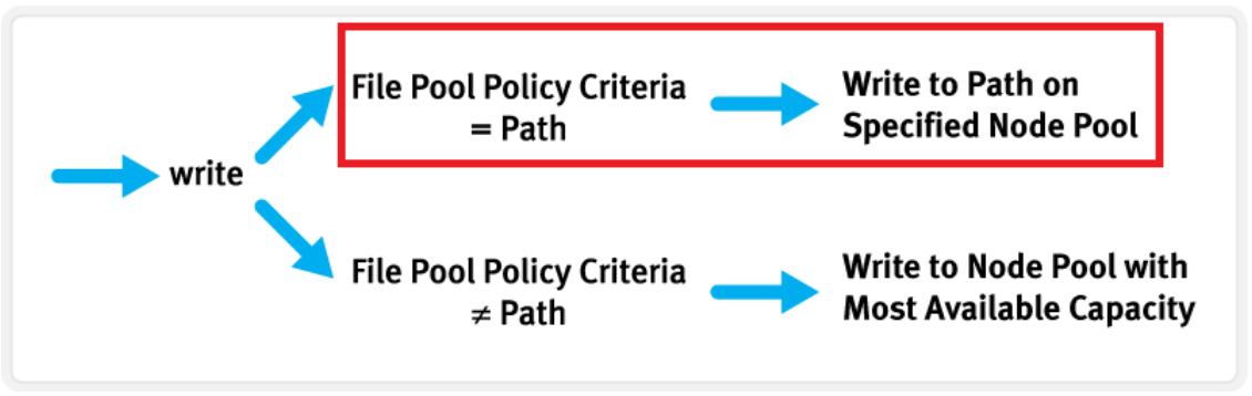
If the file matches a file pool policy that places it on a different Node Pool than the highest capacity Node Pool, it will be moved when the next scheduled SmartPools job runs.
If a filepool policy applies to a directory, any new files written to it will automatically inherit the settings from the parent directory. Typically, there is not much variance between the directory and the new file. So, assuming the settings are correct, the file is written straight to the desired pool or tier, with the appropriate protection, etc. This applies to access protocols like NFS and SMB, as well as copy commands like ‘cp’ issued directly from the OneFS command line interface (CLI). However, if the file settings differ from the parent directory, the SmartPools job will correct them and restripe the file. This will happen when the job next runs, rather than at the time of file creation.
However, simply moving a file into the directory (via the UNIX CLI commands such as cp, mv, etc.) will not occur until a SmartPools, SetProtectPlus, Multiscan, or Autobalance job runs to completion. Since these jobs can each perform a re-layout of data, this is when the files will be re-assigned to the desired pool. The file movement can be verified by running the following command from the OneFS CLI:
# isi get -dD <dir>
So the key is whether you’re doing a copy (that is, a new write) or not. As long as you’re doing writes and the parent directory of the destination has the appropriate file pool policy applied, you should get the behavior you want.
One thing to note: If the actual operation that is desired is really a move rather than a copy, it may be faster to change the file pool policy and then do a recursive “isi filepool apply –recurse” on the affected files.
There’s negligible difference between using an NFS or SMB client versus performing the copy on-cluster via the OneFS CLI. As mentioned above, using isi filepool apply will be slightly quicker than a straight copy and delete, since the copy is parallelized above the filesystem layer.
A file pool policy may be crafted which dictates that anything written to path /ifs/path1 is automatically moved directly to the Archive tier. This can easily be configured from the OneFS WebUI by navigating to File System > Storage Pools > File Pool Policies:
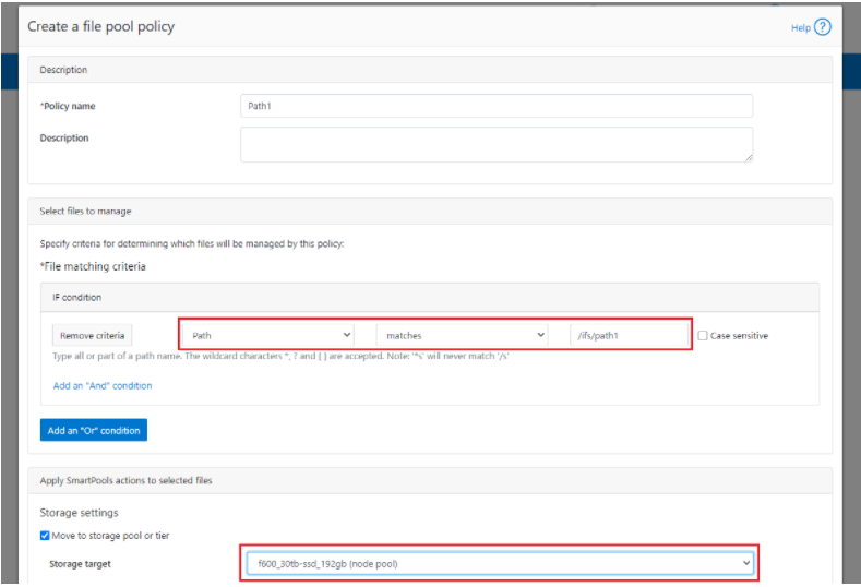
In the example above, a path based policy is created such that data written to /ifs/path1 will automatically be placed on the cluster’s F600 node pool.
For file Pool Policies that dictate placement of data based on its path, data typically lands on the correct node pool or tier without a SmartPools job running. File Pool Policies that dictate placement of data on other attributes besides path name get written to Disk Pool with the highest available capacity and then moved, if necessary, to match a File Pool policy, when the next SmartPools job runs. This ensures that write performance is not sacrificed for initial data placement.
Any data not covered by a File Pool policy is moved to a tier that can be selected as a default for exactly this purpose. If no Disk Pool has been selected for this purpose, SmartPools will default to the Node Pool with the most available capacity.
Be aware that, when reconfiguring an existing path-based filepool policy to target a different nodepool or tier, the change will not immediately take effect for the new incoming data. The directory where new files will be created must be updated first and there are a several options available to address this:
- Running the SmartPools job will achieve this. However, this can take a significant amount of time, as the job may entail restriping or migrating a large quantity of file data.
- Invoking the ’isi filepool apply <path>’ command on a single directory in question will do it very rapidly. This option is ideal for a single, or small number, of ‘incoming’ data directories.
- To update all directories in a given subtree, but not affect the files’ actual data layouts, use:
# isi filepool apply --dont-restripe --recurse /ifs/path1- OneFS also contains the SmartPoolsTree job engine job specifically for this purpose. This can be invoked as follows:
# isi job start SmartPoolsTree --directory-only --path /ifs/path
For example, a cluster has both an F600 pool and an A2000 pool. A directory (/ifs/path1) is created and a file (file1.txt) written to it:
# mkdir /ifs/path1 # cd !$; touch file1.txt
As we can see, this file is written to the default A2000 pool:
# isi get -DD /ifs/path1/file1.txt | grep -i pool * Disk pools: policy any pool group ID -> data target a2000_200tb_800gb-ssd_16gb:97(97), metadata target a2000_200tb_800gb-ssd_16gb:97(97)
Next, a path-based file pool policy is created such that files written to /ifs/test1 are automatically directed to the cluster’s F600 tier:
# isi filepool policies create test2 --begin-filter --path=/ifs/test1 --and --data-storage-target f600_30tb-ssd_192gb --end-filter
# isi filepool policies list Name Description CloudPools State ------------------------------------ Path1 No access ------------------------------------ Total: 1
# isi filepool policies view Path1 Name: Path1 Description: CloudPools State: No access CloudPools Details: Policy has no CloudPools actions Apply Order: 1 File Matching Pattern: Path == path1 (begins with) Set Requested Protection: - Data Access Pattern: - Enable Coalescer: - Enable Packing: - Data Storage Target: f600_30tb-ssd_192gb Data SSD Strategy: metadata Snapshot Storage Target: - Snapshot SSD Strategy: - Cloud Pool: - Cloud Compression Enabled: - Cloud Encryption Enabled: - Cloud Data Retention: - Cloud Incremental Backup Retention: - Cloud Full Backup Retention: - Cloud Accessibility: - Cloud Read Ahead: - Cloud Cache Expiration: - Cloud Writeback Frequency: - ID: Path1
The ‘isi filepool apply’ command is run on /ifs/path1 in order to activate the path-based file policy:
# isi filepool apply /ifs/path1
A file (file-new1.txt) is then created under /ifs/path1:
# touch /ifs/path1/file-new1.txt
An inspection shows that this file is written to the F600 pool, as expected per the Path1 file pool policy:
# isi get -DD /ifs/path1/file-new1.txt | grep -i pool * Disk pools: policy f600_30tb-ssd_192gb(9) -> data target f600_30tb-ssd_192gb:10(10), metadata target f600_30tb-ssd_192gb:10(10)
The legacy file (/ifs/path1/file1.txt) is still on the A2000 pool, despite the path-based policy. However, this policy can be enacted on pre-existing data by running the following:
# isi filepool apply --dont-restripe --recurse /ifs/path1
Now, the legacy files are also housed on the F600 pool, and any new writes to the /ifs/path1 directory will also be written to the F600s:
# isi get -DD file1.txt | grep -i pool * Disk pools: policy f600_30tb-ssd_192gb(9) -> data target a2000_200tb_800gb-ssd_16gb:97(97), metadata target a2000_200tb_800gb-ssd_16gb:97(97)
Author: Nick Trimbee

PowerScale Gen6 Chassis Hardware Resilience
Thu, 13 Jan 2022 16:48:24 -0000
|Read Time: 0 minutes
In this article, we’ll take a quick look at the OneFS journal and boot drive mirroring functionality in PowerScale chassis-based hardware:
PowerScale Gen6 platforms, such as the new H700/7000 and A300/3000, stores the local filesystem journal and its mirror in the DRAM of the battery backed compute node blade. Each 4RU Gen 6 chassis houses four nodes. These nodes comprise a ‘compute node blade’ (CPU, memory, NICs), plus drive containers, or sleds, for each.
A node’s file system journal is protected against sudden power loss or hardware failure by OneFS journal vault functionality – otherwise known as ‘powerfail memory persistence’ (PMP). PMP automatically stores the both the local journal and journal mirror on a separate flash drive across both nodes in a node pair:
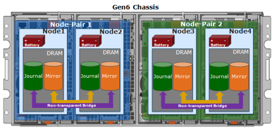
This journal de-staging process is known as ‘vaulting’, during which the journal is protected by a dedicated battery in each node until it’s safely written from DRAM to SSD on both nodes in a node-pair. With PMP, constant power isn’t required to protect the journal in a degraded state since the journal is saved to M.2 flash and mirrored on the partner node.
So, the mirrored journal is comprised of both hardware and software components, including the following constituent parts:
Journal Hardware Components
- System DRAM
- 2 Vault Flash
- Battery Backup Unit (BBU)
- Non-Transparent Bridge (NTB) PCIe link to partner node
- Clean copy on disk
Journal Software Components
- Power-fail Memory Persistence (PMP)
- Mirrored Non-volatile Interface (MNVI)
- IFS Journal + Node State Block (NSB)
- Utilities
Asynchronous DRAM Refresh (ADR) preserves RAM contents when the operating system is not running. ADR is important for preserving RAM journal contents across reboots, and it does not require any software coordination to do so.
The journal vault feature encompasses the hardware, firmware, and operating system support that ensure the journal’s contents are preserved across power failure. The mechanism is similar to the NVRAM controller on previous generation nodes but does not use a dedicated PCI card.
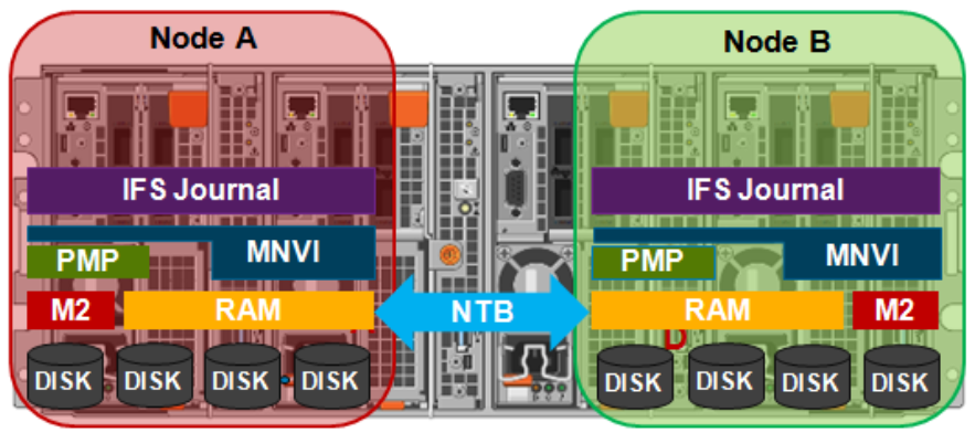
On power failure, the PMP vaulting functionality is responsible for copying both the local journal and the local copy of the partner node’s journal to persistent flash. On restoration of power, PMP is responsible for restoring the contents of both journals from flash to RAM and notifying the operating system.
A single dedicated flash device is attached via M.2 slot on the motherboard of the node’s compute module, residing under the battery backup unit (BBU) pack. To be serviced, the entire compute module must be removed.
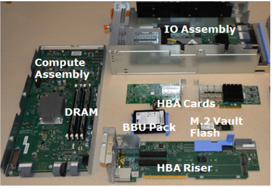
If the M.2 flash needs to be replaced for any reason, it will be properly partitioned and the PMP structure will be created as part of arming the node for vaulting.
The battery backup unit (BBU), when fully charged, provides enough power to vault both the local and partner journal during a power failure event.
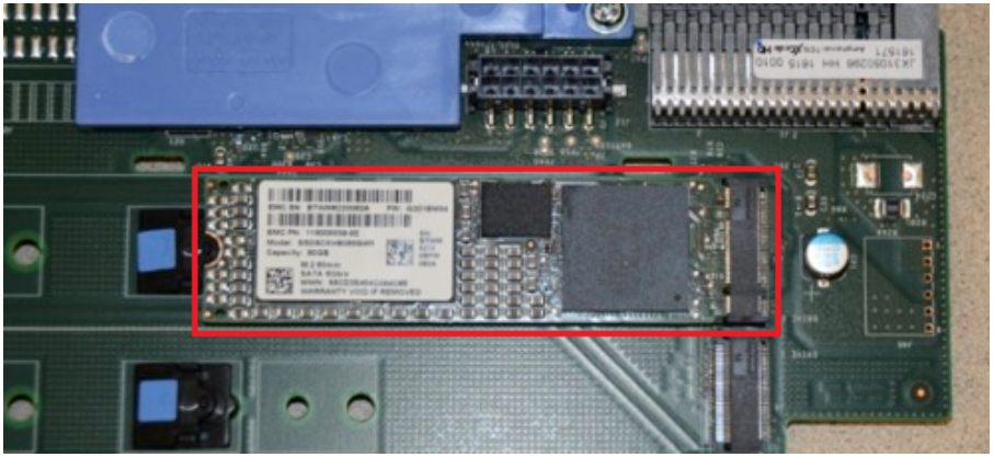
A single battery is utilized in the BBU, which also supports back-to-back vaulting.
On the software side, the journal’s Power-fail Memory Persistence (PMP) provides an equivalent to the NVRAM controller‘s vault/restore capabilities to preserve Journal. The PMP partition on the M.2 flash drive provides an interface between the OS and firmware.
If a node boots and its primary journal is found to be invalid for whatever reason, it has three paths for recourse:
- Recover journal from its M.2 vault.
- Recover journal from its disk backup copy.
- Recover journal from its partner node’s mirrored copy.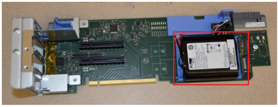
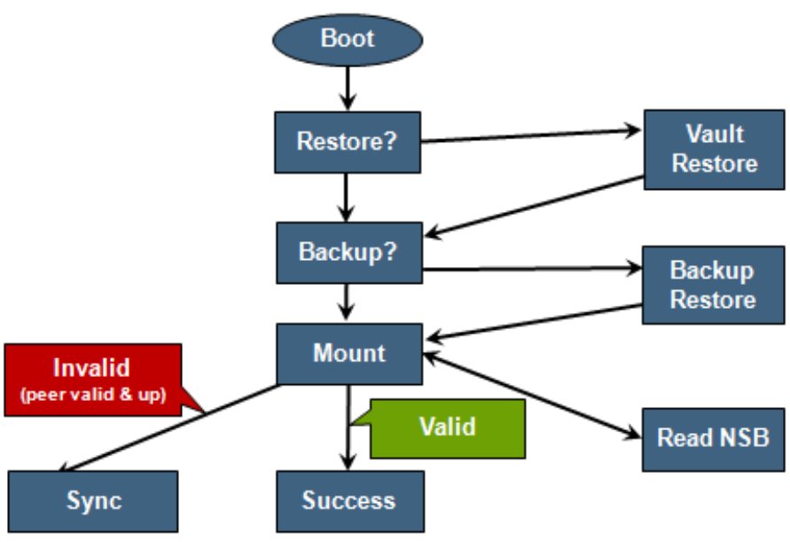
The mirrored journal must guard against rolling back to a stale copy of the journal on reboot. This necessitates storing information about the state of journal copies outside the journal. As such, the Node State Block (NSB) is a persistent disk block that stores local and remote journal status (clean/dirty, valid/invalid, etc), as well as other non-journal information. NSB stores this node status outside the journal itself and ensures that a node does not revert to a stale copy of the journal upon reboot.
Here’s the detail of an individual node’s compute module:
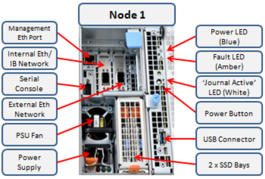
Of particular note is the ‘journal active’ LED, which is displayed as a white hand icon.

When this white hand icon is illuminated, it indicates that the mirrored journal is actively vaulting, and it is not safe to remove the node!
There is also a blue ‘power’ LED, and a yellow ‘fault’ LED per node. If the blue LED is off, the node may still be in standby mode, in which case it may still be possible to pull debug information from the baseboard management controller (BMC).
The flashing yellow ‘fault’ LED has several state indication frequencies:
Blink Speed | Blink Frequency | Indicator |
Fast blink | ¼ Hz | BIOS |
Medium blink | 1 Hz | Extended POST |
Slow blink | 4 Hz | Booting OS |
Off | Off | OS running |
The mirrored non-volatile interface (MNVI) sits below /ifs and above RAM and the NTB, provides the abstraction of a reliable memory device to the /ifs journal. MNVI is responsible for synchronizing journal contents to peer node RAM, at the direction of the journal, and persisting writes to both systems while in a paired state. It upcalls into the journal on NTB link events and notifies the journal of operation completion (mirror sync, block IO, etc.).
For example, when rebooting after a power outage, a node automatically loads the MNVI. It then establishes a link with its partner node and synchronizes its journal mirror across the PCIe Non-Transparent Bridge (NTB).
Prior to mounting /ifs, OneFS locates a valid copy of the journal from one of the following locations in order of preference:
Order | Journal Location | Description |
1st | Local disk | A local copy that has been backed up to disk |
2nd | Local vault | A local copy of the journal restored from Vault into DRAM |
3rd | Partner node | A mirror copy of the journal from the partner node |
If the node was shut down properly, it will boot using a local disk copy of the journal. The journal will be restored into DRAM and /ifs will mount. On the other hand, if the node suffered a power disruption the journal will be restored into DRAM from the M.2 vault flash instead (the PMP copies the journal into the M.2 vault during a power failure).
In the event that OneFS is unable to locate a valid journal on either the hard drives or M.2 flash on a node, it will retrieve a mirrored copy of the journal from its partner node over the NTB. This is referred to as ‘Sync-back’.
Note: Sync-back state only occurs when attempting to mount /ifs.
On booting, if a node detects that its journal mirror on the partner node is out of sync (invalid), but the local journal is clean, /ifs will continue to mount. Subsequent writes are then copied to the remote journal in a process known as ‘sync-forward’.
Here’s a list of the primary journal states:
Journal State | Description |
Sync-forward | State in which writes to a journal are mirrored to the partner node. |
Sync-back | Journal is copied back from the partner node. Only occurs when attempting to mount /ifs. |
Vaulting | Storing a copy of the journal on M.2 flash during power failure. Vaulting is performed by PMP. |
During normal operation, writes to the primary journal and its mirror are managed by the MNVI device module, which writes through local memory to the partner node’s journal via the NTB. If the NTB is unavailable for an extended period, write operations can still be completed successfully on each node. For example, if the NTB link goes down in the middle of a write operation, the local journal write operation will complete. Read operations are processed from local memory.
Additional journal protection for Gen 6 nodes is provided by OneFS powerfail memory persistence (PMP) functionality, which guards against PCI bus errors that can cause the NTB to fail. If an error is detected, the CPU requests a ‘persistent reset’, during which the memory state is protected and node rebooted. When back up again, the journal is marked as intact and no further repair action is needed.
If a node loses power, the hardware notifies the BMC, initiating a memory persistent shutdown. At this point the node is running on battery power. The node is forced to reboot and load the PMP module, which preserves its local journal and its partner’s mirrored journal by storing them on M.2 flash. The PMP module then disables the battery and powers itself off.
Once power is back on and the node restarted, the PMP module first restores the journal before attempting to mount /ifs. Once done, the node then continues through system boot, validating the journal, setting sync-forward or sync-back states, etc.
During boot, isi_checkjournal and isi_testjournal will invoke isi_pmp. If the M.2 vault devices are unformatted, isi_pmp will format the devices.
On clean shutdown, isi_save_journal stashes a backup copy of the /dev/mnv0 device on the root filesystem, just as it does for the NVRAM journals in previous generations of hardware.
If a mirrored journal issue is suspected, or notified via cluster alerts, the best place to start troubleshooting is to take a look at the node’s log events. The journal logs to /var/log/messages, with entries tagged as ‘journal_mirror’.
The following new CELOG events have also been added in OneFS 8.1 for cluster alerting about mirrored journal issues:
CELOG Event | Description |
HW_GEN6_NTB_LINK_OUTAGE | Non-transparent bridge (NTP) PCIe link is unavailable |
FILESYS_JOURNAL_VERIFY_FAILURE | No valid journal copy found on node |
Another reliability optimization for the Gen6 platform is boot mirroring. Gen6 does not use dedicated bootflash devices, as with previous generation nodes. Instead, OneFS boot and other OS partitions are stored on a node’s data drives. These OS partitions are always mirrored (except for crash dump partitions). The two mirrors protect against disk sled removal. Since each drive in a disk sled belongs to a separate disk pool, both elements of a mirror cannot live on the same sled.
The boot and other OS partitions are 8GB and reserved at the beginning of each data drive for boot mirrors. OneFS automatically rebalances these mirrors in anticipation of, and in response to, service events. Mirror rebalancing is triggered by drive events such as suspend, softfail and hard loss.
The following command will confirm that boot mirroring is working as intended:
# isi_mirrorctl verify
When it comes to smartfailing nodes, here are a couple of other things to be aware of with mirror journal and the Gen6 platform:
- When you smartfail a node in a node pair, you do not have to smartfail its partner node.
- A node will still run indefinitely with its partner missing. However, this significantly increases the window of risk since there’s no journal mirror to rely on (in addition to lack of redundant power supply, etc).
- If you do smartfail a single node in a pair, the journal is still protected by the vault and powerfail memory persistence.
Author: Nick Trimbee

OneFS Job Execution and Node Exclusion
Thu, 06 Jan 2022 23:26:13 -0000
|Read Time: 0 minutes
Up through OneFS 9.2, a job engine job was an all or nothing entity. Whenever a job ran, it involved the entire cluster – regardless of individual node type, load, or condition. As such, any nodes that were overloaded or in a degraded state could still impact the execution ability of the job at large.
To address this, OneFS 9.3 provides the capability to exclude one or more nodes from participating in running a job. This allows the temporary removal of any nodes with high load, or other issues, from the job execution pool so that jobs do not become stuck.
The majority of the OneFS job engine’s jobs have no default schedule and are typically manually started by a cluster administrator or process. Other jobs such as FSAnalyze, MediaScan, ShadowStoreDelete, and SmartPools, are normally started via a schedule. The job engine can also initiate certain jobs on its own. For example, if the SnapshotIQ process detects that a snapshot has been marked for deletion, it will automatically queue a SnapshotDelete job.
The Job Engine will also execute jobs in response to certain system event triggers. In the case of a cluster group change, for example the addition or subtraction of a node or drive, OneFS automatically informs the job engine, which responds by starting a FlexProtect job. The coordinator notices that the group change includes a newly-smart-failed device and then initiates a FlexProtect job in response.
Job administration and execution can be controlled via the WebUI, CLI, or platform API. A job can be started, stopped, paused and resumed, and this is managed via the job engines’ check-pointing system. For each of these control methods, additional administrative security can be configured using roles-based access control (RBAC).
The job engine’s impact control and work throttling mechanism can limit the rate at which individual jobs can run. Throttling is employed at a per-manager process level, so job impact can be managed both granularly and gracefully.
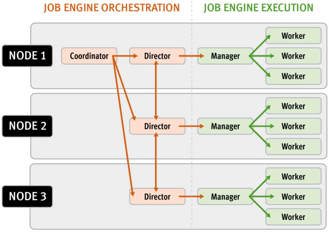
Every twenty seconds, the coordinator process gathers cluster CPU and individual disk I/O load data from all the nodes across the cluster. The coordinator uses this information, in combination with the job impact configuration, to decide how many threads can run on each cluster node to service each running job. This can be a fractional number, and fractional thread counts are achieved by having a thread sleep for a given percentage of each second.
Using this CPU and disk I/O load data, every sixty seconds the coordinator evaluates how busy the various nodes are and makes a job throttling decision, instructing the various job engine processes as to the action they need to take. This enables throttling to be sensitive to workloads in which CPU and disk I/O load metrics yield different results. There are also separate load thresholds tailored to the different classes of drives used in OneFS powered clusters, from capacity optimized SATA disks to flash-based SSDs.
Configuration is via the OneFS CLI and gconfig and is global, such that it applies to all jobs on startup. However, the exclusion configuration is not dynamic, and once a job is started with the final node set, there is no further reconfiguration permitted. So if a participant node is excluded, it will remain excluded until the job has completed. Similarly, if a participant needs to be excluded, the current job will have to be cancelled and a new job started. Any nodes can be excluded, including the node running the job engine’s coordinator process. The coordinator will still monitor the job, it just won’t spawn a manager for the job.
The list of participating nodes for a job are computed in three phases:
- Query the cluster’s GMP group.
- Call to job.get_participating_nodes to get a subset from the gmp group.
- Remove the nodes listed in core.excluded_participants from the subset.
The CLI syntax for configuring an excluded nodes list on a cluster is as follows (in this example, excluding nodes one through three):
# isi_gconfig –t job-config core.excluded_participants="{1,2,3}"The ‘excluded_participants’ are entered as a comma-separated devid value list with no spaces, specified within parentheses and double quotes. All excluded nodes must be specified in full, since there’s no aggregation. Note that, while the excluded participant configuration will be displayed via gconfig, it is not reported as part of the ‘sysctl efs.gmp.group’ output.
A job engine node exclusion configuration can be easily reset to avoid excluding any nodes by assigning the “{}” value.
# isi_gconfig –t job-config core.excluded_participants="{}"
A ‘core.excluded_participant_percent_warn’ parameter defines the maximum percentage of removed nodes.
# isi_gconfig -t job-config core.excluded_participant_percent_warn
core.excluded_participant_percent_warn (uint) = 10This parameter defaults to 10%, above which a CELOG event warning is generated.
As many nodes as desired can be removed from the job group. CELOG informational event will notify of removed nodes. If too many nodes have been removed (the gconfig parameter sets too many node thresholds), CELOG will fire a warning event. If some nodes are removed but they’re not part of the GMP group, a different warning event will trigger.
If all nodes are removed, a CLI/pAPI error will be returned, the job will fail, and a CELOG warning will fire. For example:
# isi job jobs start LinCount Job operation failed: The job had no participants left. Check core.excluded_participants setting and make sure there is at least one node to run the job: Invalid argument # isi job status 10 LinCount Failed 2021-10-24T:20:45:23 ------------------------------------------------------------------ Total: 9
Note, however, that the following core system maintenance jobs will continue to run across all nodes in a cluster even if a node exclusion has been configured:
- AutoBalance
- Collect
- FlexProtect
- MediaScan
- MultiScan
Author: Nick Trimbee

Setting Up PowerScale for Google Cloud SmartConnect
Wed, 29 Dec 2021 17:48:23 -0000
|Read Time: 0 minutes
In the Dell EMC PowerScale for Google Cloud solution, OneFS uses the cluster service FQDN as its SmartConnect Zone name with a round-robin client-connection balancing policy. The round-robin policy is a default setting and is recommended for most cases in OneFS. (For more details about the OneFS SmartConnect load-balancing policy, see the Load Balancing section of the white paper Dell EMC PowerScale: Network Design Considerations.)
After the cluster is deployed, you must find the OneFS SmartConnect service IP in the clusters page within Google Cloud Console. Then, configure your DNS server to delegate the cluster service FQDN zone to the OneFS Service IP. You need to configure a forwarding rule in Google Cloud DNS which forwards the cluster service FQDN query to the DNS server, and set up a zone delegation on the DNS server that points to the cluster service IP. The following figure shows the DNS query flow by leveraging Google Cloud DNS along with a DNS server in the project.
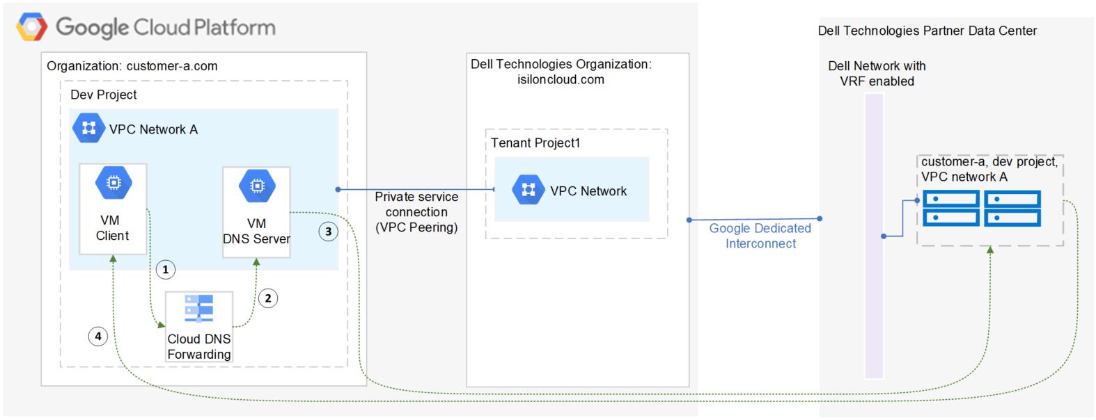
- VM clients send a DNS request for Cluster service FQDN to the Google Cloud DNS service.
- Google Cloud DNS forwards the request to the DNS server.
- The DNS server forwards the request to the cluster service IP. The service IP is responsible for translating the cluster service IP into an available node IP.
- SmartConnect returns a node IP to the client. The client can now access cluster data.
Because Google Cloud DNS cannot communicate with the OneFS cluster directly, we use a DNS server that is located in the authorized VPC network to forward the SmartConnect DNS request to the cluster. You can use either a Windows server or a Linux server. In this blog we use a Windows server to show the detailed steps.
Obtain required cluster information
The following information is required before setting up SmartConnect:
- Cluster service FQDN -- This is the OneFS SmartConnect zone name used by clients.
- Service IP -- This is the OneFS SmartConnect service IP that is responsible for resolving the client DNS request and returning an available node IP to clients.
- Authorized network -- By default, only the machines on an authorized VPC network can access a PowerScale cluster.
To obtain this required information, do the following:
- In the Google Cloud Console navigation menu, click PowerScale and then click Clusters.
- Find your cluster row, where you can see the cluster service FQDN and service IP:
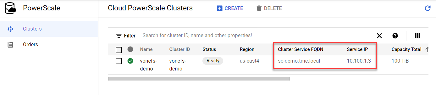
3. To find the authorized network information, click the name of the cluster. From the PowerScale Cluster Details page, find the authorized network from the Network information, highlighted here:
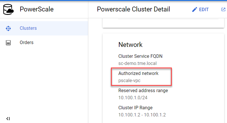
Set up a DNS server
If you already have an available DNS server that is connected to the cluster authorized network, you can use this existing DNS server and skip Step 1 and Step 2 below.
- In the Google Cloud Console navigation menu, click Compute Engine and then click VM instances. In this example, we are creating a Windows VM instance as a DNS server. Make sure your DNS server is connected to the cluster authorized network.
- Log into the DNS server and install DNS Server Role in the Windows machine. (If you are using a Linux machine, you can use Bind software instead.)
- Create a new DNS zone in the DNS server:
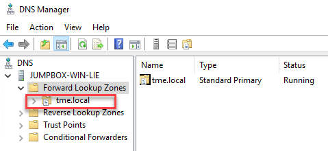
4. Create an (A) record for the cluster service IP. (See the section DNS delegation best practices of the white paper Dell EMC PowerScale: Network Design Considerations for more details.)
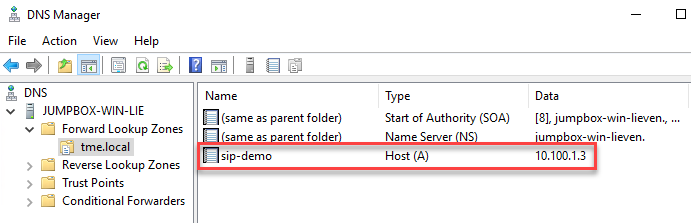
5. Create a new delegation for your cluster service FQDN (sc-demo.tme.local in this example) and point the delegation server to your cluster service IP (A) record created above (sip-demo.tme.local in this example), as shown here:
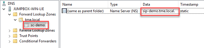
Configure Cloud DNS and firewall rules
- In the Google Cloud Console navigation menu, click Network services and then click Cloud DNS.
- Click the CREATE ZONE button.
- Choose the Private zone type and enter your Cluster Service FQDN in the DNS name field. Choose Forward queries to another server and your cluster authorized network, as shown here:
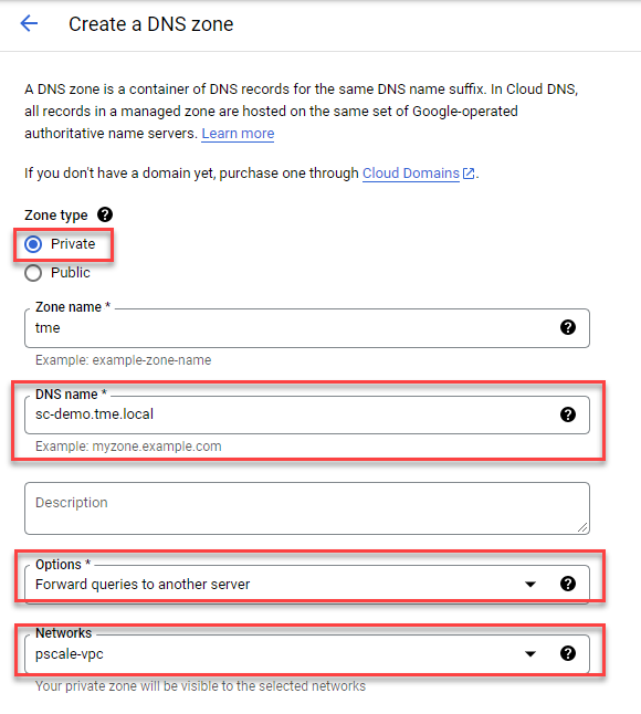
4. Obtain the DNS server IP address that you configured in the ‘Set up a DNS server’ step.
5. Point the destination DNS server to your own DNS server IP address, then click the Create button.

6. Add firewall rules to allow ingress DNS traffic to your DNS server from Cloud DNS. In the Google Cloud Console navigation menu, click VPC network and then click Firewall.
7. Click the CREATE FIREWALL RULE button.
8. Create a new Firewall rule and include the following options:
- In the Network field, make sure the cluster authorized network is selected.
- Source filter: IPv4 ranges
- Source IPv4 ranges: 35.199.192.0/19. This is the IP range Cloud DNS requests will originate from. See Cloud DNS zones overview for more details.
- Protocols and ports: TCP 53 and UDP 53.
See the following example:
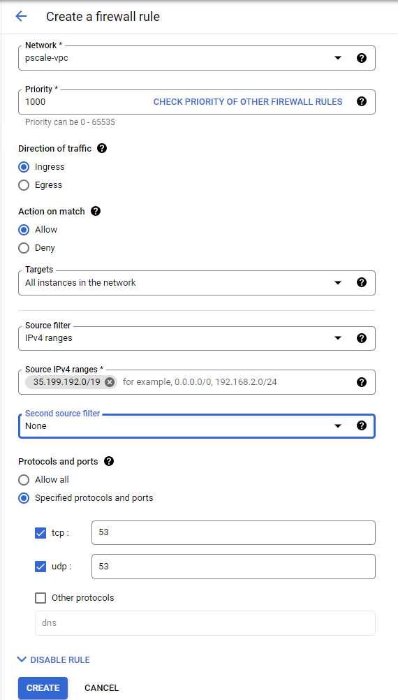
4. The resulting firewall rule in Google Cloud will appear as follows:
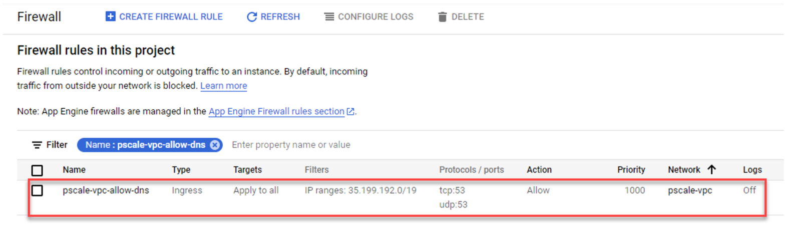
Verify your SmartConnect
- Log into a VM instance that is connected to an authorized network. (This example uses a Linux machine.)
- Resolve the cluster service FQDN via nslookup and mount a file share via NFS.
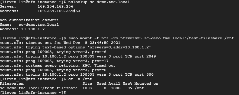
Conclusion
PowerScale cluster is a distributed file system composed of multiple nodes. We always recommend using the SmartConnect feature to balance the client connections to all cluster nodes. This way, you can maximize PowerScale cluster performance to provide maximum value to your business. Try it now in your Dell EMC PowerScale for Google Cloud solution.
Author: Lieven Lin

Live Broadcast Recording Using OneFS for Google Cloud, Gallery SIENNA ND, and Adobe Premiere Pro
Fri, 07 Jan 2022 14:03:44 -0000
|Read Time: 0 minutes
Here at Dell Technologies, we tested a cloud native real-time NDI ISO feed ingest workflow based on Gallery SIENNA, OneFS, and Adobe Premiere Pro, all running natively in Google Cloud.
TL; DR... it's awesome!
Mark Gilbert (CTO at Gallery SIENNA) had noticed there was a growing demand in the market for highly scalable, enterprise-grade file storage in the public cloud for ISO recording. So, we were excited to test this much-needed solution.
Sure, we could have just spun up a cloud-compute instance, created some SMB shares or NFS exports on it, and off you go. But then you quickly find that your ability to scale becomes an issue.
Arguably, the most critical part of any live broadcast is the bulk recording of ISO feeds, and as camera technology improves, recorded data is growing at an ever-increasing pace. Resolutions are increasing, frame rates are faster and internet connection pipes are getting larger.
This is where OneFS for Google Cloud steps in.
Remote production is now a must rather than a nice-to-have for every studio. The production world has had to adopt it, embrace it and buckle in for the ride. There are some great products out there to help businesses enable remote-production workflows. Gallery SIENNA is one of these products. It enables NDI-from-anywhere workflows that help to reduce utilization on over-contended connections.
You can purchase OneFS for Google Cloud through the Google Cloud Marketplace, attach it to a Gallery SIENNA Processing Engine via NFS export and start recording at the click of a button. In our testing, as soon as the recorders began writing, we were able to open and manipulate the files in Adobe Premiere Pro, which we connected to via SMB to prove out that multi-protocol worked too. This was all while the files were being recorded, and we could expand them in real-time in the timeline as they grow.
Infrastructure components (provisioned in Google Cloud):
- 1 x OneFS for Google Cloud
- 1 x Ubuntu VM
- Running Gallery SIENNA ND Processing Engine
- 1 x Windows 10 VM
- NDI Tools
- Adobe Premiere Pro
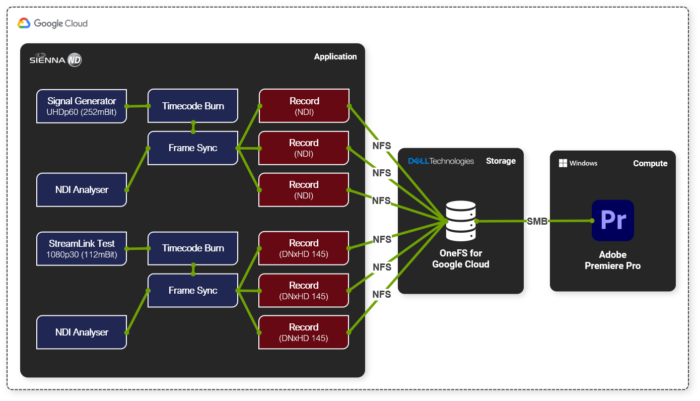
We used a SIENNA ND Processing Engine to generate six real-time record feeds, three of which were 3840p60 NDI and the other three of 1080p30 DNxHD 145
One of the great benefits of using Gallery SIENNA ND on Google Cloud is that our ingest could have come from anywhere. We could have used any internet-connected device that can reach the Google Cloud instance, be that a static connection in a purpose-built facility or a 4G/5G cell phone camera on the street with the NDI tools on it.
High-level workflow:
- Added a Signal Generator node (3840p60) into our SIENNA ND Processing Engine instance
- Used the SIENNA ND node-based architecture to add on a timecode burn and frame sync
- Added 3 x <NDI Recorder>
- Configured the recorders to write out to an NFS export on our OneFS for Google Cloud instance
- Added a StreamLink Test node (1080p30) into the same SIENNA ND Processing Engine instance
- Added timecode burn and frame sync nodes again
- Added 3 x <DNxHD 145 Recorder>
- Configured the recorders to write out to the same NFS export on our OneFS for Google Cloud instance
- Hit record on all recorders
Once the record was running, we added a "Media Picker" node and selected one of the files that we were recording. Then, we connected this growing file and one of the frame-sync outputs to a "multiviewer" node. We then watched both the live feed and chase play from disk as it was being laid down.
To cap it off, we also mounted one of the output paths using SMB from a Google Cloud hosted Windows 10 instance running Adobe Premiere Pro, and we were able to import, scrub and expand the files as they grew in real-time, allowing us to chase edit.
To find out more about the Dell Technologies offers for Media and Entertainment, feel free to get in touch by DM, or click here to find one of our experts in your time zone.
See the following links for more information about OneFS for Google Cloud and Gallery SIENNA.
Author: Andy Copeland

OneFS Data Inlining – Performance and Monitoring
Tue, 16 Nov 2021 19:57:36 -0000
|Read Time: 0 minutes
In the second of this series of articles on data inlining, we’ll shift the focus to monitoring and performance.
The storage efficiency potential of inode inlining can be significant for data sets comprising large numbers of small files, which would have required a separate inode and data blocks for housing these files prior to OneFS 9.3.
Latency-wise, the write performance for inlined file writes is typically comparable or slightly better as compared to regular files, because OneFS does not have to allocate extra blocks and protect them. This is also true for reads, because OneFS doesn’t have to search for and retrieve any blocks beyond the inode itself. This also frees up space in the OneFS read caching layers, as well as on disk, in addition to requiring fewer CPU cycles.
The following figure illustrates the levels of indirection a file access request takes to get to its data. Unlike a standard file, an inline file skips the later stages of the path, which involve the inode metatree redirection to the remote data blocks.
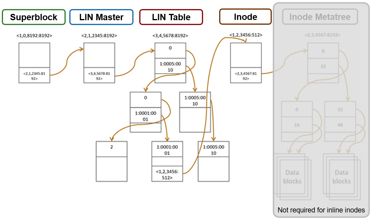
Access starts with the Superblock, which is located at multiple fixed block addresses on each drive in the cluster. The Superblock contains the address locations of the LIN Master block, which contains the root of the LIN B+ Tree (LIN table). The LIN B+Tree maps logical inode numbers to the actual inode addresses on disk, which, in the case of an inlined file, also contains the data. This saves the overhead of finding the address locations of the file’s data blocks and retrieving data from them.
For hybrid nodes with sufficient SSD capacity, using the metadata-write SSD strategy automatically places inlined small files on flash media. However, because the SSDs on hybrid nodes default to 512byte formatting, when using metadata read/write strategies, you must set the ‘–force-8k-inodes’ flag for these SSD metadata pools in order for files to be inlined. This can be a useful performance configuration for small file HPC workloads, such as EDA, for data that is not residing on an all-flash tier. But keep in mind that forcing 8KB inodes on a hybrid pool’s SSDs will result in a considerable reduction in available inode capacity than would be available with the default 512 byte inode configuration.
You can use the OneFS ‘isi_drivenum’ CLI command to verify the drive block sizes in a node. For example, the following output for a PowerScale Gen6 H-series node shows drive Bay 1 containing an SSD with 4KB physical formatting and 512byte logical sizes, and Bays A to E comprising hard disks (HDDs) with both 4KB logical and physical formatting.
# isi_drivenum -bz Bay 1 Physical Block Size: 4096 Logical Block Size: 512 Bay 2 Physical Block Size: N/A Logical Block Size: N/A Bay A0 Physical Block Size: 4096 Logical Block Size: 4096 Bay A1 Physical Block Size: 4096 Logical Block Size: 4096 Bay A2 Physical Block Size: 4096 Logical Block Size: 4096 Bay B0 Physical Block Size: 4096 Logical Block Size: 4096 Bay B1 Physical Block Size: 4096 Logical Block Size: 4096 Bay B2 Physical Block Size: 4096 Logical Block Size: 4096 Bay C0 Physical Block Size: 4096 Logical Block Size: 4096 Bay C1 Physical Block Size: 4096 Logical Block Size: 4096 Bay C2 Physical Block Size: 4096 Logical Block Size: 4096 Bay D0 Physical Block Size: 4096 Logical Block Size: 4096 Bay D1 Physical Block Size: 4096 Logical Block Size: 4096 Bay D2 Physical Block Size: 4096 Logical Block Size: 4096 Bay E0 Physical Block Size: 4096 Logical Block Size: 4096 Bay E1 Physical Block Size: 4096 Logical Block Size: 4096 Bay E2 Physical Block Size: 4096 Logical Block Size: 4096
Note that the SSD disk pools used in PowerScale hybrid nodes that are configured for meta-read or meta-write SSD strategies use 512 byte inodes by default. This can significantly save space on these pools, because they often have limited capacity, but it will prevent data inlining from occurring. By contrast, PowerScale all-flash nodepools are configured by default for 8KB inodes.
The OneFS ‘isi get’ CLI command provides a convenient method to verify which size inodes are in use in a given node pool. The command’s output includes both the inode mirrors size and the inline status of a file.
When it comes to efficiency reporting, OneFS 9.3 provides three CLI improved tools for validating and reporting the presence and benefits of data inlining, namely:
- The ‘isi statistics data-reduction’ CLI command has been enhanced to report inlined data metrics, including both a capacity saved and an inlined data efficiency ratio:
# isi statistics data-reduction Recent Writes Cluster Data Reduction (5 mins) --------------------- ------------- ---------------------- Logical data 90.16G 18.05T Zero-removal saved 0 - Deduplication saved 5.25G 624.51G Compression saved 2.08G 303.46G Inlined data saved 1.35G 2.83T Preprotected physical 82.83G 14.32T Protection overhead 13.92G 2.13T Protected physical 96.74G 26.28T Zero removal ratio 1.00 : 1 - Deduplication ratio 1.06 : 1 1.03 : 1 Compression ratio 1.03 : 1 1.02 : 1 Data reduction ratio 1.09 : 1 1.05 : 1 Inlined data ratio 1.02 : 1 1.20 : 1 Efficiency ratio 0.93 : 1 0.69 : 1
Be aware that the effect of data inlining is not included in the data reduction ratio because it is not actually reducing the data in any way – just relocating it and protecting it more efficiently. However, data inlining is included in the overall storage efficiency ratio.
The ‘inline data saved’ value represents the count of files which have been inlined, multiplied by 8KB (inode size). This value is required to make the compression ratio and data reduction ratio correct.
- The ‘isi_cstats’ CLI command now includes the accounted number of inlined files within /ifs, which is displayed by default in its console output.
# isi_cstats
Total files : 397234451
Total inlined files : 379948336
Total directories : 32380092
Total logical data : 18471 GB
Total shadowed data : 624 GB
Total physical data : 26890 GB
Total reduced data : 14645 GB
Total protection data : 2181 GB
Total inode data : 9748 GB
Current logical data : 18471 GB
Current shadowed data : 624 GB
Current physical data : 26878 GB
Snapshot logical data : 0 B
Snapshot shadowed data : 0 B
Snapshot physical data : 32768 B
Total inlined data savings : 2899 GB
Total inlined data ratio : 1.1979 : 1
Total compression savings : 303 GB
Total compression ratio : 1.0173 : 1
Total deduplication savings : 624 GB
Total deduplication ratio : 1.0350 : 1
Total containerized data : 0 B
Total container efficiency : 1.0000 : 1
Total data reduction ratio : 1.0529 : 1
Total storage efficiency : 0.6869 : 1
Raw counts
{ type=bsin files=3889 lsize=314023936 pblk=1596633 refs=81840315 data=18449 prot=25474 ibyte=23381504 fsize=8351563907072 iblocks=0 }
{ type=csin files=0 lsize=0 pblk=0 refs=0 data=0 prot=0 ibyte=0 fsize=0 iblocks=0 }
{ type=hdir files=32380091 lsize=0 pblk=35537884 refs=0 data=0 prot=0 ibyte=1020737587200 fsize=0 iblocks=0 }
{ type=hfile files=397230562 lsize=19832702476288 pblk=2209730024 refs=81801976 data=1919481750 prot=285828971 ibyte=9446188553728 fsize=17202141701528 iblocks=379948336 }
{ type=sdir files=1 lsize=0 pblk=0 refs=0 data=0 prot=0 ibyte=32768 fsize=0 iblocks=0 }
{ type=sfile files=0 lsize=0 pblk=0 refs=0 data=0 prot=0 ibyte=0 fsize=0 iblocks=0 }- The ‘isi get’ CLI command can be used to determine whether a file has been inlined. The output reports a file’s logical ‘size’, but indicates that it consumes zero physical, data, and protection blocks. There is now also an ‘inlined data’ attribute further down in the output that also confirms that the file is inlined.
# isi get -DD file1 * Size: 2 * Physical Blocks: 0 * Phys. Data Blocks: 0 * Protection Blocks: 0 * Logical Size: 8192 PROTECTION GROUPS * Dynamic Attributes (6 bytes): * ATTRIBUTE OFFSET SIZE Policy Domains 0 6 INLINED DATA 0,0,0:8192[DIRTY]#1
So, in summary, some considerations and recommended practices for data inlining in OneFS 9.3 include the following:
- Data inlining is opportunistic and is only supported on node pools with 8KB inodes.
- No additional software, hardware, or licenses are required for data inlining.
- There are no CLI or WebUI management controls for data inlining.
- Data inlining is automatically enabled on applicable nodepools after an upgrade to OneFS 9.3 is committed.
- However, data inlining occurs for new writes and OneFS 9.3 does not perform any inlining during the upgrade process. Any applicable small files are instead inlined upon their first write.
- Since inode inlining is automatically enabled globally on clusters running OneFS 9.3, OneFS recognizes any diskpools with 512 byte inodes and transparently avoids inlining data on them.
- In OneFS 9.3, data inlining is not performed on regular files during tiering, truncation, upgrade, and so on.
- CloudPools Smartlink stubs, sparse files, and writable snapshot files are also not candidates for data inlining in OneFS 9.3.
- OneFS shadow stores do not apply data inlining. As such:
- Small file packing is disabled for inlined data files.
- Cloning works as expected with inlined data files.
- Inlined data files do not apply deduping. Non-inlined data files that are once deduped will not inline afterwards.
- Certain operations may cause data inlining to be reversed, such as moving files from an 8KB diskpool to a 512 byte diskpool, forcefully allocating blocks on a file, sparse punching, and so on.
The new OneFS 9.3 data inlining feature delivers on the promise of small file storage efficiency at scale, providing significant storage cost savings, without sacrificing performance, ease of use, or data protection.
Author: Nick Trimbee

OneFS Small File Data Inlining
Tue, 16 Nov 2021 19:41:09 -0000
|Read Time: 0 minutes
OneFS 9.3 introduces a new filesystem storage efficiency feature that stores a small file’s data within the inode, rather than allocating additional storage space. The principal benefits of data inlining in OneFS include:
- Reduced storage capacity utilization for small file datasets, generating an improved cost per TB ratio
- Dramatically improved SSD wear life
- Potential read and write performance improvement for small files
- Zero configuration, adaptive operation, and full transparency at the OneFS file system level
- Broad compatibility with other OneFS data services, including compression and deduplication
Data inlining explicitly avoids allocation during write operations because small files do not require any data or protection blocks for their storage. Instead, the file content is stored directly in unused space within the file’s inode. This approach is also highly flash media friendly because it significantly reduces the quantity of writes to SSD drives.
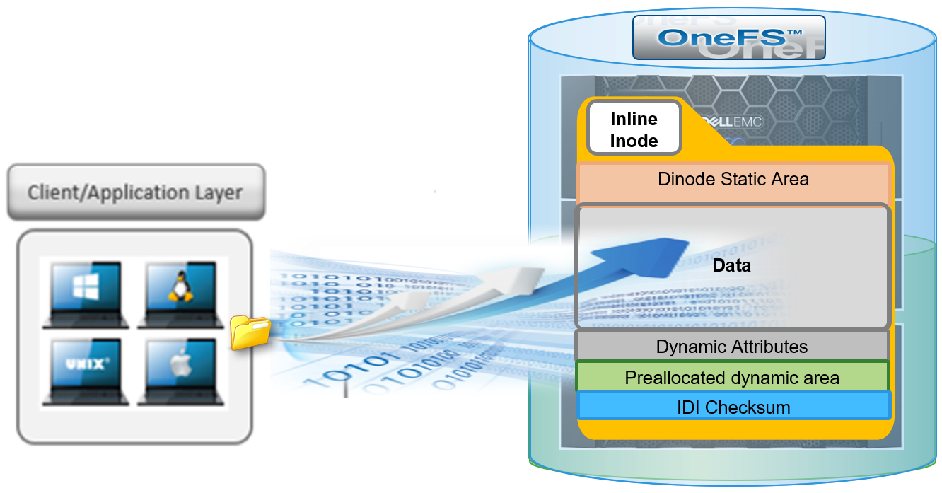
OneFS inodes, or index nodes, are a special class of data structure that store file attributes and pointers to file data locations on disk. They serve a similar purpose to traditional UNIX file system inodes, but also have some additional unique properties. Each file system object, whether it be a file, directory, symbolic link, alternate data stream container, or shadow store, is represented by an inode.
Within OneFS, SSD node pools in F series all-flash nodes always use 8KB inodes. For hybrid and archive platforms, the HDD node pools are either 512 bytes or 8KB in size, and this is determined by the physical and logical block size of the hard drives or SSDs in a node pool.
There are three different styles of drive formatting used in OneFS nodes, depending on the manufacturer’s specifications:
Drive Formatting | Characteristics |
Native 4Kn (native) | A native 4Kn drive has both a physical and logical block size of 4096B. |
512n (native) | A drive that has both physical and logical size of 512 is a native 512B drive. |
512e (emulated) | A 512e (512 byte-emulated) drive has a physical block size of 4096, but a logical block size of 512B. |
If the drives in a cluster’s nodepool are native 4Kn formatted, by default the inodes on this nodepool will be 8KB in size. Alternatively, if the drives are 512e formatted, then inodes by default will be 512B in size. However, they can also be reconfigured to 8KB in size if the ‘force-8k-inodes’ setting is set to true.
A OneFS inode is composed of several sections. These include:
- A static area, which is typically 134 bytes in size and contains fixed-width, commonly used attributes like POSIX mode bits, owner, and file size.
- Next, the regular inode contains a metatree cache, which is used to translate a file operation directly into the appropriate protection group. However, for inline inodes, the metatree is no longer required, so data is stored directly in this area instead.
- Following this is a preallocated dynamic inode area where the primary attributes, such as OneFS ACLs, protection policies, embedded B+ Tree roots, timestamps, and so on, are cached.
- And lastly a sector where the IDI checksum code is stored.
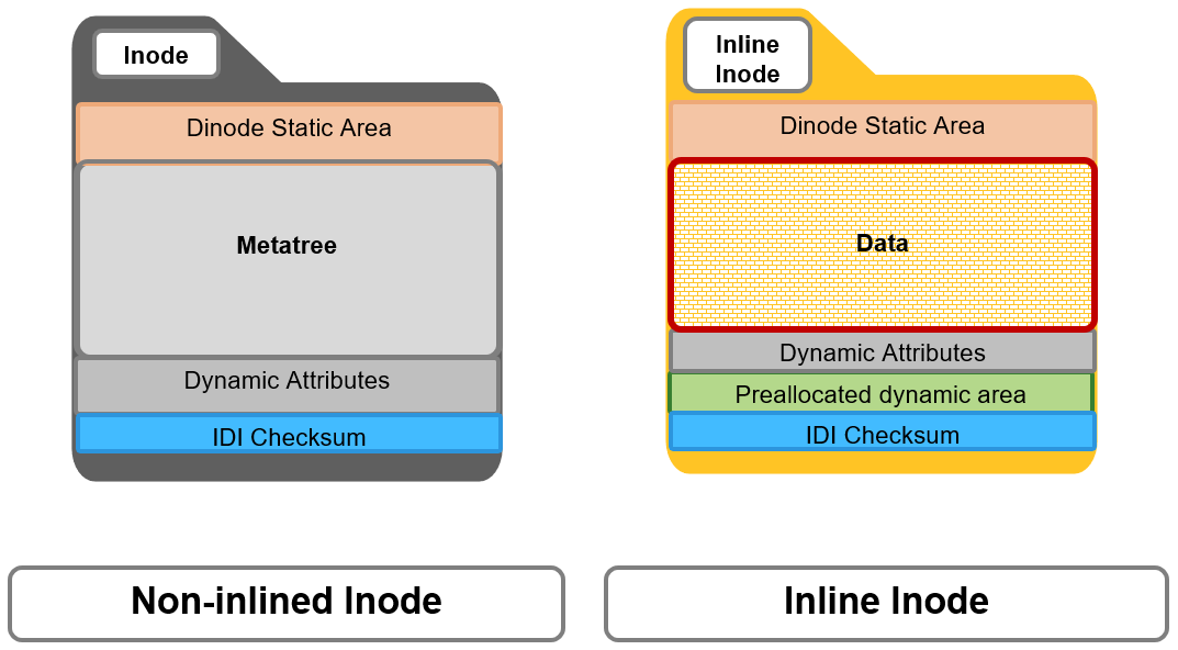
When a file write coming from the writeback cache, or coalescer, is determined to be a candidate for data inlining, it goes through a fast write path in BSW (BAM safe write - the standard OneFS write path). Compression will be applied, if appropriate, before the inline data is written to storage.

The read path for inlined files is similar to that for regular files. However, if the file data is not already available in the caching layers, it is read directly from the inode, rather than from separate disk blocks as with regular files.

Protection for inlined data operates the same way as for other inodes and involves mirroring. OneFS uses mirroring as protection for all metadata because it is simple and does not require the additional processing overhead of erasure coding. The number of inode mirrors is determined by the nodepool’s achieved protection policy, according to the following table:
OneFS Protection Level | Number of Inode Mirrors |
+1n | 2 inodes per file |
+2d:1n | 3 inodes per file |
+2n | 3 inodes per file |
+3d:1n | 4 inodes per file |
+3d:1n1d | 4 inodes per file |
+3n | 4 inodes per file |
+4d:1n | 5 inodes per file |
+4d:2n | 5 inodes per file |
+4n | 5 inodes per file |
Unlike file inodes above, directory inodes, which comprise the OneFS single namespace, are mirrored at one level higher than the achieved protection policy. The root of the LIN Tree is the most critical metadata type and is always mirrored at 8x.
Data inlining is automatically enabled by default on all 8KB formatted nodepools for clusters running OneFS 9.3, and does not require any additional software, hardware, or product licenses in order to operate. Its operation is fully transparent and, as such, there are no OneFS CLI or WebUI controls to configure or manage inlining.
In order to upgrade to OneFS 9.3 and benefit from data inlining, the cluster must be running a minimum OneFS 8.2.1 or later. A full upgrade commit to OneFS 9.3 is required before inlining becomes operational.
Be aware that data inlining in OneFS 9.3 does have some notable caveats. Specifically, data inlining will not be performed in the following instances:
- When upgrading to OneFS 9.3 from an earlier release which does not support inlining
- During restriping operations, such as SmartPools tiering, when data is moved from a 512 byte diskpool to an 8KB diskpool
- Writing CloudPools SmartLink stub files
- On file truncation down to non-zero size
- Sparse files (for example, NDMP sparse punch files) where allocated blocks are replaced with sparse blocks at various file offsets
- For files within a writable snapshot
Similarly, in OneFS 9.3 the following operations may cause inlined data inlining to be undone, or spilled:
- Restriping from an 8KB diskpool to a 512 byte diskpool
- Forcefully allocating blocks on a file (for example, using the POSIX ‘madvise’ system call)
- Sparse punching a file
- Enabling CloudPools BCM (BAM cache manager) on a file
These caveats will be addressed in a future release.
Author: Nick Trimbee

Boosting Storage Performance for Media and Entertainment with RDMA
Wed, 24 Apr 2024 13:04:15 -0000
|Read Time: 0 minutes
We are in a new golden era of content creation. The explosion of streaming services has brought an unprecedented volume of new and amazing media. Production, post-production, visual effects, animation, finishing: everyone is booked solid with work. And the expectations for this content are higher than ever, with new technically challenging formats becoming the norm rather than the exception. Anyone who has had to work with this content knows that even in 2021, working natively with 8K video or high frame rate 4K video is no joke.
During post, storage and workstation performance can be huge bottlenecks. These bottlenecks can be particularly painful for “hero” seats that are tasked with working in real time with uncompressed media.
So, let’s look at a new PowerScale OneFS 9.2 feature that can improve storage and workstation performance simultaneously. That technology is Remote Direct Memory Access (RDMA), and specifically NFS over RDMA.
Why NFS? Linux is still the operating system of choice for the applications that media professionals use to work with the most challenging media. Even if those applications have Windows or macOS variants, the Linux version is what is used in the truly high-end. And the native way for a Linux computer to access network storage is NFS. In particular, NFS over TCP.
Already this article is going down a rabbit hole of acronyms! I imagine that most people reading are already familiar with NFS (and SMB) and TCP (and UDP) and on and on. For the benefit of those folks who are not, NFS stands for Network File System. NFS is how Linux systems talk to network storage (there are other ways, but mostly, it is NFS). NFS traffic sits on top of other lower-level network protocols, in particular TCP (or UDP, but mostly it is TCP). TCP does a great job of handling things like packet loss on congested networks, but that comes with performance implications. Back to RDMA.
As the name implies, RDMA is a protocol that allows for a client system to copy data from a storage server’s memory directly into that client’s own memory. And in doing so, the client system bypasses many of the buffering layers inherent in TCP. This direct communication improves storage throughput and reduces latency in moving data between server and client. It also reduces CPU load on both the client and storage server.
RDMA was developed in the 1990s to support high performance compute workloads running over InfiniBand networks. In the 2000s, two methods of running RDMA over Ethernet networks were developed: iWARP and RoCE. Without going into too much detail, iWARP uses TCP for RDMA communications and RoCE uses UDP. There are various benefits and drawbacks of these two approaches. iWARP’s reliance on TCP allows for greater flexibility in network design, but suffers from many of the same performance drawbacks of native TCP communications. RoCE has reduced CPU overhead as compared to iWARP, but requires a lossless network. Once again, without going into too much detail, RoCE is the clear winner given that we are looking for the maximum storage performance with the lowest CPU load. And that is exactly what PowerScale OneFS uses, RoCE (actually RoCEv2, also known as Routable RoCE or RRoCE).
So, put that all together, and you can run NFS traffic over RDMA leveraging RoCE! Yes, back into alphabet soup land. But what this means is that if your environment and PowerScale storage nodes support it, you can massively boost performance by mounting the network storage with a few mount options. And that is a neat trick. The performance gains of RDMA are impressive. In some cases, RDMA is twice as performant as TCP, all other things being equal (with a similar drop in workstation utilization).
A good place to start learning if your PowerScale nodes support RDMA is my colleague Nick Trimbee’s excellent blog: Unstructured Data Tips.
Let’s bring this back to media creation and look at some real-world examples that were tested for this article. The first example is playing an uncompressed 8K DPX image sequence in DaVinci Resolve. Uncompressed video puts less of a strain on the workstation (no real-time decompression), but the file sizes and bandwidth requirements are huge. As an image sequence, each frame of video is a separate file, and at 8K resolution, that meant that each file was approximately 190 MB. To sustain 24 frames per second playback requires 4.5 GB! Long story short, the image sequence would not play with the storage mounted using TCP. Mounting the exact same storage using RDMA was a night and day difference: 8K video at 24 frames per second in Resolve over the network.
Now let’s look at workstation performance. Because to be fair, uncompressed 8K video is unwieldy to store or work with. The number of facilities truly working in uncompressed 8K is small. Far more common is a format such as 6K PIZ compressed OpenEXR. OpenEXR is another image sequence format (file per frame) and PIZ compression is lossless, retaining full image fidelity. The PIZ compressed image sequence I used here had frames that were between 80 MB and 110 MB each. To sustain 24 frames per second requires around 2.7 GB. This bandwidth is less than uncompressed 8K but still substantial. However, the real challenge is that the workstation needs to decompress each frame of video as it is being read. Pulling the 6K image sequence into DaVinci Resolve again and attempting playback over the network storage mounted using TCP did not work. The combination of CPU cycles required for reading the files over network storage and decoding each 6K frame were too much. RDMA was the key for this kind of playback. And sure enough, remounting the storage using RDMA enabled smooth playback of this OpenEXR 6K PIZ image sequence over the network in Resolve.
Going a little deeper with workstation performance, let us look at some other common video formats: Sony XAVC and Apple ProRes 422HQ both at full 4K DCI resolution and 59.94 frames per second. This time AutoDesk Flame 2022 is used as the playback application. Flame has a debug mode that shows video disk dropped frames, GPU dropped frames, and broadcast output dropped frames. With the file system mounted using TCP or RDMA, the video disk never dropped a frame.
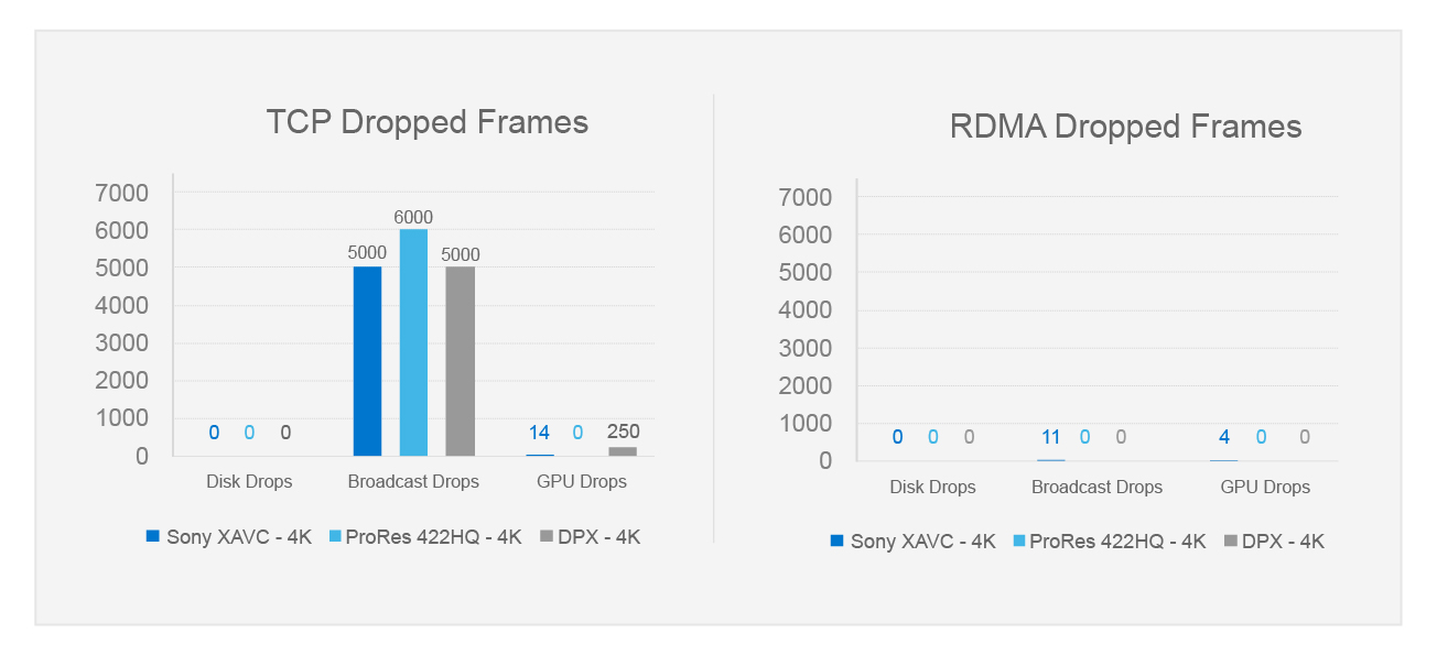
The storage is plenty fast enough. However, with the file system mounted using TCP, the broadcast output dropped thousands of frames, and the workstation could not keep up. Playing back the material over RDMA was a different story, smooth broadcast output and essentially no dropped frames at all. In this case, it was all about the CPU cycles freed up by RDMA.
NFS over RDMA is a big deal for PowerScale OneFS environments supporting the highest end playback. The twin benefits of storage performance and workstation CPU savings change what is possible with network storage. For more specifics about the storage environment, the tests run, and how to leverage NFS over RDMA, see my detailed white paper PowerScale OneFS: NFS over RDMA for Media.
Author: Gregory Shiff, Principal Solutions Architect, Media & Entertainment LinkedIn

PowerScale OneFS Release 9.3 now supports Secure Boot
Fri, 22 Oct 2021 20:50:20 -0000
|Read Time: 0 minutes
Many organizations are looking for ways to further secure systems and processes in today's complex security environments. The grim reality is that a device is typically most susceptible to loading malicious malware during its boot sequence.
With the introduction of OneFS 9.3, the UEFI Secure Boot feature is now supported on Isilon A2000 nodes. Not only does the release support the UEFI Secure Boot feature, but OneFS goes a step further by adding FreeBSD’s signature validation. Combining UEFI Secure Boot and FreeBSD’s signature validation helps protect the boot process from potential malware attacks.
The Unified Extensible Firmware Interface (UEFI) Forum standardizes and secures the boot sequence across devices with the UEFI specification. UEFI Secure Boot was introduced in UEFI 2.3.1, allowing only authorized EFI binaries to load.
FreeBSD’s veriexec function is used to perform signature validation for the boot loader and kernel. In addition, the PowerScale Secure Boot feature runs during the node’s bootup process only, using public-key cryptography to verify the signed code, to ensure that only trusted code is loaded on the node.
The Secure Boot feature does not impact cluster performance because the feature is only executed at bootup.
Pre-requisites
The OneFS Secure Boot feature is only supported on Isilon A2000 nodes at this time. The cluster must be upgraded and committed to OneFS 9.3. After the release is committed, proceed with upgrading the Node Firmware Package to 11.3 or higher.
Considerations
PowerScale nodes are not shipped with the Secure Boot feature enabled. The feature must be enabled on each node manually in a cluster. Now, a mixed cluster is supported where some nodes have the Secure Boot feature enabled, and others have it disabled.
A license is not required for the PowerScale Secure Boot feature. The Secure Boot feature can be enabled and disabled at any point, but it requires a maintenance window to reboot the node.
Configuration
You can use IPMI or the BIOS to enable the PowerScale Secure Boot feature, but disabling the feature requires using the BIOS.
For more information about the PowerScale Secure Boot feature, and detailed configuration steps, see the Dell EMC PowerScale OneFS Secure Boot white paper.
For more great information about PowerScale, see the PowerScale Info Hub at: https://infohub.delltechnologies.com/t/powerscale-isilon-1/.
Author: Aqib Kazi

Dell EMC PowerScale for Developing Autonomous Driving Vehicles

Wed, 24 Apr 2024 13:01:04 -0000
|Read Time: 0 minutes
Competition in the era of autonomy
The automotive industry is in a highly competitive transitional period where success is not about winning, it’s about survival. Once an industry of pure hardware and adrenaline, automotive design is increasingly dependent upon, and differentiated by, software. This is especially true for Advanced Driver Assistance Systems (ADAS) development, which is introducing disruptive requirements on engineering IT Infrastructure – particularly storage, where even entry level capacities are measured in petabytes.
SAE International, formerly known as the Society of Automotive Engineers, has defined different levels of automation. Most modern cars today have features that are at level 2-3. Today’s SAE level 3 ADAS projects have already outstripped legacy storage solutions, and with level 4 and 5 projects around the corner, the need for storage solutions optimized for high performance, high concurrency, and massive scalability has never been greater.

The value of data
As ADAS solutions evolve from simple collision-avoidance systems to fully autonomous vehicles, these systems will combine complex sensing, processing, and algorithmic technologies. This vehicle-generated data is a critical component to improving ADAS systems, feeding into integrated test and development cycles (or development tool chains) for these systems.
In addition to vehicular data, ADAS Test and Development systems in the next three to five years will also rely on inputs from infrastructure to support the growing scale of data movement, computing, and storing required between the vehicles, across the edge, through the cloud, and within on-premises environments. Such data will support ongoing modifications to current simulation, SiL (Software in-the-Loop), and HiL (Hardware-in-the-Loop) testing to improve the reliability of services after deployment.
The following figure illustrates the typical ADAS development life cycle for automotive OEMs and suppliers leveraging the Dell EMC PowerScale scale-out NAS as the central data lake with our Data Management Systems (DMS) for ADAS:
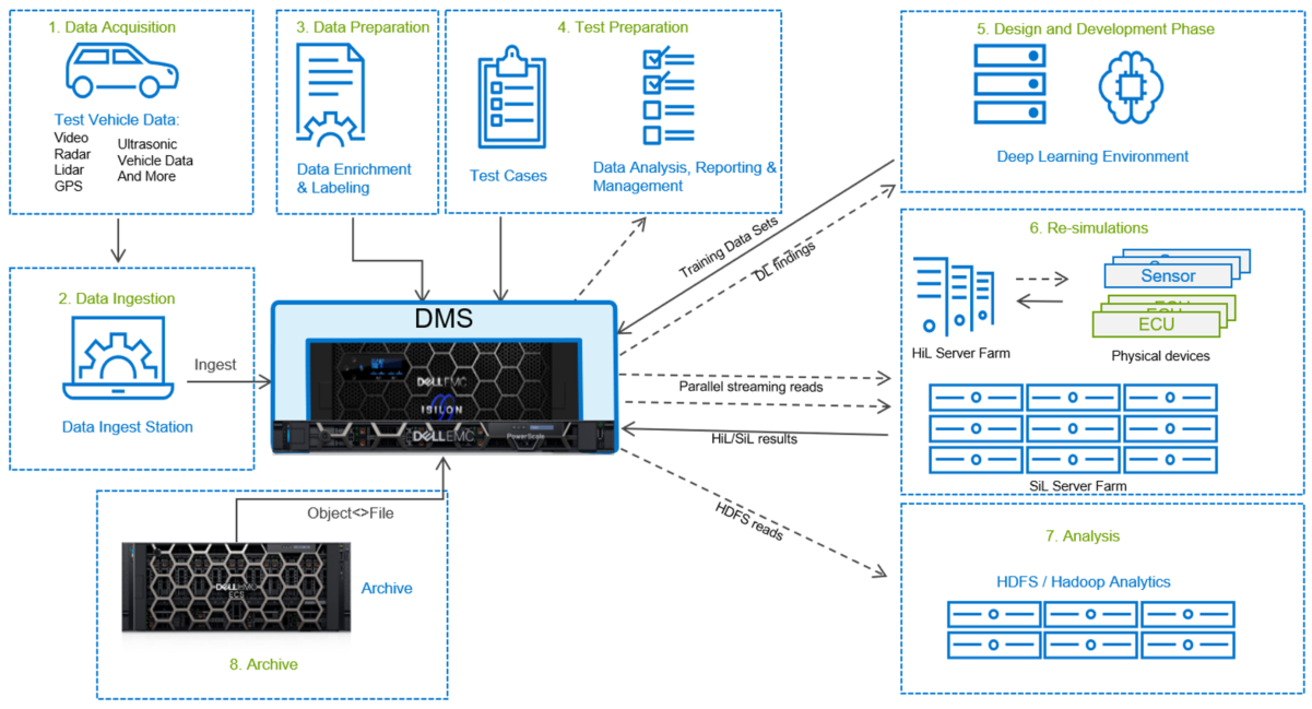
Scaling and evolving ADAS systems will require a seamless data management process and IT infrastructure that is flexible enough to handle challenges such as:
- Future-proofing ADAS simulation and architecture, to adapt to changes in vehicle sensors and other environmental data points.
- Managing data storage to comply with regulatory and privacy requirements, while addressing performance, security, and accessibility needs.
- Analyzing massive volumes of unstructured data sets, to support analytical modelling and querying of ADAS data. This requires costly and time-consuming data preparation steps, such as labeling data for analysis.
- Most of the sensor data is required to be used for quick data restoration for decades, so it has to be added to long term archives.
Ideally architected for ADAS development and certification, Dell EMC PowerScale provides the scalability, performance, parallelism, and easy to use management tools to help OEMs and Tier-1 suppliers accelerate their ADAS projects. PowerScale supports simultaneous ingest from thousands of concurrent streams from around the globe, provides simultaneous access for Model-in-the-loop (MIl), Hardware in the loop (HiL), Software in the loop (SiL) testing, Deep Learning/AI, and includes archive options to meet regulatory resimulation SLAs.
Accelerate and scale your ADAS/AD development success
The data management and computational demands underpinning the ADAS/AD (autonomous driving) test and dev environment are substantial and require solutions that can scale to accommodate complex exponentially growing ADAS/AD data sets. Essential to helping ADAS/AD development teams unlock the data and create value is a high performance and high-capacity platform that can provide the following:
- A consistent, high throughput solution to ingest data from test vehicles while simultaneously delivering the test data into hundreds to thousands of concurrent streams to MiL/SiL/HiL servers, test stands, and even deep learning training. It must also scale performance near-linearly, so performance isn’t degraded as capacity is added—critical for ADAS development where sensor data ingest rates of 2 PB+ per week are becoming common.
- A high performance and predictable storage solution that will scale and manage ADAS/AD data sets and workloads as they grow centrally and regionally. Essential elements of the platform include an expandable single namespace, eliminating data silos by consolidating all globally collected ADAS/AD data; automated plug and play hardware detection and expansion that won’t disrupt ongoing projects; automated policy-based tiering to reduce file server sprawl and performance bottlenecks; and file-object orchestration and encryption that will allow data movement between high performance network-attached storage and lower-cost private and public cloud options.
- Distributed deep learning frameworks are core to unlocking data capital and foundational to ADAS and AD development. Because deep learning models are very complex and large, developers can benefit from using a deep learning framework — an interface, library, or tool that allows them to leverage deep learning easily and quickly, without requiring in-depth understanding of the underlying algorithms. These frameworks provide a clear and concise way for defining models using a collection of pre-built and pre-optimized components. Essential characteristics of well-designed deep learning frameworks, such as Tensorflow, Keras, PyTorch, and Caffe, including optimization for GPU performance, easy to understand code, extensive community support, process parallelization to reduce computation cycles, and automatically computed gradients.
- An optimized and scalable accelerator-based platform that has the capacity and ability to run AI in place as well as deep learning (training) and MiL/HiL/SiL workloads. Engineers and data scientists continuously manage massive data sets and compute-intensive workloads to run their ADAS/AD test and dev operations across departments and around the globe. A large capacity and distributed GPU-based compute and storage infrastructure gives development teams the ability to rapidly build, train, and deploy test cases and AI models, predictive analytics, simulations, and re-simulations.
Top reasons to choose Dell EMC PowerScale for ADAS/AD
Small footprint, big performance for the edge
PowerScale F200 and F600 are new small-scale all flash nodes offering high throughput for small deployment scenarios such as on-prem data caching, required when streaming data from public cloud for Hardware-in-the-Loop (HiL) testing, or regional sensor data ingest stations. These low-cost nodes can be added to existing PowerScale/Isilon clusters - making it simple to expand with high performance.
Massive scalability for the data center
AD/ADAS datasets are growing exponentially, with requirements ranging from petabytes to exabytes of data. Dell EMC PowerScale scales as your needs grow so you can invest in infrastructure that fits your current ADAS storage requirements without overbuying performance or capacity. Scalable to tens of petabytes (PB) in a single cluster, PowerScale offers truly scalable performance and an ever-expanding single namespace that eliminates data silos by consolidating all globally collected ADAS/AD data. Tools like CloudPools take this scalability into the exabyte (EB) range, allowing data to be moved between the high-performance NAS and multiple lower-cost storage options like Dell EMC ECS object storage.
Throughput to accelerate ADAS/AD time-to-market
PowerScale delivers the consistent, high throughput required to concurrently deliver test data into hundreds to thousands of MiL/SiL/HiL servers, test stands, and Deep Learning networks simultaneously. Multiple node types can be deployed within a single cluster, so you can deploy the storage infrastructure that meets your exact needs from high performance all-flash for AI to low-cost SATA for long term archiving. PowerScale also scales performance linearly as additional capacity is added to the cluster – critical for ADAS development where sensor data ingest rates of 2PB+ per week are becoming common.
Maintain sensor data compliance
Most ADAS projects face strict requirements for data compliance and retention, including data privacy, physical media security, and even service level agreements (SLAs) that dictate retention of petabytes to exabytes of data for decades, with as little as a few days’ notice for full data restoration. Policy-based SmartPools and CloudPools alleviate SLA challenges by automatically tiering data to lower cost storage for long-term retention, and to higher-performance storage for revalidation. Keeping sensor test and verification data within easy reach avoids the “mad-dash” to restore large data sets from archive in the case of a defect, safety recall, or audit. The necessary data remains directly accessible within the PowerScale and ECS storage infrastructure. To protect sensitive sensor data, CloudPools fully encrypts data before offloading it to the target, which can include your own on-premises Dell EMC ECS object storage and third-party providers.
Debug designs faster
The PowerScale OneFS operating system includes native multi-protocol support so workflows can quickly access data stored on a single cluster, eliminating the need for additional data movement. OneFS offers simultaneous access to all PowerScale nodes for a mix of AD/ADAS workloads from data ingest, MiL, SiL, and HiL testing, to Deep Learning using TensorFlow. OneFS also supports data enrichment with access to on-line databases for weather, GPS location queries, road surface types, and so on. In-place analytics for sensor data and simulation results eliminates the time and expense of moving large data sets between file and other storage solutions typically required. Multi-protocol support includes NFS, SMB, HDFS, SWIFT, HTTP, REST, and others. OneFS also supports S3, an essential protocol for cloud native applications. PowerScale easily integrates with the Dell EMC streaming data platform, offering insights on real-time and historical sensor data.

Dell complete solutions: a complete autonomous driving data lake reference architecture
Our new Dell Autonomous Drive ecosystem supports the most important steps in the ADAS/AD data process. Developed in conjunction with leading industry and technology partners, Dell Autonomous Drive combines Dell Technologies and partner infrastructure, software, and services to offer a complete end-to-end toolchain.
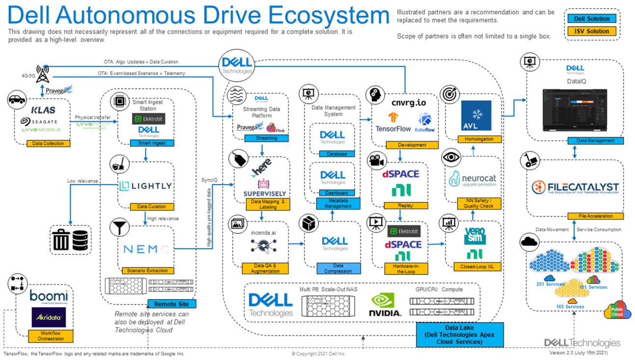
For more information:
- See the blog What DevOps for AD/ADAS Looks Like.
- See our white paper Dell Technologies Automotive Solutions.
- For regularly updated automotive industry events and content, please bookmark https://Dell.to/automotive-events.
- Stay tuned for future blogs!
Author: Frances Weiyi Hu LinkedIn

Announcing Drain-based Nondisruptive Upgrades (NDUs)
Thu, 16 Sep 2021 17:43:39 -0000
|Read Time: 0 minutes
During an NDU workflow, nodes are rebooted or the protocol service must be stopped temporarily. Up until now, this has required a disruption for the clients who are connected to the rebooting node.
A drain-based NDU provides a mechanism by which nodes are prevented from rebooting or restarting protocol services until all SMB clients have disconnected from the node. Because a single SMB client that does not disconnect can cause the upgrade to be delayed indefinitely, the user is now provided with options to reboot the node despite persisting clients.
A drain-based upgrade supports the following scenarios and is available for WebUI, CLI, and PAPI:
- SMB protocol
- OneFS upgrades
- Firmware upgrades
- Cluster reboots
- Combined upgrades (OneFS and firmware)
A drain-based upgrade is built upon a parallel upgrade workflow, introduced in OneFS 8.2.2.0, that offers parallel node upgrade and reboot activity across node neighborhoods. It upgrades at most one node per neighborhood at any time. By doing that, it can shorten upgrade time and ensure that the end-user can continue to have access to their data. The more node neighborhoods within a cluster, the more parallel activity can occur.
Figure 1 shows how it works. In this example, there are two neighborhoods in a 6-node PowerScale cluster. Nodes 1 thru 3 belong to Neighborhood 1; Nodes 4 thru 6 belong to Neighborhood 2.
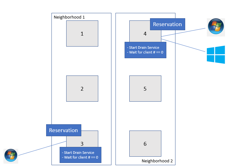
Figure 1: An example of Drain based NDU
You can use the following command to identify the correlation between your PowerScale nodes and neighborhoods (failure domains):
# sysctl efs.lin.lock.initiator.coordinator_weights
Once the drain-based upgrade is started, at most one node from each neighborhood will get the reservation that allows the nodes to upgrade simultaneously. OneFS will not reboot these nodes until the number of SMB clients is “0”. In this example, Node 3 and Node 4 get the reservation for upgrading at the same time. However, there is one SMB connection for Node 3 and two SMB connections for Node 4. They will not be able to reboot until the SMB connections get to “0”. At this stage, there are three options:
- Wait - Wait until the number of SMB connections reaches “0” or it hits the drain timeout value. The drain timeout value is the configurable parameter for each upgrade process. It is the maximum waiting period. If drain timeout is set to “0”, it means wait forever.
- Delay drain - Add the node to the delay list to delay client draining. The upgrade process will continue on another node in this neighborhood. After all the non-delayed nodes are upgraded, OneFS will return to the node in the delay list.
- Skip drain - Stop waiting for clients to migrate away from the draining node and reboot immediately.
To run the drain-based NDU, follow these steps:
1. In the OneFS CLI, run the following command to perform the drain-based upgrade. In this example, we have set the drain timeout value to 60 minutes and the alert timeout value to 45 minutes. This means if there is still some connection after 45 minutes, a CELOG notification will be triggered to the administrator.
# isi upgrade start --parallel --skip-optional --install-image-path=/ifs /data/<installation-file-name> --drain-timeout=60m --alert-timeout=45m
The draining service is now waiting for further action (wait, delay, or skip) from the end user, when it detects that there is an active SMB connection between client and PowerScale.
2. In the OneFS WebUI, navigate to Upgrade under Cluster management. In this window you will see the node waiting for draining clients. You can either specify Skip or Delay. In this case, Skip is selected as shown in Figure 2. In the prompt window, click the Skip button to skip draining.
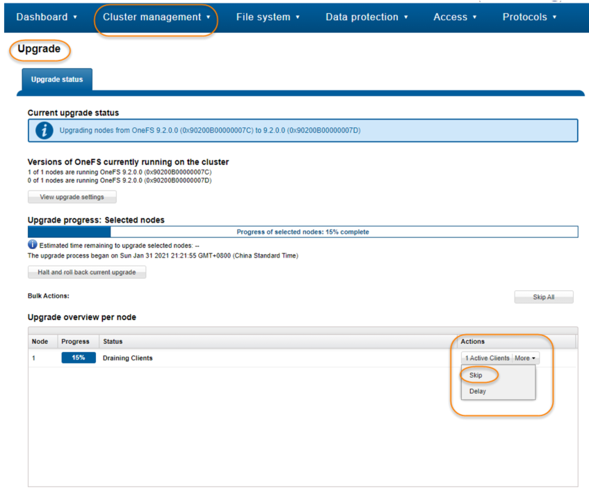
Figure 2. Skip the draining clients
Conclusion
Drain-based NDU can minimize the business impact during the OneFS upgrade process by allowing you to control how and when clients disconnect from the PowerScale cluster. This new feature can significantly improve the user experience and business continuity.
Author: Vincent Shen

Accelerating your Network File System (NFS) Workloads with RDMA
Wed, 15 Sep 2021 13:19:26 -0000
|Read Time: 0 minutes
The NFS protocol is widely used in datacenters by NAS storage nowadays. It was originally designed for storing and managing data centrally, then sharing data across networks. As technologies evolved, NFS has been used for critical production workloads by many organizations.
NFS is usually implemented over TCP to transfer data. With the emergence of higher speed Ethernet and heavier application workloads running in datacenters, the speed of transferring the ever-increasing volume of data is critical to organizations. The industry has been pursuing new ways to improve NFS protocol performance and to adapt to emerging application workloads. This has made possible using NFS over Remote Direct Memory Access (RDMA).
RDMA enables accessing memory data on a remote machine without passing the data through the CPUs on the system. RDMA therefore enables data to be transferred between storage and clients with higher throughput and lower CPU usage. NFS over RDMA, as defined in RFC8267, uses the advantages of RDMA. Starting with OneFS 9.2.0, OneFS supports NFSv3 over RDMA based on the ROCEv2 (also known as Routable RoCE or RRoCE) network protocol.
To evaluate the improvements and advantages of NFSv3 over RDMA, as compared to NFSv3 over TCP, we ran some FIO sequential read tests, and observed the throughput and CPU usage under different thread counts. The following figure shows the test environment topology and resource configuration.
| Cluster nodes | Clients |
Quantity | 48-node cluster | 10 |
OS Version | OneFS 9.2.1.0 | CentOS Linux release 8.3.2011 |
Model | F600 | Dell PowerEdge C4140 clients |
Network device | 2 * MT28800 Family [ConnectX-5 Ex] * 100GE | 2 * MT28908 Family [ConnectX-6] * 100GE |
The following chart shows the throughput comparison for RDMA vs. TCP. We found that NFSv3 over RDMA delivers higher throughput than NFSv3 over TCP. (Note: Because 10 test clients cannot overload a 48-node F600 cluster, the throughput number is only used for RDMA and TCP comparison and does not represent the maximum cluster performance.)
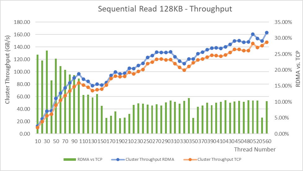
The following chart shows the clients’ CPU usage comparison for RDMA vs. TCP. We found that clients consume fewer CPU resources when using NFSv3 over RDMA.
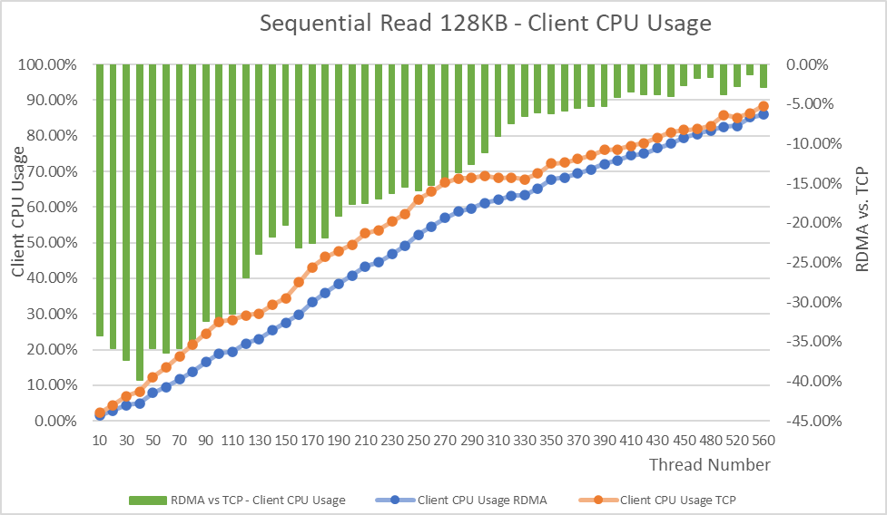
Conclusion
The NFSv3 over RDMA performance improvement does vary as the client thread number increases, as compared to NFSv3 over TCP. Overall, NFSv3 over RDMA delivers higher throughput while providing significant reduction of clients’ CPU overhead. Sequential workloads and CPU-intensive workloads can therefore benefit from using NFSv3 over RDMA on OneFS.
Author: Lieven Lin, LinkedIn

Unstructured Data Quick Tips - OneFS Protection Overhead
Wed, 08 Sep 2021 20:40:29 -0000
|Read Time: 0 minutes
There have been several questions from the field recently about how to calculate the OneFS storage protection overhead for different cluster sizes and protection levels. But first, a quick overview of the fundamentals…
OneFS supports several protection schemes. These include the ubiquitous +2d:1n, which protects against two drive failures or one node failure. The best practice is to use the recommended protection level for a particular cluster configuration. This recommended level of protection is clearly marked as ‘suggested’ in the OneFS WebUI storage pools configuration pages and is typically configured by default. For all current Gen6 hardware configurations, the recommended protection level is “+2d:1n”.
The hybrid protection schemes are particularly useful for Gen6 chassis high-density node configurations, where the probability of multiple drives failing far surpasses that of an entire node failure. In the unlikely event that multiple devices have simultaneously failed, such that the file is “beyond its protection level”, OneFS will re-protect everything possible and report errors on the individual files affected to the cluster’s logs.
OneFS also provides a variety of mirroring options ranging from 2x to 8x, allowing from two to eight mirrors of the specified content. Metadata, for example, is mirrored at one level above FEC (forward error correction) by default. For example, if a file is protected at +2n, its associated metadata object will be 3x mirrored.
The full range of OneFS protection levels are as follows:
Protection Level | Description |
+1n | Tolerate failure of 1 drive OR 1 node |
+2d:1n | Tolerate failure of 2 drives OR 1 node |
+2n | Tolerate failure of 2 drives OR 2 nodes |
+3d:1n | Tolerate failure of 3 drives OR 1 node |
+3d:1n1d | Tolerate failure of 3 drives OR 1 node AND 1 drive |
+3n | Tolerate failure of 3 drives or 3 nodes |
+4d:1n | Tolerate failure of 4 drives or 1 node |
+4d:2n | Tolerate failure of 4 drives or 2 nodes |
+4n | Tolerate failure of 4 nodes |
2x to 8x | Mirrored over 2 to 8 nodes, depending on configuration |
The charts below show the ‘ideal’ protection overhead across the range of node counts and OneFS protection levels (noted within brackets). For each field in this chart, the overhead percentage is calculated by dividing the sum of the two numbers by the number on the right.
x+y => y/(x+y)
So, for a 5-node cluster protected at +2d:1n, OneFS uses an 8+2 layout – hence an ‘ideal’ overhead of 20%.
8+2 => 2/(8+2) = 20%
Number of nodes | [+1n] | [+2d:1n] | [+2n] | [+3d:1n] | [+3d:1n1d] | [+3n] | [+4d:1n] | [+4d:2n] | [+4n] |
3 | 2 +1 (33%) | 4 + 2 (33%) | — | 6 + 3 (33%) | 3 + 3 (50%) | — | 8 + 4 (33%) | — | — |
4 | 3 +1 (25%) | 6 + 2 (25%) | — | 9 + 3 (25%) | 5 + 3 (38%) | — | 12 + 4 (25%) | 4 + 4 (50%) | — |
5 | 4 +1 (20%) | 8+ 2 (20%) | 3 + 2 (40%) | 12 + 3 (20%) | 7 + 3 (30%) | — | 16 + 4 (20%) | 6 + 4 (40%) | — |
6 | 5 +1 (17%) | 10 + 2 (17%) | 4 + 2 (33%) | 15 + 3 (17%) | 9 + 3 (25%) | — | 16 + 4 (20%) | 8 + 4 (33%) | — |
The ‘x+y’ numbers in each field in the table also represent how files are striped across a cluster for each node count and protection level.
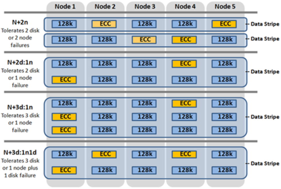
Take for example, with +2n protection on a 6-node cluster, OneFS will write a stripe across all 6 nodes, and use two of the stripe units for parity/ECC and four for data.
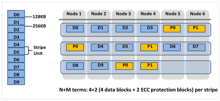
In general, for FEC protected data the OneFS protection overhead will look something like below.
Note that the protection overhead % (in brackets) is a very rough guide and will vary across different datasets, depending on quantities of small files, and so on.
Number of nodes | [+1n] | [+2d:1n] | [+2n] | [+3d:1n] | [+3d:1n1d] | [+3n] | [+4d:1n] | [+4d:2n] | [+4n] |
3 | 2 +1 (33%) | 4 + 2 (33%) | — | 6 + 3 (33%) | 3 + 3 (50%) | — | 8 + 4 (33%) | — | — |
4 | 3 +1 (25%) | 6 + 2 (25%) | — | 9 + 3 (25%) | 5 + 3 (38%) | — | 12 + 4 (25%) | 4 + 4 (50%) | — |
5 | 4 +1 (20%) | 8 + 2 (20%) | 3 + 2 (40%) | 12 + 3 (20%) | 7 + 3 (30%) | — | 16 + 4 (20%) | 6 + 4 (40%) | — |
6 | 5 +1 (17%) | 10 + 2 (17%) | 4 + 2 (33%) | 15 + 3 (17%) | 9 + 3 (25%) | — | 16 + 4 (20%) | 8 + 4 (33%) | — |
7 | 6 +1 (14%) | 12 + 2 (14%) | 5 + 2 (29%) | 15 + 3 (17%) | 11 + 3 (21%) | 4 + 3 (43%) | 16 + 4 (20%) | 10 + 4 (29%) | — |
8 | 7 +1 (13%) | 14 + 2 (12.5%) | 6 + 2 (25%) | 15 + 3 (17%) | 13 + 3 (19%) | 5 + 3 (38%) | 16 + 4 (20%) | 12 + 4 (25%) | — |
9 | 8 +1 (11%) | 16 + 2 (11%) | 7 + 2 (22%) | 15 + 3 (17%) | 15 + 3 (17%) | 6 + 3 (33%) | 16 + 4 (20%) | 14 + 4 (22%) | 5 + 4 (44%) |
10 | 9 +1 (10%) | 16 + 2 (11%) | 8 + 2 (20%) | 15 + 3 (17%) | 15 + 3 (17%) | 7 + 3 (30%) | 16 + 4 (20%) | 16 + 4 (20%) | 6 + 4 (40%) |
12 | 11 +1 (8%) | 16 + 2 (11%) | 10 + 2 (17%) | 15 + 3 (17%) | 15 + 3 (17%) | 9 + 3 (25%) | 16 + 4 (20%) | 16 + 4 (20%) | 6 + 4 (40%) |
14 | 13 +1 (7%) | 16 + 2 (11%) | 12 + 2 (14%) | 15 + 3 (17%) | 15 + 3 (17%) | 11 + 3 (21%) | 16 + 4 (20%) | 16 + 4 (20%) | 10 + 4 (29%) |
16 | 15 +1 (6%) | 16 + 2 (11%) | 14 + 2 (13%) | 15 + 3 (17%) | 15 + 3 (17%) | 13 + 3 (19%) | 16 + 4 (20%) | 16 + 4 (20%) | 12 + 4 (25%) |
18 | 16 +1 (6%) | 16 + 2 (11%) | 16 + 2 (11%) | 15 + 3 (17%) | 15 + 3 (17%) | 15 + 3 (17%) | 16 + 4 (20%) | 16 + 4 (20%) | 14 + 4 (22%) |
20 | 16 +1 (6%) | 16 + 2 (11%) | 16 + 2 (11%) | 16 + 3 (16%) | 16 + 3 (16%) | 16 + 3 (16%) | 16 + 4 (20%) | 16 + 4 (20%) | 14 + 4 (22%) |
30 | 16 +1 (6%) | 16 + 2 (11%) | 16 + 2 (11%) | 16 + 3 (16%) | 16 + 3 (16%) | 16 + 3 (16%) | 16 + 4 (20%) | 16 + 4 (20%) | 14 + 4 (22%) |
The protection level of the file is how the system decides to layout the file. A file may have multiple protection levels temporarily (because the file is being restriped) or permanently (because of a heterogeneous cluster). The protection level is specified as “n + m/b@r” in its full form. In the case where b, r, or both equal 1, it may be shortened to get “n + m/b”, “n + m@r”, or “n + m”.
Layout Attribute | Description |
N | Number of data drives in a stripe. |
+m | Number of FEC drives in a stripe. |
/b | Number of drives per stripe allowed on one node. |
@r | Number of drives per node to include in a file. |
The OneFS protection definition in terms of node and/or drive failures has the advantage of configuration simplicity. However, it does mask some of the subtlety of the interaction between stripe width and drive spread, as represented by the n+m/b notation displayed by the ‘isi get’ CLI command. For example:
# isi get README.txt POLICY LEVEL PERFORMANCE COAL FILE default 6+2/2 concurrency on README.txt
In particular, both +3/3 and +3/2 allow for a single node failure or three drive failures and appear the same according to the web terminology. Despite this, they do in fact have different characteristics. +3/2 allows for the failure of any one node in combination with the failure of a single drive on any other node, which +3/3 does not. +3/3, on the other hand, allows for potentially better space efficiency and performance because up to three drives per node can be used, rather than the 2 allowed under +3/2.
Another factor to keep in mind is OneFS neighborhoods. A neighborhood is a fault domain within a node pool. The purpose of neighborhoods is to improve reliability in general – and guard against data unavailability from the accidental removal of Gen6 drive sleds. For self-contained nodes like the PowerScale F200, OneFS has an ideal size of 20 nodes per node pool, and a maximum size of 39 nodes. On the addition of the 40th node, the nodes split into two neighborhoods of 20 nodes.
With the Gen6 platform, the ideal size of a neighborhood changes from 20 to 10 nodes. It also means that a Gen6 nodes pool will never reach the large stripe width (for example 16+3) since the pool will have already split.
This 10-node ideal neighborhood size helps protect the Gen6 architecture against simultaneous node-pair journal failures and full chassis failures. Partner nodes are nodes whose journals are mirrored. Rather than each node storing its journal in NVRAM as in the PowerScale platforms, the Gen6 nodes’ journals are stored on SSDs – and every journal has a mirror copy on another node. The node that contains the mirrored journal is referred to as the partner node.
There are several reliability benefits gained from the changes to the journal. For example, SSDs are more persistent and reliable than NVRAM, which requires a charged battery to retain state. Also, with the mirrored journal, both journal drives have to die before a journal is considered lost. As such, unless both of the mirrored journal drives fail, both of the partner nodes can function as normal.
With partner node protection, where possible, nodes will be placed in different neighborhoods – and hence different failure domains. Partner node protection is possible once the cluster reaches five full chassis (20 nodes) when, after the first neighborhood split, OneFS places partner nodes in different neighborhoods:
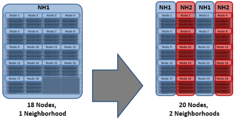
Partner node protection increases reliability because if both nodes go down, they are in different failure domains, so their failure domains only suffer the loss of a single node.
With chassis protection, when possible, each of the four nodes within a chassis will be placed in a separate neighborhood. Chassis protection becomes possible at 40 nodes, as the neighborhood split at 40 nodes enables every node in a chassis to be placed in a different neighborhood. As such, when a 38 node Gen6 cluster is expanded to 40 nodes, the two existing neighborhoods will be split into four 10-node neighborhoods:
Chassis protection ensures that if an entire chassis failed, each failure domain would only lose one node.
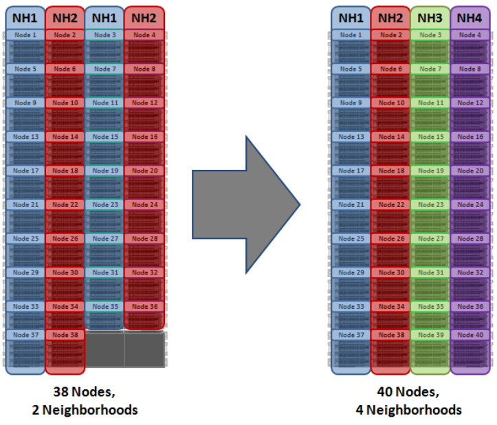
Author: Nick Trimbee