


OneFS Hardware Platform Considerations

A key decision for performance, particularly in a large cluster environment, is the type and quantity of nodes deployed. Heterogeneous clusters can be architected with a wide variety of node styles and capacities, to meet the needs of a varied data set and a wide spectrum of workloads. These node styles encompass several hardware generations, and fall loosely into three main categories or tiers. While heterogeneous clusters can easily include many hardware classes and configurations, the best practice of simplicity for building clusters holds true here too.
Consider the physical cluster layout and environmental factors, particularly when designing and planning a large cluster installation. These factors include:
- Redundant power supply
- Airflow and cooling
- Rackspace requirements
- Floor tile weight constraints
- Networking requirements
- Cabling distance limitations
The following table details the physical dimensions, weight, power draw, and thermal properties for the range of PowerScale F-series all-flash nodes:
Model | Tier | Height | Width | Depth | RU | Weight | Max Watts | Watts | Max BTU | Normal BTU |
F900 | All-flash NVMe performance | 2U | 17.8 IN / | 31.8 IN / 85.9 cm | 2RU | 73 lbs | 1297 | 859 | 4425 | 2931 |
F600 | All-flash NVMe Performance | 1U (1.75IN) | 17.8 IN / | 31.8 IN / 85.9 cm | 1RU | 43 lbs | 467 | 718 | 2450 | 1594 |
F200 | All-flash | 1U (1.75IN) | 17.8 IN / | 31.8 IN / 85.9 cm | 1RU | 47 lbs | 395 | 239 | 1346 | 816 |
Note that the table above represents individual nodes. A minimum of three similar nodes are required for a node pool.
Similarly, the following table details the physical dimensions, weight, power draw, and thermal properties for the range of PowerScale chassis-based platforms:
Model | Tier | Height | Width | Depth | RU | Weight | Max Watts | Watts | Max BTU | Normal BTU |
F800/ | All-flash performance | 4U (4×1.75IN) | 17.6 IN / 45 cm | 35 IN / | 4RU | 169 lbs (77 kg) | 1764 | 1300 | 6019 | 4436 |
H700 |
Hybrid/Utility | 4U (4×1.75IN) | 17.6 IN / 45 cm | 35 IN / | 4RU | 261lbs (100 kg) | 1920 | 1528 | 6551 | 5214 |
H7000 |
Hybrid/Utility | 4U (4×1.75IN) | 17.6 IN / 45 cm | 39 IN / | 4RU | 312 lbs (129 kg) | 2080 | 1688 | 7087 | 5760 |
H600 |
Hybrid/Utility | 4U (4×1.75IN) | 17.6 IN / 45 cm | 35 IN / | 4RU | 213 lbs (97 kg) | 1990 | 1704 | 6790 | 5816 |
H5600 |
Hybrid/Utility | 4U (4×1.75IN) | 17.6 IN / 45 cm | 39 IN / | 4RU | 285 lbs (129 kg) | 1906 | 1312 | 6504 | 4476 |
H500 |
Hybrid/Utility | 4U (4×1.75IN) | 17.6 IN / 45 cm | 35 IN / | 4RU | 248 lbs (112 kg) | 1906 | 1312 | 6504 | 4476 |
H400 |
Hybrid/Utility | 4U (4×1.75IN) | 17.6 IN / 45 cm | 35 IN / | 4RU | 242 lbs (110 kg) | 1558 | 1112 | 5316 | 3788 |
A300 |
Archive | 4U (4×1.75IN) | 17.6 IN / 45 cm | 35 IN / | 4RU | 252 lbs (100 kg) | 1460 | 1070 | 4982 | 3651 |
A3000 |
Archive | 4U (4×1.75IN) | 17.6 IN / 45 cm | 39 IN / | 4RU | 303 lbs (129 kg) | 1620 | 1230 | 5528 | 4197 |
A200 |
Archive | 4U (4×1.75IN) | 17.6 IN / 45 cm | 35 IN / | 4RU | 219 lbs (100 kg) | 1460 | 1052 | 4982 | 3584 |
A2000 |
Archive | 4U (4×1.75IN) | 17.6 IN / 45 cm | 39 IN / | 4RU | 285 lbs (129 kg) | 1520 | 1110 | 5186 | 3788 |
Note that this table represents 4RU chassis, each of which contains four PowerScale platform nodes (the minimum node pool size).
The following figure shows the locations of both the front-end (ext-1 & ext-2) and back-end (int-1 & int-2) network interfaces on the PowerScale stand-alone F-series and chassis-based nodes:
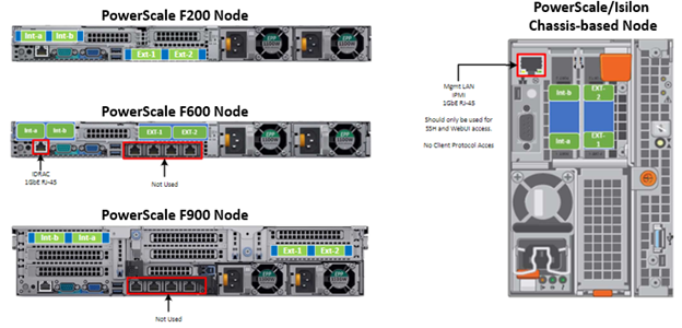
A PowerScale cluster’s back-end network is analogous to a distributed systems bus. Each node has two back-end interfaces for redundancy that run in an active/passive configuration (int-1 and int-2 above). The primary interface is connected to the primary switch; the secondary interface is connected to a separate switch.
For nodes using 40/100 Gb or 25/10 Gb Ethernet or InfiniBand connected with multimode fiber, the maximum cable length is 150 meters. This allows a cluster to span multiple rack rows, floors, and even buildings, if necessary. While this can solve floor space challenges, in order to perform any physical administration activity on nodes, you must know where the equipment is located.
The following table shows the various PowerScale node types and their respective back-end network support. While Ethernet is the preferred medium – particularly for large PowerScale clusters – InfiniBand is also supported for compatibility with legacy Isilon clusters.
Node Models | Details |
F200, F600, F900 | F200: nodes support a 10 GbE or 25 GbE connection to the access switch using the same NIC. A breakout cable can connect up to four nodes to a single switch port.
F600: nodes support a 40 GbE or 100 GbE connection to the access switch using the same NIC.
F900: nodes support a 40 GbE or 100 GbE connection to the access switch using the same NIC. |
H700, H7000, A300, A3000 | Supports 40 GbE or 100 GbE connection to the access switch using the same NIC.
OR
Supports 25 GbE or 10 GbE connection to the leaf using the same NIC. A breakout cable can connect a 40 GbE switch port to four 10 GbE nodes or a 100 GbE switch port to four 25 GbE nodes. |
F810, F800, H600, H500, H5600 | Performance nodes support a 40 GbE connection to the access switch. |
A200, A2000, H400 | Archive nodes support a 10GbE connection to the access switch using a breakout cable. A breakout cable can connect a 40 GbE switch port to four 10 GbE nodes or a 100 GbE switch port to four 10 GbE nodes. |
Currently only Dell Technologies approved switches are supported for back-end Ethernet and IB cluster interconnection. These include:
Switch | Port | Port | Height | Role | Notes |
Dell S4112 | 24 | 10GbE | ½ | ToR | 10 GbE only. |
Dell 4148 | 48 | 10GbE | 1 | ToR | 10 GbE only. |
Dell S5232 | 32 | 100GbE | 1 | Leaf or Spine | Supports 4x10GbE or 4x25GbE breakout cables.
Total of 124 10GbE or 25GbE nodes as top-of-rack back-end switch.
Port 32 does not support breakout. |
Dell Z9100 | 32 | 100GbE | 1 | Leaf or Spine | Supports 4x10GbE or 4x25GbE breakout cables.
Total of 128 10GbE or 25GbE nodes as top-of-rack back-end switch. |
Dell Z9264 | 64 | 100GbE | 2 | Leaf or Spine | Supports 4x10GbE or 4x25GbE breakout cables.
Total of 128 10GbE or 25GbE nodes as top-of-rack back-end switch. |
Arista 7304 | 128 | 40GbE | 8 | Enterprise core | 40GbE or 10GbE line cards. |
Arista 7308 | 256 | 40GbE | 13 | Enterprise/ large cluster | 40GbE or 10GbE line cards. |
Mellanox Neptune MSX6790 | 36 | QDR | 1 | IB fabric | 32Gb/s quad data rate InfiniBand. |
Be aware that the use of patch panels is not supported for PowerScale cluster back-end connections, regardless of overall cable lengths. All connections must be a single link, single cable directly between the node and back-end switch. Also, Ethernet and InfiniBand switches must not be reconfigured or used for any traffic beyond a single cluster.
Support for leaf spine back-end Ethernet network topologies was first introduced in OneFS 8.2. In a leaf-spine network switch architecture, the PowerScale nodes connect to leaf switches at the access, or leaf, layer of the network. At the next level, the aggregation and core network layers are condensed into a single spine layer. Each leaf switch connects to each spine switch to ensure that all leaf switches are no more than one hop away from one another. For example:
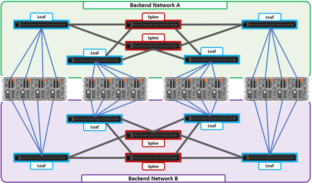
Leaf-to-spine switch connections require even distribution, to ensure the same number of spine connections from each leaf switch. This helps minimize latency and reduces the likelihood of bottlenecks in the back-end network. By design, a leaf spine network architecture is both highly scalable and redundant.
Leaf spine network deployments can have a minimum of two leaf switches and one spine switch. For small to medium clusters in a single rack, the back-end network typically uses two redundant top-of-rack (ToR) switches, rather than implementing a more complex leaf-spine topology.
Author: Nick Trimbee