OneFS Caching Hierarchy
Tue, 22 Mar 2022 20:05:56 -0000
|Read Time: 0 minutes
Caching occurs in OneFS at multiple levels, and for a variety of types of data. For this discussion we’ll concentrate on the caching of file system structures in main memory and on SSD.
OneFS’ caching infrastructure design is based on aggregating each individual node’s cache into one cluster wide, globally accessible pool of memory. This is done by using an efficient messaging system, which allows all the nodes’ memory caches to be available to each and every node in the cluster.
For remote memory access, OneFS uses the Sockets Direct Protocol (SDP) over an Ethernet or Infiniband (IB) backend interconnect on the cluster. SDP provides an efficient, socket-like interface between nodes which, by using a switched star topology, ensures that remote memory addresses are only ever one hop away. While not as fast as local memory, remote memory access is still very fast due to the low latency of the backend network.
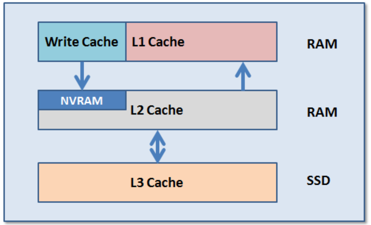
OneFS uses up to three levels of read cache, plus an NVRAM-backed write cache, or write coalescer. The first two types of read cache, level 1 (L1) and level 2 (L2), are memory (RAM) based, and analogous to the cache used in CPUs. These two cache layers are present in all PowerScale storage nodes. An optional third tier of read cache, called SmartFlash, or Level 3 cache (L3), is also configurable on nodes that contain solid state drives (SSDs). L3 cache is an eviction cache that is populated by L2 cache blocks as they are aged out from memory.
The OneFS caching subsystem is coherent across the cluster. This means that if the same content exists in the private caches of multiple nodes, this cached data is consistent across all instances. For example, consider the following scenario:
- Node 2 and Node 4 each have a copy of data located at an address in shared cache.
- Node 4, in response to a write request, invalidates node 2’s copy.
- Node 4 then updates the value.
- Node 2 must re-read the data from shared cache to get the updated value.
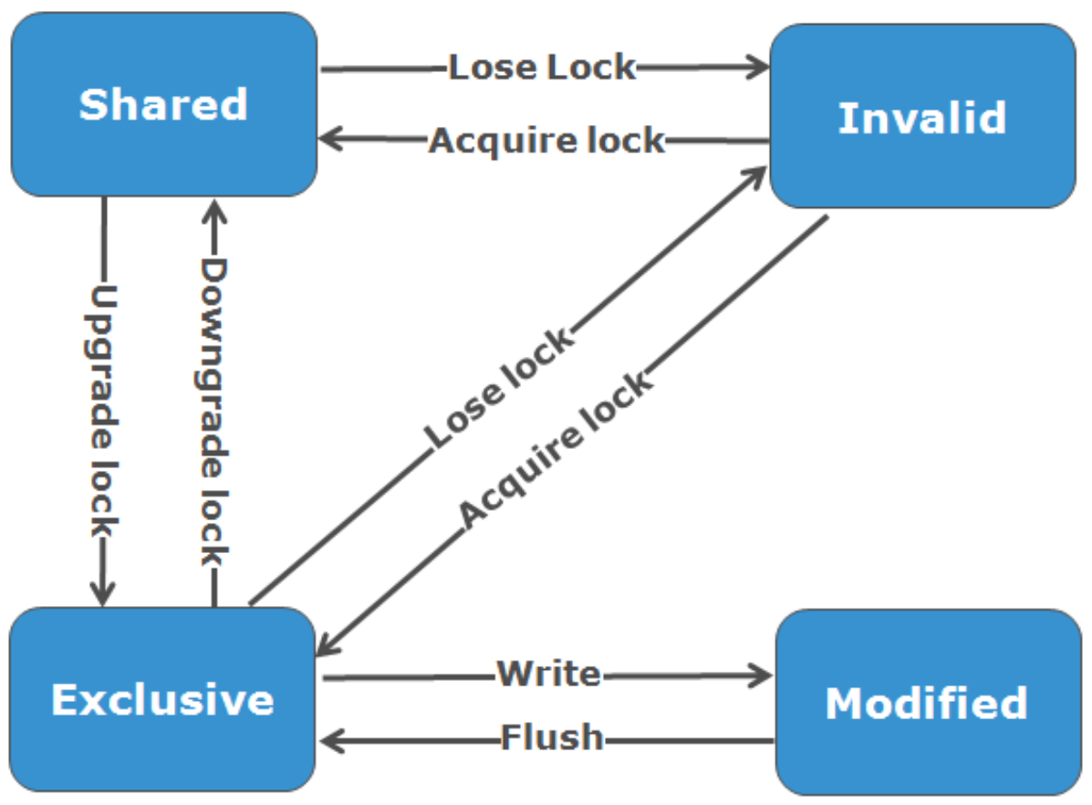
OneFS uses the MESI Protocol to maintain cache coherency, implementing an “invalidate-on-write” policy to ensure that all data is consistent across the entire shared cache. The various states that in-cache data can take are:
M – Modified: The data exists only in local cache, and has been changed from the value in shared cache. Modified data is referred to as ‘dirty’.
E – Exclusive: The data exists only in local cache, but matches what is in shared cache. This data referred to as ‘clean’.
S – Shared: The data in local cache may also be in other local caches in the cluster.
I – Invalid: A lock (exclusive or shared) has been lost on the data.
L1 cache, or front-end cache, is memory that is nearest to the protocol layers (such as NFS, SMB, and so on) used by clients, or initiators, connected to that node. The main task of L1 is to prefetch data from remote nodes. Data is pre-fetched per file, and this is optimized to reduce the latency associated with the nodes’ IB back-end network. Because the IB interconnect latency is relatively small, the size of L1 cache, and the typical amount of data stored per request, is less than L2 cache.
L1 is also known as remote cache because it contains data retrieved from other nodes in the cluster. It is coherent across the cluster, but is used only by the node on which it resides, and is not accessible by other nodes. Data in L1 cache on storage nodes is aggressively discarded after it is used. L1 cache uses file-based addressing, in which data is accessed by means of an offset into a file object. The L1 cache refers to memory on the same node as the initiator. It is only accessible to the local node, and typically the cache is not the primary copy of the data. This is analogous to the L1 cache on a CPU core, which may be invalidated as other cores write to main memory. L1 cache coherency is managed using a MESI-like protocol using distributed locks, as described above.
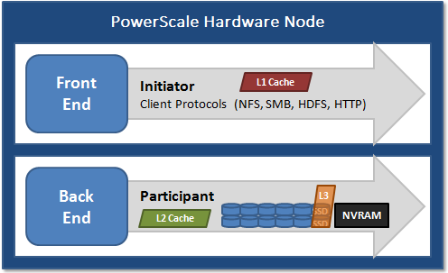
L2, or back-end cache, refers to local memory on the node on which a particular block of data is stored. L2 reduces the latency of a read operation by not requiring a seek directly from the disk drives. As such, the amount of data prefetched into L2 cache for use by remote nodes is much greater than that in L1 cache.
L2 is also known as local cache because it contains data retrieved from disk drives located on that node and then made available for requests from remote nodes. Data in L2 cache is evicted according to a Least Recently Used (LRU) algorithm. Data in L2 cache is addressed by the local node using an offset into a disk drive which is local to that node. Because the node knows where the data requested by the remote nodes is located on disk, this is a very fast way of retrieving data destined for remote nodes. A remote node accesses L2 cache by doing a lookup of the block address for a particular file object. As described above, there is no MESI invalidation necessary here and the cache is updated automatically during writes and kept coherent by the transaction system and NVRAM.
L3 cache is a subsystem that caches evicted L2 blocks on a node. Unlike L1 and L2, not all nodes or clusters have an L3 cache, because it requires solid state drives (SSDs) to be present and exclusively reserved and configured for caching use. L3 serves as a large, cost-effective way of extending a node’s read cache from gigabytes to terabytes. This allows clients to retain a larger working set of data in cache, before being forced to retrieve data from higher latency spinning disk. The L3 cache is populated with “interesting” L2 blocks dropped from memory by L2’s least recently used cache eviction algorithm. Unlike RAM based caches, because L3 is based on persistent flash storage, once the cache is populated, or warmed, it’s highly durable and persists across node reboots, and so on. L3 uses a custom log-based file system with an index of cached blocks. The SSDs provide very good random read access characteristics, such that a hit in L3 cache is not that much slower than a hit in L2.
To use multiple SSDs for cache effectively and automatically, L3 uses a consistent hashing approach to associate an L2 block address with one L3 SSD. In the event of an L3 drive failure, a portion of the cache will obviously disappear, but the remaining cache entries on other drives will still be valid. Before a new L3 drive can be added to the hash, some cache entries must be invalidated.
OneFS also uses a dedicated inode cache in which recently requested inodes are kept. The inode cache frequently has a large impact on performance, because clients often cache data, and many network I/O activities are primarily requests for file attributes and metadata, which can be quickly returned from the cached inode.
OneFS provides tools to accurately assess the performance of the various levels of cache at a point in time. These cache statistics can be viewed from the OneFS CLI using the isi_cache_stats command. Statistics for L1, L2, and L3 cache are displayed for both data and metadata. For example:
# isi_cache_stats Totals l1_data: a 224G 100% r 226G 100% p 318M 77%, l1_encoded: a 0.0B 0% r 0.0B 0% p 0.0B 0%, l1_meta: r 4.5T 99% p 152K 48%, l2_data: r 1.2G 95% p 115M 79%, l2_meta: r 27G 72% p 28M 3%, l3_data: r 0.0B 0% p 0.0B 0%, l3_meta: r 8G 99% p 0.0B 0%
For more detailed and formatted output, a verbose option of the command is available using the ‘isi_cache_stats -v’ option.
It’s worth noting that for L3 cache, the prefetch statistics will always read zero, since it’s a pure eviction cache and does not use data or metadata prefetch.
Due to balanced data distribution, automatic rebalancing, and distributed processing, OneFS is able to leverage additional CPUs, network ports, and memory as the system grows. This also allows the caching subsystem (and, by virtue, throughput and IOPS) to scale linearly with the cluster size.
Author: Nick Trimbee
Related Blog Posts
OneFS and HTTP Security
Mon, 22 Apr 2024 20:35:30 -0000
|Read Time: 0 minutes
To enable granular HTTP security configuration, OneFS provides an option to disable nonessential HTTP components selectively. This can help reduce the overall attack surface of your infrastructure. Disabling a specific component’s service still allows other essential services on the cluster to continue to run unimpeded. In OneFS 9.4 and later, you can disable the following nonessential HTTP services:
Service | Description |
PowerScaleUI | The OneFS WebUI configuration interface. |
Platform-API-External | External access to the OneFS platform API endpoints. |
Rest Access to Namespace (RAN) | REST-ful access by HTTP to a cluster’s /ifs namespace. |
RemoteService | Remote Support and In-Product Activation. |
SWIFT (deprecated) | Deprecated object access to the cluster using the SWIFT protocol. This has been replaced by the S3 protocol in OneFS. |
You can enable or disable each of these services independently, using the CLI or platform API, if you have a user account with the ISI_PRIV_HTTP RBAC privilege.
You can use the isi http services CLI command set to view and modify the nonessential HTTP services:
# isi http services list ID Enabled ------------------------------ Platform-API-External Yes PowerScaleUI Yes RAN Yes RemoteService Yes SWIFT No ------------------------------ Total: 5
For example, you can easily disable remote HTTP access to the OneFS /ifs namespace as follows:
# isi http services modify RAN --enabled=0
You are about to modify the service RAN. Are you sure? (yes/[no]): yes
Similarly, you can also use the WebUI to view and edit a subset of the HTTP configuration settings, by navigating to Protocols > HTTP settings:
That said, the implications and impact of disabling each of the services is as follows:
Service | Disabling impacts |
WebUI | The WebUI is completely disabled, and access attempts (default TCP port 8080) are denied with the warning Service Unavailable. Please contact Administrator. If the WebUI is re-enabled, the external platform API service (Platform-API-External) is also started if it is not running. Note that disabling the WebUI does not affect the PlatformAPI service. |
Platform API | External API requests to the cluster are denied, and the WebUI is disabled, because it uses the Platform-API-External service. Note that the Platform-API-Internal service is not impacted if/when the Platform-API-External is disabled, and internal pAPI services continue to function as expected. If the Platform-API-External service is re-enabled, the WebUI will remain inactive until the PowerScaleUI service is also enabled. |
RAN | If RAN is disabled, the WebUI components for File System Explorer and File Browser are also automatically disabled. From the WebUI, attempts to access the OneFS file system explorer (File System > File System Explorer) fail with the warning message Browse is disabled as RAN service is not running. Contact your administrator to enable the service. This same warning also appears when attempting to access any other WebUI components that require directory selection. |
RemoteService | If RemoteService is disabled, the WebUI components for Remote Support and In-Product Activation are disabled. In the WebUI, going to Cluster Management > General Settings and selecting the Remote Support tab displays the message The service required for the feature is disabled. Contact your administrator to enable the service. In the WebUI, going to Cluster Management > Licensing and scrolling to the License Activation section displays the message The service required for the feature is disabled. Contact your administrator to enable the service. |
SWIFT | Deprecated object protocol and disabled by default. |
You can use the CLI command isi http settings view to display the OneFS HTTP configuration:
# isi http settings view Access Control: No Basic Authentication: No WebHDFS Ran HTTPS Port: 8443 Dav: No Enable Access Log: Yes HTTPS: No Integrated Authentication: No Server Root: /ifs Service: disabled Service Timeout: 8m20s Inactive Timeout: 15m Session Max Age: 4H Httpd Controlpath Redirect: No
Similarly, you can manage and change the HTTP configuration using the isi http settings modify CLI command.
For example, to reduce the maximum session age from four to two hours:
# isi http settings view | grep -i age Session Max Age: 4H # isi http settings modify --session-max-age=2H # isi http settings view | grep -i age Session Max Age: 2H
The full set of configuration options for isi http settings includes:
Option | Description |
--access-control <boolean> | Enable Access Control Authentication for the HTTP service. Access Control Authentication requires at least one type of authentication to be enabled. |
--basic-authentication <boolean> | Enable Basic Authentication for the HTTP service. |
--webhdfs-ran-https-port <integer> | Configure Data Services Port for the HTTP service. |
--revert-webhdfs-ran-https-port | Set value to system default for --webhdfs-ran-https-port. |
--dav <boolean> | Comply with Class 1 and 2 of the DAV specification (RFC 2518) for the HTTP service. All DAV clients must go through a single node. DAV compliance is NOT met if you go through SmartConnect, or using 2 or more node IPs. |
--enable-access-log <boolean> | Enable writing to a log when the HTTP server is accessed for the HTTP service. |
--https <boolean> | Enable the HTTPS transport protocol for the HTTP service. |
--integrated-authentication <boolean> | Enable Integrated Authentication for the HTTP service. |
--server-root <path> | Document root directory for the HTTP service. Must be within /ifs. |
--service (enabled | disabled | redirect | disabled_basicfile) | Enable/disable the HTTP Service or redirect to WebUI or disabled BasicFileAccess. |
--service-timeout <duration> | The amount of time (in seconds) that the server will wait for certain events before failing a request. A value of 0 indicates that the service timeout value is the Apache default. |
--revert-service-timeout | Set value to system default for --service-timeout. |
--inactive-timeout <duration> | Get the HTTP RequestReadTimeout directive from both the WebUI and the HTTP service. |
--revert-inactive-timeout | Set value to system default for --inactive-timeout. |
--session-max-age <duration> | Get the HTTP SessionMaxAge directive from both WebUI and HTTP service. |
--revert-session-max-age | Set value to system default for --session-max-age. |
--httpd-controlpath-redirect <boolean> | Enable or disable WebUI redirection to the HTTP service. |
Note that while the OneFS S3 service uses HTTP, it is considered a tier-1 protocol, and as such is managed using its own isi s3 CLI command set and corresponding WebUI area. For example, the following CLI command forces the cluster to only accept encrypted HTTPS/SSL traffic on TCP port 9999 (rather than the default TCP port 9021):
# isi s3 settings global modify --https-only 1 –https-port 9921 # isi s3 settings global view HTTP Port: 9020 HTTPS Port: 9999 HTTPS only: Yes S3 Service Enabled: Yes
Additionally, you can entirely disable the S3 service with the following CLI command:
# isi services s3 disable The service 's3' has been disabled.
Or from the WebUI, under Protocols > S3 > Global settings:
Author: Nick Trimbee
OneFS and PowerScale F-series Management Ports
Mon, 22 Apr 2024 20:12:20 -0000
|Read Time: 0 minutes
Another security enhancement that OneFS 9.5 and later releases brings to the table is the ability to configure 1GbE NIC ports dedicated to cluster management on the PowerScale F900, F710, F600, F210, and F200 all-flash storage nodes and P100 and B100 accelerators. Since these platforms were released, customers have been requesting the ability to activate the 1GbE NIC ports so that the node management activity and front end protocol traffic can be separated on physically distinct interfaces.
For background, since their introduction, the F600 and F900 have shipped with a quad port 1GbE rNDC (rack Converged Network Daughter Card) adapter. However, these 1GbE ports were non-functional and unsupported in OneFS releases prior to 9.5. As such, the node management and front-end traffic was co-mingled on the front-end interface.
In OneFS 9.5 and later, 1GbE network ports are now supported on all of the PowerScale PowerEdge based platforms for the purposes of node management, and are physically separate from the other network interfaces. Specifically, this enhancement applies to the F900, F600, F200 all-flash nodes, and P100 and B100 accelerators.
Under the hood, OneFS has been updated to recognize the 1GbE rNDC NIC ports as usable for a management interface. Note that the focus of this enhancement is on factory enablement and support for existing F600 customers that have the unused 1GbE rNDC hardware. This functionality has also been back-ported to OneFS 9.4.0.3 and later RUPs. Since the introduction of this feature, there have been several requests raised about field upgrades, but that use case is separate and will be addressed in a later release through scripts, updates of node receipts, procedures, and so on.
Architecturally, aside from some device driver and accounting work, no substantial changes were required to the underlying OneFS or platform architecture to implement this feature. This means that in addition to activating the rNDC, OneFS now supports the relocated front-end NIC in PCI slots 2 or 3 for the F200, B100, and P100.
OneFS 9.5 and later recognizes the 1GbE rNDC as usable for the management interface in the OneFS Wizard, in the same way it always has for the H-series and A-series chassis-based nodes.
All four ports in the 1GbE NIC are active, and for the Broadcom board, the interfaces are initialized and reported as bge0, bge1, bge2, and bge3.
The pciconf CLI utility can be used to determine whether the rNDC NIC is present in a node. If it is, a variety of identification and configuration details are displayed. For example, let’s look at the following output from a Broadcom rNDC NIC in an F200 node:
# pciconf -lvV pci0:24:0:0
bge2@pci0:24:0:0: class=0x020000 card=0x1f5b1028 chip=0x165f14e4 rev=0x00 hdr=0x00 class = network subclass = ethernet VPD ident = ‘Broadcom NetXtreme Gigabit Ethernet’ VPD ro PN = ‘BCM95720’ VPD ro MN = ‘1028’ VPD ro V0 = ‘FFV7.2.14’ VPD ro V1 = ‘DSV1028VPDR.VER1.0’ VPD ro V2 = ‘NPY2’ VPD ro V3 = ‘PMT1’ VPD ro V4 = ‘NMVBroadcom Corp’ VPD ro V5 = ‘DTINIC’ VPD ro V6 = ‘DCM1001008d452101000d45’
We can use the ifconfig CLI utility to determine the specific IP/interface mapping on the Broadcom rNDC interface. For example:
# ifconfig bge0 TME-1: bge0: flags=8843<UP,BROADCAST,RUNNING,SIMPLEX,MULTICAST> metric 0 mtu 1500 TME-1: ether 00:60:16:9e:X:X TME-1: inet 10.11.12.13 netmask 0xffffff00 broadcast 10.11.12.255 zone 1 TME-1: inet 10.11.12.13 netmask 0xffffff00 broadcast 10.11.12.255 zone 0 TME-1: media: Ethernet autoselect (1000baseT <full-duplex>) TME-1: status: active
In this output, the first IP address of the management interface’s pool is bound to bge0, which is the first port on the Broadcom rNDC NIC.
We can use the isi network pools CLI command to determine the corresponding interface. Within the system zone, the management interface is allocated an address from the configured IP range within its associated interface pool. For example:
# isi network pools list ID SC Zone IP Ranges Allocation Method ---------------------------------------------------------------------------------------------- groupnet0.mgt.mgt cluster_mgt_isln.com 10.11.12.13-10.11.12.20 static # isi network pools view groupnet0.mgt.mgt | grep -i ifaces Ifaces: 1:mgmt-1, 2:mgmt-1, 3:mgmt-1, 4:mgmt-1, 5:mgmt-1
Or from the WebUI, under Network configuration > External network:
Drilling down into the mgt pool details shows the 1GbE management interfaces as the pool interface members:
Note that the 1GbE rNDC network ports are solely intended as cluster management interfaces. As such, they are not supported for use with regular front-end data traffic.
The F900 and F600 nodes already ship with a four port 1GbE rNDC NIC installed. However, the F200, B100, and P100 platform configurations have also been updated to include a quad port 1GbE rNDC card. These new configurations have been shipping by default since January 2023. This required relocating the front end network’s 25GbE NIC (Mellanox CX4) to PCI slot 2 in the motherboard. Additionally, the OneFS updates needed for this feature have also now allowed the F200 platform to be offered with a 100GbE option too. The 100GbE option uses a Mellanox CX6 NIC in place of the CX4 in slot 2.
With this 1GbE management interface enhancement, the same quad-port rNDC card (typically the Broadcom 5720) that has been shipped in the F900 and F600 since their introduction, is now included in the F200, B100 and P100 nodes as well. All four 1GbE rNDC ports are enabled and active under OneFS 9.5 and later, too.
Node port ordering continues to follow the standard, increasing numerically from left to right. However, be aware that the port labels are not visible externally because they are obscured by the enclosure’s sheet metal.
The following back-of-chassis hardware images show the new placements of the NICs in the various F-series and accelerator platforms:
F600
F900
For both the F600 and F900, the NIC placement remains unchanged, because these nodes have always shipped with the 1GbE quad port in the rNDC slot since their launch.
F200
The F200 sees its front-end NIC moved to slot 3, freeing up the rNDC slot for the quad-port 1GbE Broadcom 5720.
Because the B100 backup accelerator has a fibre-channel card in slot 2, it sees its front-end NIC moved to slot 3, freeing up the rNDC slot for the quad-port 1GbE Broadcom 5720.
Finally, the P100 accelerator sees its front-end NIC moved to slot 3, freeing up the rNDC slot for the quad-port 1GbE Broadcom 5720.
Note that, while there is currently no field hardware upgrade process for adding rNDC cards to legacy F200 nodes or B100 and P100 accelerators, this will be addressed in a future release.
Author: Nick Trimbee