
Hardware redundancy
Hardware redundancy
-
PowerStore has a dual-node architecture which includes two identical nodes for redundancy. It features an active/active controller configuration in which both nodes service I/O simultaneously. This feature increases hardware efficiency since there are no requirements for idle-standby hardware. The base enclosure includes these nodes and up to twenty-five 2.5-inch drives. On all models except PowerStore 500, twenty-one slots are available for data drives and four slots are reserved for the NVRAM drives. The NVRAM drives operate as mirrored pairs to provide redundancy. PowerStore 500 does not have NVRAM drives so all twenty-five slots are available for data drives.
For details about the components of PowerStore 1000 to 9000, PowerStore 1200 to 9200 (available since PowerStoreOS 3.0), PowerStore 3200Q (available since PowerStoreOS 4.0), and PowerStore 500 appliances, see these documents:
- PowerStore Hardware Information Guide on dell.com/powerstoredocs
- PowerStore Hardware Information Guide for 500T on dell.com/powerstoredocs
See also the white paper PowerStore: Introduction to the Platform on the PowerStore Info Hub.
Management software
The management software runs PowerStore Manager, the management interface (cluster IP), and other services such as REST API. For PowerStore systems running on versions earlier than PowerStoreOS 3.0, all the management software runs on one node in the appliance at a time. In these previous versions of PowerStoreOS, the node that runs the management software is designated as the primary node in PowerStore Manager. Figure 22 shows an example of a primary node from the hardware properties page, which is highlighted by going to Hardware > Appliance > Components > Rear View.
In PowerStoreOS 3.0 and later, the management resources have been balanced and split between both nodes of the appliance to promote better CPU utilization on each of the appliance nodes. In PowerStoreOS 3.0 and later, PowerStore Manager runs on the secondary node while the other management services run on the primary node.
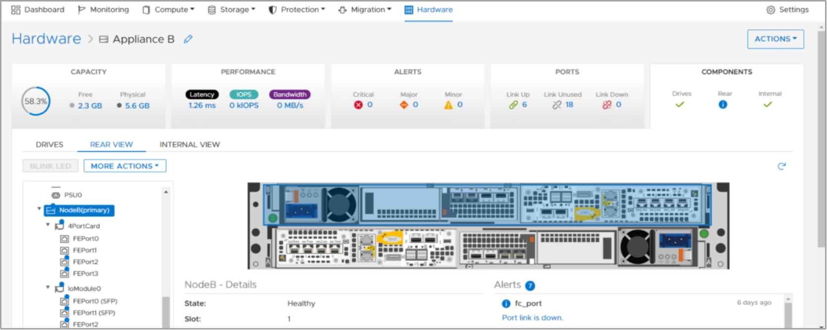
Figure 22. Primary node
If a node reboots, crashes, or the management connection goes down, the services running on that node automatically fail over to the peer node. After a failover, it might take several minutes for all services to start completely. Users that are logged in to PowerStore Manager during the failover might see a message indicating that the connection has been lost. When the failover process completes, access to PowerStore Manager is automatically restored, however users can also manually refresh the browser to regain access. Host access to storage resources is prioritized and available before PowerStore Manager is accessible.
After the failover, the services temporarily run on the new node. When the peer node has recovered from the failover event, the services automatically rebalance after five minutes. During the rebalance, PowerStore Manager might lose connection for up to three minutes while services are brought back up on the recovered node. Note that after failover events, the primary node might change to the peer node and will remain this way until the system is rebooted or failed over again.
System bond
PowerStore systems ensure that there is no single point of failure throughout the system. For a PowerStore T/Q model appliance, we recommend cabling the first two ports of the 4-port card to a top-of-rack switch as shown in the following figure. For the PowerStore T/Q model, these ports are internally referred to as the system bond. This interface is created to ensure that there is no single point of failure and data services and production data are always available. The list below shows the different types of traffic that flow through the system bond if the data services are leveraged on the PowerStore system:
- Cluster communication
- iSCSI or NVMe/TCP host traffic (optional)
- Replication traffic (optional)
- NAS traffic (for PowerStore T/Q models) (optional)
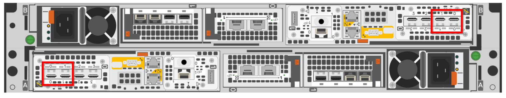
Figure 23. First two ports of the 4-port card (system bond)
For PowerStore T/Q model appliances, the individual ports within the system bond could be running in active/active mode or active/passive mode. This state depends on whether Link Aggregation Control Protocol (LACP) is configured on the network switches. To ensure best resiliency and network performance, we recommend enabling LACP on the network. To learn more about LACP with PowerStore, see the section Link Aggregation Control Protocol (LACP) in this document. For more information about configuring LACP for a PowerStore T/Q model appliance, see the document PowerStore Guide for PowerStore T Models on the dell.com/powerstoredocs.
PowerStore enables adding more ports for extra bandwidth or increasing fault tolerance. Administrators can extend storage traffic by mapping the extra physical ports, or virtual ports (if applicable) associated with the appliances in the cluster. For a PowerStore T/Q model appliance, administrators can also untag and remove replication traffic from the system bond ports if replication traffic is already tagged to other ports on the 4-port card or I/O modules. For more information about how to add additional ports for host connectivity, see the section Ethernet configuration. For information about how to enable and scale replication traffic, see the white paper PowerStore: Replication Technologies.
User Defined Link Aggregation (bond)
PowerStoreOS 4.0 and later allows users to map iSCSI and Replication networks to user defined link aggregated ports (bonds) utilizing LACP. Previously iSCSI and replication networks were limited to the system bond (bond0) or any individual ethernet port capable of supporting a storage network. The link aggregated ports can then be utilized for host or replication purposes. Like with the system bond, selecting ports on different IO modules is suggested. The figure below shows a User Defined Link Aggregation (bond) has been created as bond1. The system will automatically name the bond starting with 1 and increase the number in order as more bonds are created. Once the bond has been created the user can easily map a storage network by selecting the bond and clicking the MAP STORAGE NETWORK button.
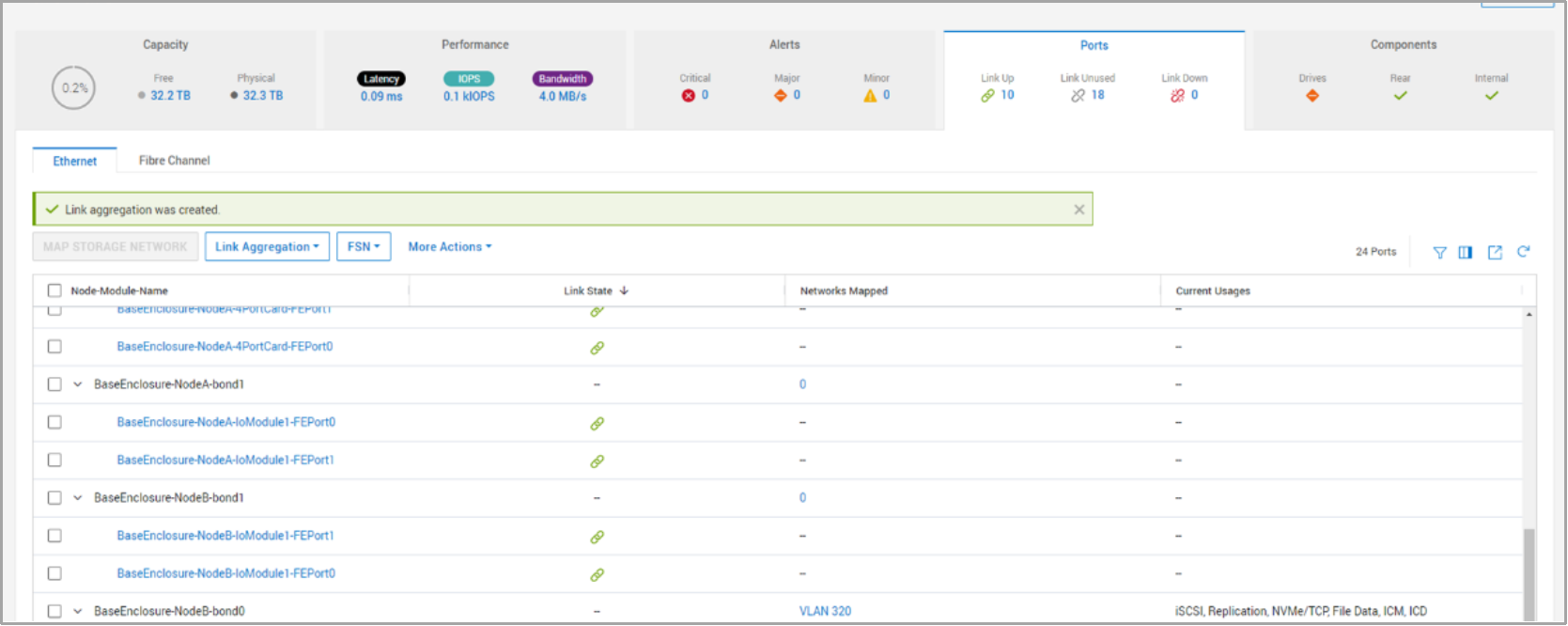
Figure 24. User Defined Link Aggregation
Note: User Defined Link aggregation does not support the NVMe/TCP protocol. It may be utilized on the system created bond or bond0.