
Assets

Serverless Workload and APEX Private Cloud
Mon, 29 Apr 2024 13:18:52 -0000
|Read Time: 0 minutes
What is a serverless service?
To begin answering this question, let’s build upon my previous blog in which I walked through how a developer can deploy a machine-learning workload on APEX Private Cloud Services. Now, I’ll expand on this workload example and demonstrate how to deploy it as a serverless service.
A serverless service is constructed in a serverless architecture, a development model that allows developers to build and run applications without managing the infrastructure. Combining serverless architecture and APEX Cloud Services can provide developers with a robust environment for their application development.
Knative Serving and Eventing
Knative is a popular open-source Kubernetes-based platform to deploy and manage modern serverless workloads. It consists of two main components: Serving and Eventing.
Knative Serving builds on Kubernetes and a network layer to support deploying and serving serverless applications/functions. Serving is easy to get started with, and it scales to support complex scenarios.
The Knative Serving project provides middleware components that enable:
- Rapid deployment of serverless containers
- Autoscaling, including scaling pods down to zero
- Support for multiple networking layers such as Ambassador, Contour, Kourier, Gloo, and Istio for integration into existing environments
- Point-in-time snapshots of deployed code and configurations
Knative Eventing enables developers to use an event-driven architecture with serverless applications. An event-driven architecture is based on the concept of decoupled relationships between event producers that create events and event consumers, or sinks, that receive events.
Examples of event sources for applications include Slack, Zendesk, and VMware.
Deployment demo
Following the Knative installation instructions, I configured Knative in my cluster. Next, I configured real DNS in my environment.
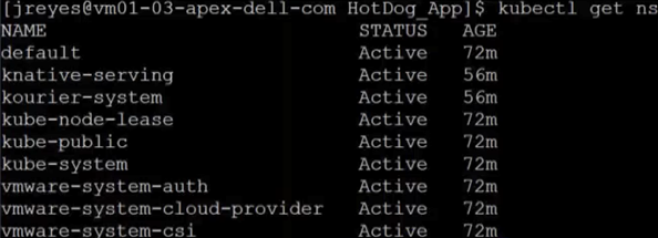
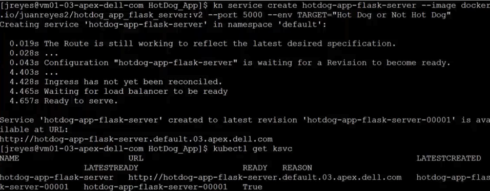
I also installed the Knative CLI through homebrew to make deploying of Knative services easier. Using the kn CLI, I wrapped my flask server in the serving framework. After a successful deployment, I used the following command to view the current Knative services:
kubectl get ksvc
You can see from the screenshots how the pods get created and destroyed as the service receives traffic.
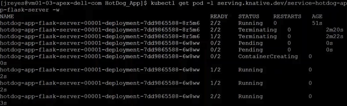
Now, the serverless user interphase can request predictions from my model.
Kserve
My first attempt to wrap the TensorFlow service with Knative wasn't effective. The service dropped the opening requests, and the response times were slower. The spinning up and down of the pods was creating the delay and the execution drops. I fixed these issues by having a constant heartbeat so that the pods would stay active. Unfortunately, this workaround defeats some of the benefits of Knative. This was not the way for me to move forward.
In my quest to have the model in a serverless framework, I came across Kubeflow.
Kubeflow is a free and open-source machine-learning platform designed to use machine-learning pipelines to orchestrate complicated workflows running on Kubernetes.
Kubeflow integrates with Knative to deploy and train ML models. Kserve is the part of Kubeflow used for serving machine-learning models on arbitrary frameworks. Kserve recently graduated from the Kubeflow project, and you can configure it by itself without installing the whole suite of Kubeflow.
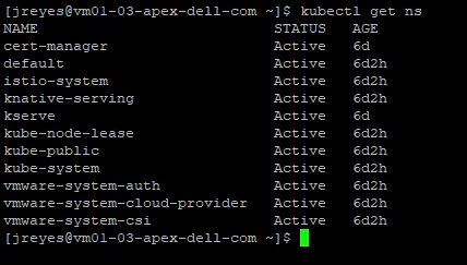
Following the Kserve installation guide, I configured it in my cluster.
Creating the YAML file for this service is straightforward enough. However, the tricky part was entering the correct storageUri for my APEX Private Cloud environment. This parameter is the path to the model’s location, and depending on the storage used, it can look a little different. For example, for APC, we need to save the model in a persistent volume claim (pvc).
Here is the YAML file code snippet I used to create the pvc:
apiVersion: v1
kind: PersistentVolumeClaim
metadata:
  name: task-pv-claim-1
spec:
  storageClassName: vsan-default-storage-policy
  accessModes:
    - ReadWriteOnce
  resources:
    requests:
      storage: 1Gi
Once the pvc is formed, we need to copy the model to the pv. I achieved this by creating a pod and attaching the volume. After the pod is created, we can copy the model to the pvc directory.
#pv-model-store.yaml
apiVersion: v1
kind: Pod
metadata:
  name: model-store-pod
spec:
  volumes:
    - name: model-store
      persistentVolumeClaim:
        claimName: task-pv-claim-1
  containers:
    - name: model-store
      image: ubuntu
      command: [ "sleep" ]
      args: [ "infinity" ]
      volumeMounts:
        - mountPath: "/pv"
          name: model-store
      resources:
        limits:
          memory: "1Gi"
          cpu: "1"
  imagePullSecrets:
    - name: regcred
By running the following command, we can copy the model to the PVC:
kubectl cp [model folder location] [name of pod with PVC]:[new location within PVC] -c model-store
kubectl cp /home/jreyes/HotDog_App/hotdog_image_classification_model/new_model model-store-pod:/pv/hotdog/1 -c model-store
The critical part is not forgetting to add a version number to the model. In this case, I added version number 1 to the end of the path.
Once the model is stored, we can log in to the pod to verify the contents using the following command:
kubectl exec -it model-store-pod – bash
After verification, we need to delete the pod to free up the pvc.
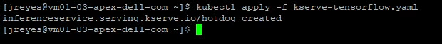
We can now run the Kserve Inference service YAML file that will use the pvc.
apiVersion: "serving.kserve.io/v1beta1"
kind: "InferenceService"
metadata:
  name: "hotdog"
spec:
  predictor:
    tensorflow:
      storageUri: "pvc://task-pv-claim-1/hotdog"
The TensorFlow serving container automatically looks for the version inside the folder, so there is no need to add the version number in the storageUri path.
After executing the YAML file, we can find the address of our Kserve service with the following command:
kubectl get isvc
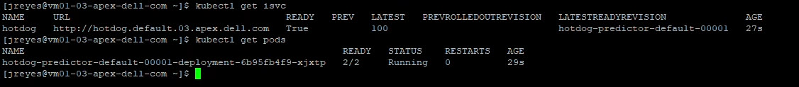
With this address, we can update the resnet client to test the model.
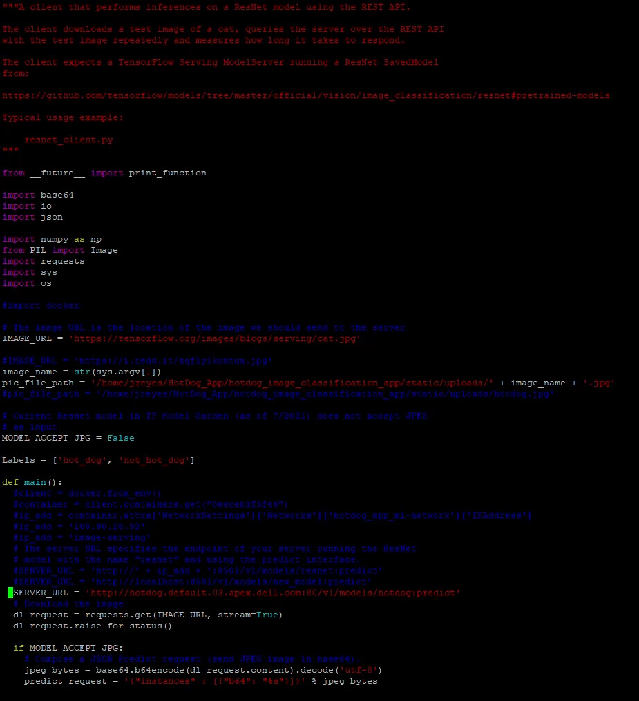
Here are the predictions when we run the client with two different images:
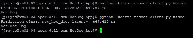
We have successfully made our user interface and model use a serverless framework. The final step is to update the flask server to point to the new address.
Note: I could not get an inference service to listen to two ports at a time (REST and gRPC). My solution was to create two inference services and adjust the flask code as necessary.
Conclusion
Now, we have a complete image-recognition application on a serverless architecture. The serverless architecture grants us greater resource flexibility with autoscaling and facilitates a canary deployment for the machine-learning model. Furthermore, combining this architecture with APEX Private Cloud services provides an environment that is powerful and flexible for many edge application deployments. In my next blog, I will cover migrating the application to the public cloud to compare the differences and provide a cost analysis.
Until next time!
Author: Juan Carlos Reyes

Deploying ML Application on APEX Private
Mon, 29 Apr 2024 13:15:27 -0000
|Read Time: 0 minutes
The purpose of this blog is to show users how to develop applications in the APEX Private Cloud services with VMware Tanzu environment. I will demonstrate this by walking through the steps required to deploy an image recognition application. This initial, hefty, post contains important details that will be helpful for understanding key concepts about the deployment process, so take your time and follow along.
For the machine learning portion of this project, I am using TensorFlow. I researched the framework and I am learning as I go. I’ll share my experiences and explain all the different components that come with this project.
We can break down the process into six sections:
- The environment: APEX Cloud services with VMware Tanzu
- Deploying and testing a custom model with TensorFlow.
- Creating a basic user interface with Python and Flask
- Using Docker to deploy the application locally
- Deploying the application to the APEX Private/Hybrid with VMware Tanzu
- Note: Similar steps can be taken to deploy the application in an APEX Hybrid environment
- Consistent hybrid cloud offering public and private deployment options
The environment: APEX Cloud services with VMware Tanzu
APEX Cloud services offers two options, Private and Hybrid. APEX Private Cloud is based on VMware vSphere Enterprise Plus and VMware vSAN. APEX Hybrid Cloud is built on VMware Cloud Foundation, which allows full automation and workload orchestration spanning a customer’s complete cloud environment.
Here are the details of the appliances and software used in the environment for this walkthrough.
I am using an APEX Private Cloud instance, which is composed of four VxRail nodes (E560F) running version 7.0.203. I have also enabled Tanzu workloads on my instance. For my Tanzu Kubernetes Grid (TKG) cluster (v1.19.7+vmware.1-tkg.1.fc82c41), I am running one control plane node and three worker nodes, running the best-effort-large t-shirt size (4 cores x 16 GB of RAM) and 100 GB of vSAN storage. I am also using a CentOS 8 virtual machine deploy in my APEX Private Cloud instance. The specs of this VM are the same as my TKG nodes, but with 500GB of vSAN storage to hold the training images. This VM will serve as my developer VM to train my custom model and login to my TKG cluster.
Deploying and testing a custom model with TensorFlow.
First, I need to configure my developer machine. To do this, I have to install the latest versions of Docker, Python, TensorFlow, TKG CLI, Kubernetes CLI, and Kompose. I will also use Docker Hub to store the containers, which requires me to log in to my account.
I'll use the official TensorFlow serving container, but there are many other variations available, such as the Bitnami TensorFlow container.
I recommend using the Bitnami container after you are ready to deploy an application to production because it has several security features such as non-root containers.
Note: The details on how to create a custom TensorFlow model are located in the Bitbucket repository.
First, I pull the image from Docker:
$ docker pull tensorflow/serving
Now that the image is on our local machine, I can run the container with our model using the following command:
$ docker run -p 8500:8500 -p 8501:8501 \
   --mount type=bind,source=/path/to/[my_model_name]/,target=/models/[my_model_name]/1 \
--name [container_name] -it tensorflow/serving
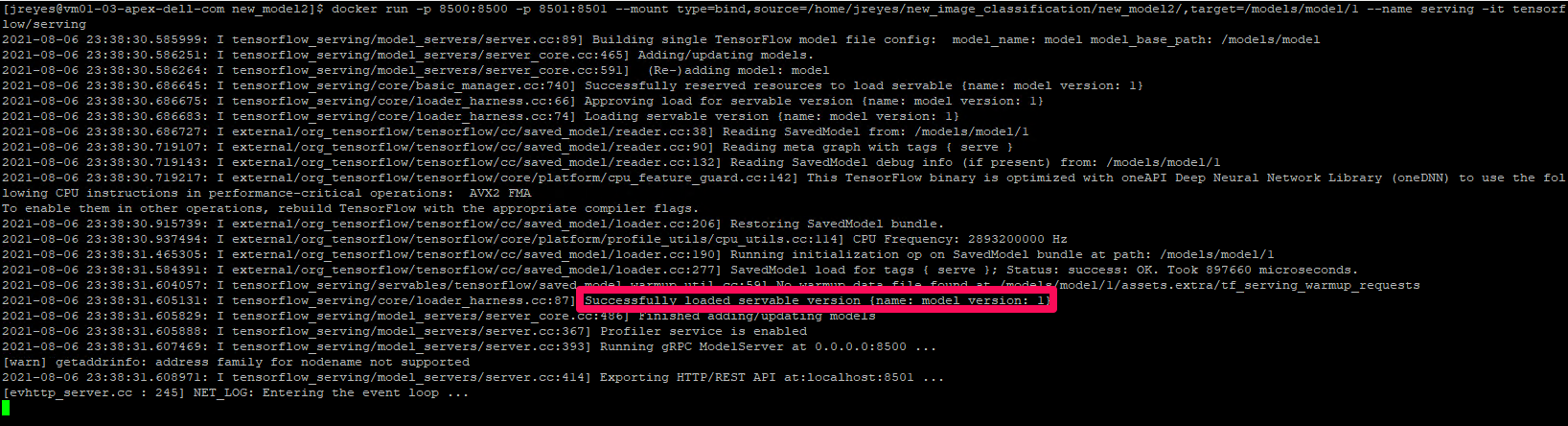
Note: In the mount target, the number 1 after the model name represents the version of your model. You can have various model versions and then specify which version you want the container to run.
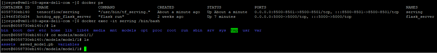
Sanity check: If the container can’t find a model, it will keep logging a message indicating the model was not found. If it finds the protobuf file in the expected location, it will display the message highlighted in the previous above. You can also open a new terminal, log into the docker container, and navigate to the models:
/[my_model_name]/1 folder to view the protobuf file:
$ docker exec -it [container_name] /bin/bash
$ ls models/[my_model_name]/1
If for some reason your model didn’t copy during start up, you can manually copy your files to the container:
$ docker cp /path/to/[my_model_name]/ [container_name]:/models/[my_model_name ]/1/
The gRPC port (8500) and the REST API port (8501) were exposed when the container was initialized. In the following steps, I test both protocols to see if they are responding appropriately.
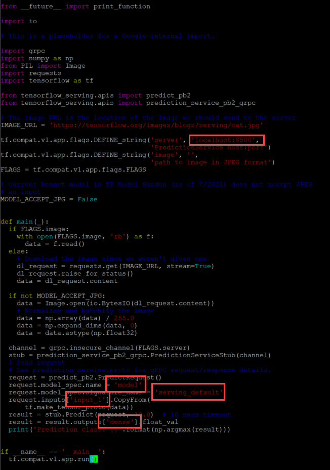
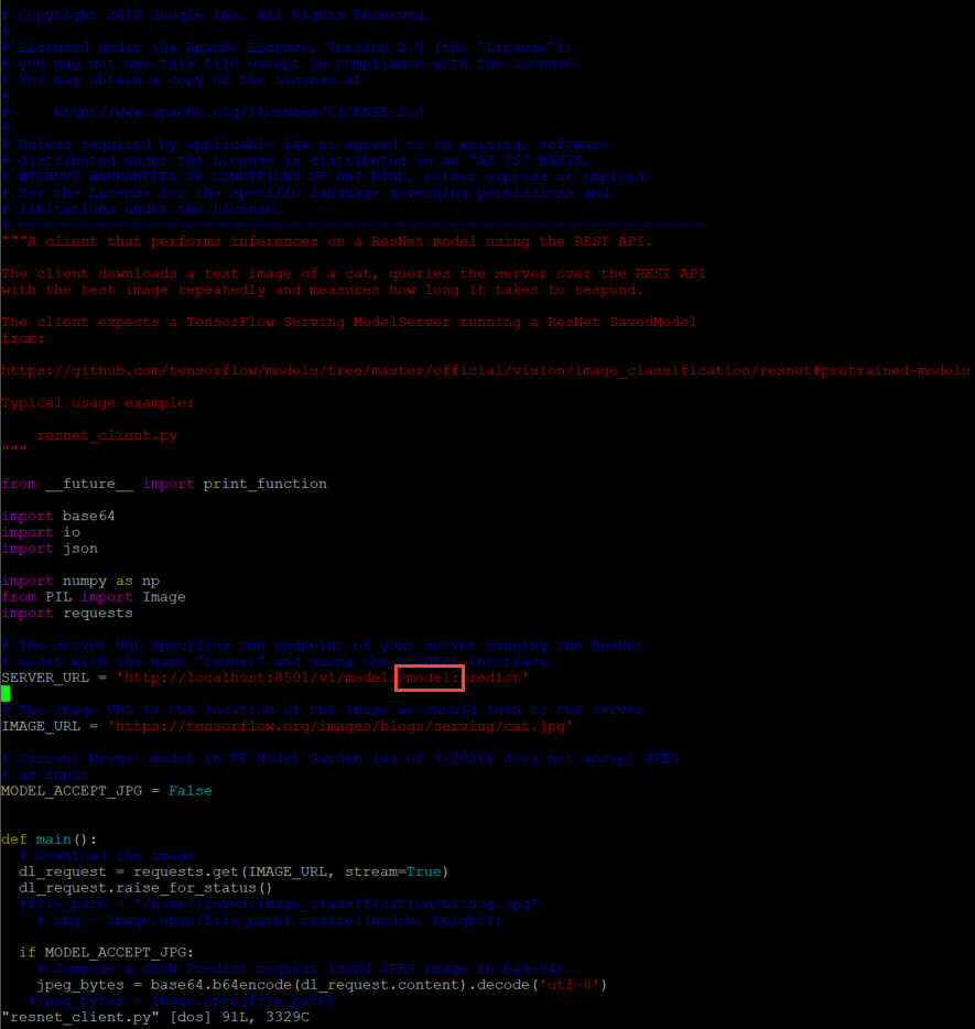
The TensorFlow git has template scripts to call a protobuf model via the gRPC protocol (resnet_client_grpc.py) and the REST API (resnet_client.py), and they need a few modifications.
The gRPC script needs the model signature, input, and output variable names of the model. To get this information, run the saved_model CLI:
$ saved_model_cli show --dir
/home/jreyes/HotDog_App/hotdog_image_classification_model/new_model –all
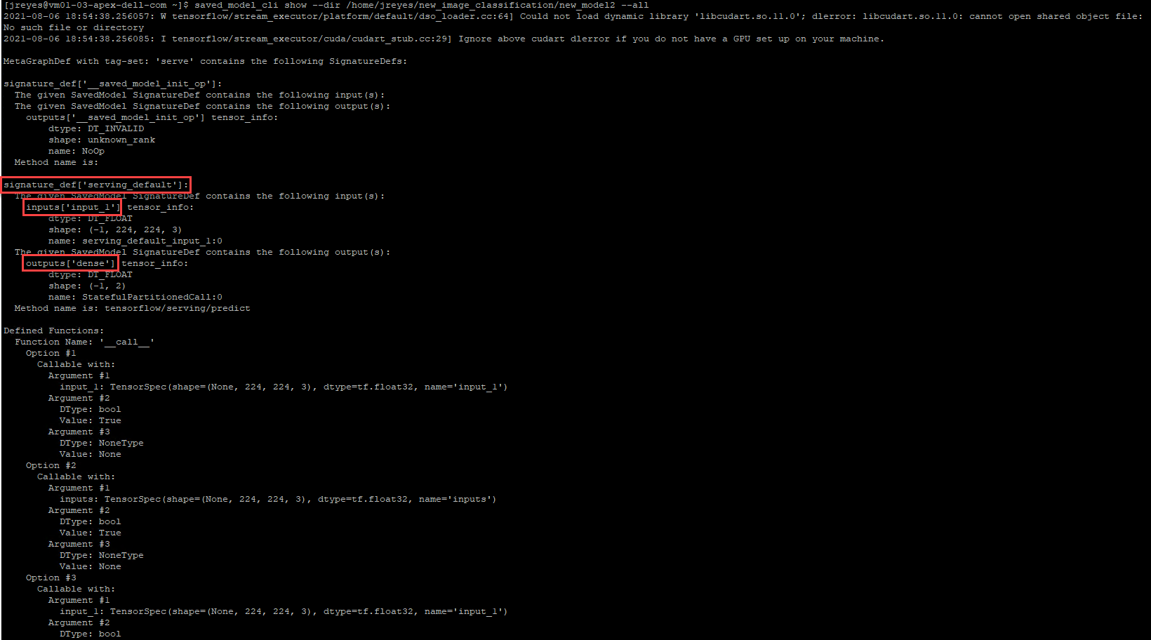
After the output is displayed, I can record the necessary values to modify the gRPC script accordingly.
For the REST API script, I have to modify the URL to call the correct model.
Now let's test these scripts.
$ python3 resnet_client_grpc.py

$ python3 resnet_client.py

Success! The results show the value 1, which points to the not_hot_dog value in the labels array. The default image is a cat.png, so the label is appropriate. You can modify the image processed to a hot dog image to verify that the script labels it correctly.
Note: In my repository, you will see that I made some modifications to the scripts to call different images inline (time saver while debugging so I wouldn't have to modify the script every time). I added a time variable to the gRPC script to check how long it takes the server to respond with a prediction.
The next step is to save the custom model container and push it to Docker Hub.
Note: It is also possible to save the image to a private container registry such as Harbor Registry. If you want to create a local instance of Harbor Registry, you can deploy it from the Bitnami apps to your Kubernetes cluster. Or if you are running APEX Hybrid Cloud you can enable the embedded Harbor Registry on the Supervisor Cluster.
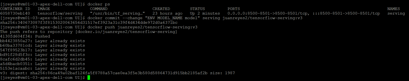
Use the following commands to commit the TensorFlow serving container:
 $ docker commit --change "ENV MODEL_NAME [my_model_name ]" [container_name] [docker_username]/ [image_name]:[tag]
$ docker push [docker_username]/ [image_name]:[tag]
Creating a basic user interface with Python and Flask
Now that I have verified that the model works, I can create the user interface.
To begin, I created a new folder that contains all of my UI files to separate them from my model files. I'll be using a simple flask web server interface. Users will be able to upload a file and submit the request to the TensorFlow server. The output will be the uploaded image, the label predicted by the model, and the time it took for the model to make the prediction.
Here is the link to the repository for further inspection.
The structure of the HTML portion looks like this:
Main UI folder
|------ Templates
        |------ Layout.html
|------ Index.html
        |------ Upload.html
|------ Static
        |------ CSS
                 |------ Main.css
        |------ Uploads - location where images will be saved
                 |------ Test images
Here’s a breakdown of the HTML structure:
- The Index HTML file holds the default page information.
- The upload HTML displays the output of the processed request.
- The CSS file makes things look a bit nicer.
- The uploads folder will be the location where I will store the images sent for prediction.
- Note: I created two python files, one with the main app and another with the application's helper functions.
- There are two defined routes in the main app script, the default renders and the uploader route.
- The uploader sends the arguments selected in the UI, like the image and protocol, along with predefined variables such as the model name and the TensorFlow server name/IP.The app helper script contains the get prediction function, which calls the TensorFlow serving container via gRPC or REST API. I am recycling the scripts I used earlier and making modifications to get the prediction name and time accordingly.
- There is also a load labels function that gets the labels created by the model.
Next, I will run the flask server locally and test the functionality of the UI before moving it to a container.
$ python3 app.py
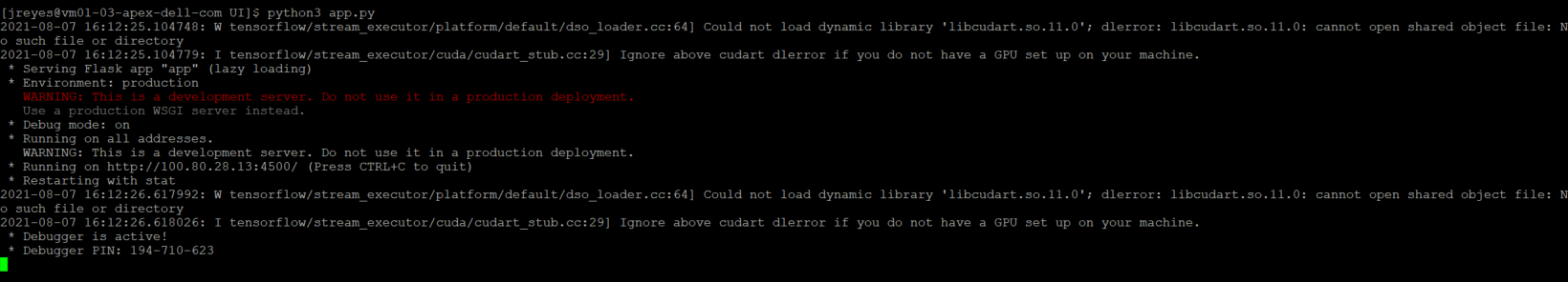
With the app.py program running, I can open a browser, go to the address the UI is running on, localhost:4500, and test it.
Awesome! The UI works as expected.
Using Docker to deploy the application locally
Now I have functioning frontend and backend components. Before I deploy the application in a Docker container, I need to containerize the UI.
This step requires a Dockerfile and a requirements text file. The requirements text file will contain all the dependencies needed to run the Flask web server and our python scripts. More than likely, when you first run the provided python scripts, a modules not found display will appear followed by a prompt asking you to install them on your machine. Typically, you don't want users to log into the container directly and install the dependencies for an application on the fly. Thus, all these dependencies need to be installed when the container is first created, these are defined in this text file.
A Dockerfile is a YAML file that outlines the instructions on how to construct this flask server container. The first line in the YAML file is the python image version, in this case I used a 3.9.6. Docker hub which has several python version images available. Then I need to specify the folder that contains all the python, HTML, and CSS files, and set them as the working directory.
Note: The python scripts must locate our label image text file in this directory and any other files that our code depends on.
Then run a couple of commands in the container: upgrade pip and install the requirements mentioned in the text file. Finally, the entry point, flask run is added.
With a complete Dockerfile, I can run the Docker build command to construct the container, however, I will write a Docker-compose file. This docker-compose file calls the Dockerfile that constructs the flask server and configures the TensorFlow serving image.
In the docker-compose script, I defined some environment variables for the UI and specify the ports for both containers. The containers have to reach each other, which requires me to create a network where both containers will be placed.
Before running the docker-compose file, I must modify the app.py file to make sure it calls the TensorFlow container by name (not localhost). Not changing this value will cause issues because the frontend and the backend containers will be in different pods in Kubernetes.
I must also move the class label text file to the UI folder so that the python scripts can find the text file. To do so, I have to modify the file path in the python script.
I can now execute the Docker-compose file.
$ docker compose up
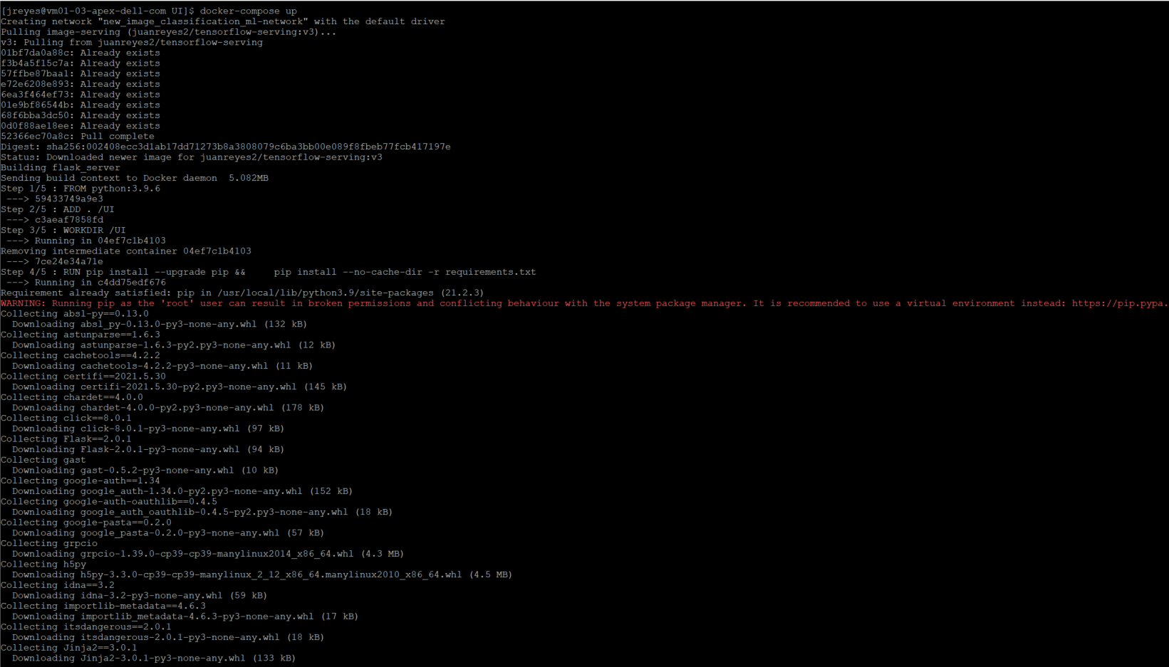
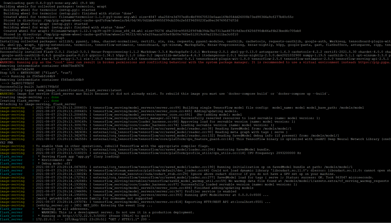
The first time performing this command will take a couple of minutes because it is building the UI container for the first time.
Now that both pods are running, I will navigate to the webserver running on port 5000 and run a few tests to make sure that both ports of the TensorFlow server are responding correctly.
Success!
Note: If modifications are required for the UI container, you will have to flag the docker-compose command with “--build.” Without the flag, Docker will use the existing container found in the local machine.
Deploying the application to the APEX Private/Hybrid with VMware Tanzu
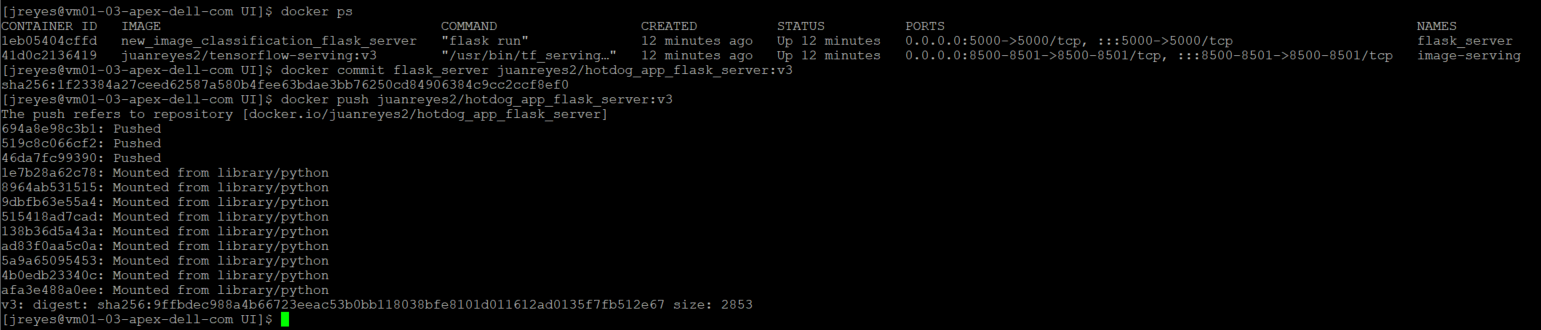
Before I move on to deploying this application to my TKG cluster, I have to save the flask server container image to my Docker Hub registry.
Use the following commands to commit the flask server:
$ docker commit [flask_container_name] [docker_username]/[image_name]:[tag]
$ docker push [docker_username]/ [image_name]:[tag]
Now I can move my application to the APEX Private Tanzu Kubernetes cluster. To do so, I have to log in to my TKG cluster.
$ kubectl vsphere login --vsphere-username [user] --server=[IP/DNS] --insecure-skip-tls-verify=true --tanzu-kubernetes-cluster-namespace [namespace_name] --tanzu-kubernetes-cluster-name [cluster_name]
To deploy my application to my Kubernetes cluster requires a Kubernetes YAML file that defines the various components of the application. Thankfully, there is a tool, Kompose, that translates a docker-compose file into Kubernetes resources.
Use the following command to install the tool in a CentOS VM:
$ sudo yum -y install kompose
Once installed, I can use the tool with the following command:
$ kompose --file [docker-compose file] convert
Each resource defined in the docker-compose file will generate its own individual YAML file.
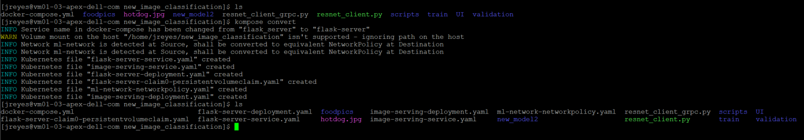
For simplicity, I decided to add all the resources into one YAML file. Now I can call the YAML file and deploy the components of my application:
$ kubectl apply -f [YAML_file(s)]
After a successful deployment, I can view the pods and the services that Kubernetes created.
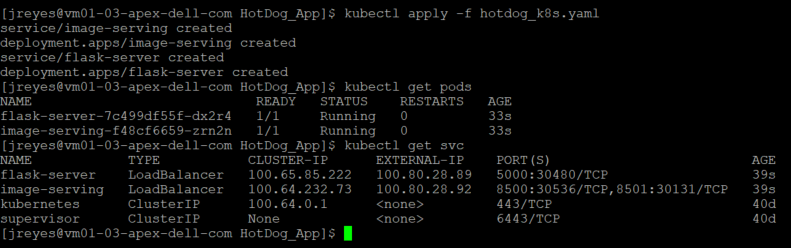
Note: I don't need an external IP for the TensorFlow serving component, but I had it on for debugging purposes. The label “type” in the service definition can be deleted or explicitly say ClusterIP instead loadbalancer.
I will test the application by going to the external IP address that the load balancer assigned to the flask server.
Note: In this APEX Private environment I am using HAProxy as the load balancer for Tanzu workloads. If you are running an older version of the VMware HAProxy ova (<0.1.8), then you have to add the "proto h2" flag to the HAProxy config file. This is required because the gRPC calls would drop intermittently without the flag since HAProxy didn't handle gRPC calls properly until later releases. I recommend upgrading the HAProxy appliance to the latest version because this issue is fixed and you don't have to mess with the HAProxy config file.
backend local_node_h2mode httpserver localhost localhost:8080 proto h2
Great! Now I have successfully deployed an image recognition application in APEX Private with VMware Tanzu.
Consistent hybrid cloud offering public and private deployment options
We've reached the end of this walkthrough.
In summary, I deployed a custom TensorFlow model, created a basic frontend to call the model, containerized the frontend, and deployed all the components to APEX Private with VMware Tanzu. VMware Tanzu is available in all the major public cloud solutions and this provides users with the flexibility to move workloads between cloud providers.
This application can now be deployed to the public cloud or migrated from APEX Private Cloud services. APEX Private/Hybrid Cloud services provides a powerful space for modern application development.
Note: If you want to deploy the components of this application to a public cloud, I recommend similar specs of the Kubernetes cluster and developer machine so that everything runs smoothly. Remember to turn off or delete all the components after you complete the project, to avoid unwanted charges.
In a future blog, I will instrument Knative, a serverless framework, and demonstrate how it works in APEX Private Cloud. After that, I will also have a write up on how to migrate your workloads between APEX Cloud services and other public cloud providers.
That's all, folks.
Author Information
Juan Carlos Reyes
Linkedin: https://www.linkedin.com/in/juancreyes1/

Using HashiCorp Packer in Dell APEX Private Cloud
Wed, 01 Mar 2023 16:42:16 -0000
|Read Time: 0 minutes
Throughout the lifespan of a project, infrastructure engineers can spend hours redeploying virtual machines with the proper configurations, such as for a VDI project in which each team needs a specific configuration. The infrastructure team might have a base image template and customize it for each group. That means booting the base virtual machine, configuring it, and saving it as a newly configured template. Rinse and repeat for each team’s requirements, and it can mean a lot of manual work.
HashiCorp Packer can help create all these virtual machine templates with less manual work. Virtual machine templates help infrastructure administrators standardize their offerings and speed delivery. There are multiple ways to create a template, from manually to a full CI/CD pipeline. In this blog, we will create a SLES 15 SP4 golden image for a Dell APEX Private Cloud environment using HashiCorp Packer. Packer is an open-source tool for creating templates for virtual machines, servers, or hard disk drives (golden images). We’ll design this template to work with Dell APEX Data Storage Services, SUSE RKE2, and Rancher. Within Rancher, we can use this template to deploy downstream clusters using vSphere as the provider.
There are a few prerequisites. We’ll need:
- To install Packer on our workstation
- A SLES 15 SP4 image
- A SLES15 license
- A DHCP network configured in the Dell APEX Private Cloud environment
Plenty of GitHub repositories have Packer templates to get users started. I forked the David-VTUK repo and used it as my starting point. This SLES 15 template works great for an RKE deployment. However, this same template wouldn’t work for an RKE2 deployment, maybe because some packages included (or excluded) in this image conflict with RKE2.
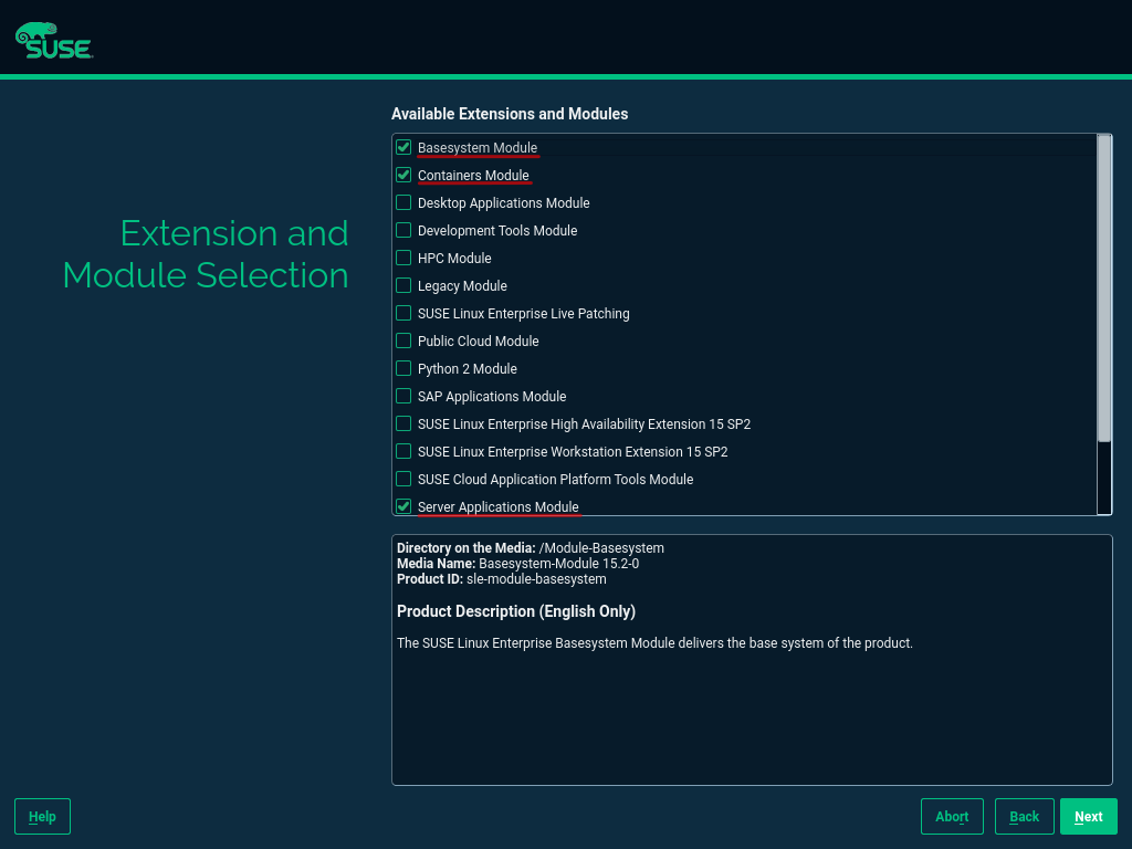
I started by manually creating a virtual machine with SLES 15 SP4 installed, then verified that RKE2 could be installed. (This document has many steps I followed to configure this image.) The only added extension in the configuration was the public cloud module.
After installing SLES 15 SP4, I booted up the virtual machine and installed the cloud-init and open-iscsi services as root.
sudo -i
zypper addrepo https://download.opensuse.org/repositories/Cloud:Tools/SLE_15_SP4/Cloud:Tools.repo
zypper refresh
zypper install cloud-init
zypper install open-iscsi
Cloud-init is required to automate Rancher downstream RKE2 clusters. Open-iscsi allows the image to use Dell APEX Data Storage Services (ADSS) for external storage. In a SUSE Rancher cluster, it is useful for persistent volumes. Make sure to disable the AppArmor and Firewalld services.
Note: The open-iscsi package can be installed as part of the cloud-config setup later on, so we can skip this part.
With the manual image appropriately configured, I used AutoYast to create a new autoinst.xml file. I compared this new file with the autoinst.xml file from the original repo and added the new packages and services that were found on the new autoinst.xml file to the original file.
Now. with an autoinst.xml file compatible with an RKE2 cluster, I ran the Packer script from the GitHub repo to create the new virtual machine template. Don’t forget to modify the variables.json file with the Dell APEX Private Cloud credentials and add the SLES 15 SP4 image to the working directory. The entire creation process takes about 10 minutes to complete.
There you have it, short and sweet. Packer with Dell APEX Private Cloud services is simple, and you can use existing vSphere Packer scripts within APEX Private Cloud.
Note: SUSE recently made available a SLES 15 image with cloud-init enabled. With this new image, creating a template is easier because it only requires spinning up a VM and creating a template inside vCenter. However, Packer makes life easier with specific VM configurations and software installation.
Resources
- Packer Download
- David-VTUK Github Repo
- SLES 15 Configuration Documentation
- AutoYast Documentation
Author: Juan Carlos Reyes, Senior Engineer

Using Terraform to Deploy SUSE Rancher in an APEX Private Cloud Environment
Fri, 03 Feb 2023 11:39:04 -0000
|Read Time: 0 minutes
Automating deployments and managing hardware through code is a beautiful thing. Not only does it free up time, it also enables environment standardization. Infrastructure as Code (IaC) manages and provides an infrastructure through machine-readable definition files rather than manual processes.
In this blog, I demonstrate how to use HashiCorp’s Terraform, a popular open-source Infrastructure-as-Code software tool, in an APEX Private Cloud environment to deploy a fully functional SUSE Rancher cluster. By doing so, infrastructure engineers can set up environments for developers in a short time. All of this is accomplished by leveraging vSphere, Rancher, and standard Terraform providers.
Note: The PhoenixNAP GitHub served as the basis for this deployment.
Pre-requisites
In this blog, we assume that the following steps have been completed:
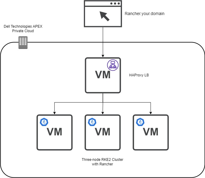
- Network – This is a three-node RKE2 cluster and an optional HAProxy load balancer. Assign three IPs and DNS names for the RKE2 nodes and the same for the single load balancer.
- Virtual Machine Gold Image – This virtual machine template will be the basis for the RKE2 nodes and the load balancer. To create a SLES 15 SP4 template with the required add-ons, see the blog Using HashiCorp Packer in Dell APEX Private Cloud.
- Admin Account – Have a valid vCenter account with enough permissions to create and provision components.
- Here is the GitHub repo with all the files and templates to follow along. Using Terraform, here are the files used to provision Rancher:
- Main.tf file – Defines how secrets, tokens, and certificates are stored and defined in the variables.tf file. This file provides the steps for providers and resources to create the vSphere infrastructure and the commands to deploy provisioners. This is where the Rancher integration is outlined.
- Versions.tf – Specifies which version of Terraform, Rancher, and vSphere on which providers are required to run code that contains no syntax or fatal errors.
- Variables.tf – This file can be used for defining defaults for certain variables. It includes CPU, memory, and vCenter information.
- Templates Folder - During the RKE2 clustering, we require a configuration YAML file that contains the RKE2 Token. This folder stores Terraform’s templates that are used to create the RKE2 configuration files. These files contain Subject Alternative Name (SAN) information and the secret required for subsequent nodes to join the cluster. There is a method to obfuscate the configuration file in a template format, making it more secure when uploading the code to a GitHub repo.
- HAProxy Folder – This folder contains the certificate privacy enhanced mail (PEM) file, key, and configuration file for the HAProxy load balancer.
- Files folder – The configuration files are stored after being created from the templates. You also find the scripts to deploy RKE2 and Rancher.
Creating the HAProxy Node
The first virtual machine defined in the Main.tf file is the HAProxy load balancer. The resource “vsphere_virtual_machine” creation has a standard configuration such as assigning memory, CPU, network, and so on. The critical part is when we start provisioning files to the template files. We use file provisioners to add the HAProxy configuration, certificate, and key files to the virtual machine.
Note: HashiCorp recommends using provisioners as a last-resort option. The reason is that they do not track the state of the object that is modifying and require credentials that are exposed if not appropriately handled.
I used the following command to create a valid self-signed certificate in SLES15. The name of the PEM file must be “cacerts.pem” because it is a requirement by Rancher to propagate appropriately.
openssl req -newkey rsa:2048 -nodes -keyout certificate.key -x509 -days 365 -out cacerts.pem -addext "subjectAltName = DNS:rancher.your.domain"
Next, we use a remote execution provisioner that outlines the commands to install and configure HAProxy in the virtual machine:
    inline = [
      "sudo zypper addrepo https://download.opensuse.org/repositories/server:http/SLE_15/server:http.repo",
      "sudo zypper --gpg-auto-import-keys ref",
      "sudo zypper install -y haproxy",
      "sudo mv /tmp/haproxy.cfg /etc/haproxy",
      "sudo mv /tmp/certificate.pem /etc/ssl/",
      "sudo mv /tmp/certificate.pem.key /etc/ssl/",
      "sudo mkdir /run/haproxy/",
      "sudo systemctl enable haproxy",
      "sudo systemctl start haproxy"
    ]
We add a standard OpenSUSE repo with access to the HAProxy binaries that are compatible with SLES15. Next, the HAProxy installation takes place and moves critical files to the correct location. The last couple systemctl commands start the HAProxy service.
Here is the sample HAProxy configuration file:
global
        log /dev/log    daemon
        log /var/log    local0
        log /var/log    local1 notice
        chroot /var/lib/haproxy
        stats socket /run/haproxy/admin.sock mode 660 level admin
        stats timeout 30s
        user haproxy
        group haproxy
        daemon

        # Default SSL material locations
        ca-base /etc/ssl/certs
        crt-base /etc/ssl/private
        maxconn 1024
        # Default ciphers to use on SSL-enabled listening sockets.
        # For more information, see ciphers(1SSL). This list is from:
        # https://hynek.me/articles/hardening-your-web-servers-ssl-ciphers/
         ssl-default-bind-ciphers ECDH+AESGCM:DH+AESGCM:ECDH+AES256:DH+AES256:ECDH+AES128:DH+AES:ECDH+3DES:DH+3DES:RSA+AESGCM:RSA+AES:RSA+3DES:!aNULL:!MD5:!DSS
        ssl-default-bind-options ssl-min-ver TLSv1.2 prefer-client-ciphers
         tune.ssl.default-dh-param 2048
        cpu-map  1 1
        cpu-map  2 2
        cpu-map  3 3
        cpu-map  4 4

defaults
        log     global
        mode    http
        option  httplog
        option   forwardfor
        option  dontlognull
        timeout connect 50000s
        timeout client  50000s
        timeout server  50000s
        retries 4
        maxconn 2000000

frontend www-http
        mode http
        stats enable
        stats uri /haproxy?stats
        bind *:80
        http-request set-header X-Forwarded-Proto http
        option http-server-close
        option forwardfor except 127.0.0.1
        option forwardfor header X-Real-IP
        # MODIFY host
        acl host_rancher hdr(host) -i rancher.apca1.apextme.dell.com
        acl is_websocket hdr(Upgrade) -i WebSocket
        acl is_websocket hdr_beg(Host) -i wss
        use_backend rancher if host_rancher

frontend www-https
        bind *:443 ssl crt /etc/ssl/certificate.pem alpn h2,http/1.1
        option http-server-close
        http-request set-header X-Forwarded-Proto https if { ssl_fc }
        redirect scheme https code 301 if !{ ssl_fc }
        option forwardfor except 127.0.0.1
        option forwardfor header X-Real-IP
        # MODIFY host
        acl host_rancher hdr(host) -i rancher.apca1.apextme.dell.com
        acl is_websocket hdr(Upgrade) -i WebSocket
        acl is_websocket hdr_beg(Host) -i wss
        use_backend rancher if host_rancher

frontend kubernetes
        # MODIFY IP
        bind 100.80.28.72:6443
        option tcplog
        mode tcp
        default_backend kubernetes-master-nodes

frontend supervisor_FE
        # MODIFY IP
        bind 100.80.28.72:9345
        option tcplog
        mode tcp
        default_backend supervisor_BE

backend rancher
        redirect scheme https code 301 if !{ ssl_fc }
        mode http
        balance roundrobin
        option httpchk HEAD /healthz HTTP/1.0
        # MODIFY IPs
        server rke-dev-01 100.80.28.73:80 check
        server rke-dev-02 100.80.28.74:80 check
        server rke-dev-03 100.80.28.75:80 check

backend kubernetes-master-nodes
        mode tcp
        balance roundrobin
        option tcp-check
        # MODIFY IPs
        server rke-dev-01 100.80.28.73:6443 check
        server rke-dev-02 100.80.28.74:6443 check
        server rke-dev-03 100.80.28.75:6443 check

backend supervisor_BE
        mode tcp
        balance roundrobin
        option tcp-check
        # MODIFY IPs
        server rke-dev-01 100.80.28.73:9345 check
        server rke-dev-02 100.80.28.74:9345 check
        server rke-dev-03 100.80.28.75:9345 check
To troubleshoot the configuration file, you can execute the following command:
haproxy -f /path/to/haproxy.cfg -c
Another helpful troubleshooting tip for HAProxy is to inspect the status page for more information about connections to the load balancer. This is defined in the configuration file as stats uri /haproxy?stats. Use a browser to navigate to the page http://serverip/haproxy?stats.
After HAProxy starts successfully, the script deploys the RKE2 nodes. Again, the initial infrastructure configuration is standard. Let’s take a closer look to the files config.yaml and script.sh that are used to configure RKE2. The script.sh file contains the commands that will download and start the RKE2 service on the node. The script.sh file is copied to the virtual machine via the file provisioner and also made executable in the remote-exec provisoner. In a separate file provisioner module, the config.yaml file is moved to a newly created rke2 folder, the default location where the rke2 service looks for such a file.
Here is a look at the script.sh file:
sudo curl -sfL https://get.rke2.io | sudo sh -
sudo systemctl enable rke2-server.service
n=0
until [ "$n" -ge 5 ]
do
   sudo systemctl start rke2-server.service && break  # substitute your command here
   n=$((n+1))
   sleep 60
done
Notice that the start service command is in a loop to ensure that the service is running before moving on to the next node.
Next, we make sure to add the host information of the other nodes to the current virtual machine host file.
The subsequent two nodes follow the same sequence of events but use the config_server.yaml file, which contains the first node’s API address. The final node has an additional step: using the rancher_install.sh file to install Rancher on the cluster.
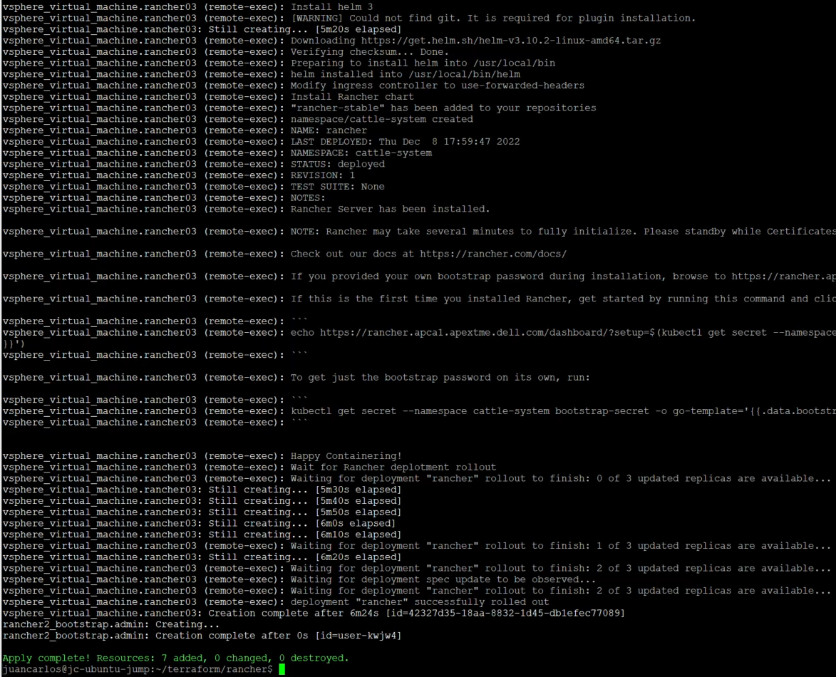
Here is a look at the rancher_install.sh file:
echo "Create ~/.kube"
mkdir -p /root/.kube
echo "Grab kubeconfig"
while [ ! -f /etc/rancher/rke2/rke2.yaml ]
do
  echo "waiting for kubeconfig"
  sleep 2
done
echo "Put kubeconfig to /root/.kube/config"
cp -a /etc/rancher/rke2/rke2.yaml /root/.kube/config
echo "Wait for nodes to come online."
i=0
echo "i have $i nodes"
while [ $i -le 2 ]
do
   i=`/var/lib/rancher/rke2/bin/kubectl get nodes | grep Ready | wc -l`
  echo I have: $i nodes
  sleep 2s
done
echo "Wait for complete deployment of node three, 60 seconds."
sleep 60
echo "Install helm 3"
curl -fsSL -o get_helm.sh https://raw.githubusercontent.com/helm/helm/master/scripts/get-helm-3
chmod 700 get_helm.sh
./get_helm.sh
echo "Modify ingress controller to use-forwarded-headers."
cat << EOF > /var/lib/rancher/rke2/server/manifests/rke2-ingress-nginx-config.yaml
---
apiVersion: helm.cattle.io/v1
kind: HelmChartConfig
metadata:
  name: rke2-ingress-nginx
  namespace: kube-system
spec:
  valuesContent: |-
    controller:
      config:
        use-forwarded-headers: "true"
EOF
echo "Install stable Rancher chart"
helm repo add rancher-stable https://releases.rancher.com/server-charts/stable
/var/lib/rancher/rke2/bin/kubectl create namespace cattle-system
/var/lib/rancher/rke2/bin/kubectl -n cattle-system create secret generic tls-ca --from-file=cacerts.pem=/tmp/cacerts.pem
# Modify hostname and bootstrap password if needed
helm install rancher rancher-stable/rancher \
  --namespace cattle-system \
  --set hostname=rancher.your.domain \
  --set bootstrapPassword=admin \
  --set ingress.tls.source=secret \
  --set tls=external \
  --set additionalTrustedCAs=true \
  --set privateCA=true

/var/lib/rancher/rke2/bin/kubectl -n cattle-system create secret generic tls-ca-additional --from-file=ca-additional.pem=/tmp/cacerts.pem
echo "Wait for Rancher deployment rollout."
/var/lib/rancher/rke2/bin/kubectl -n cattle-system rollout status deploy/rancher
Before the installation begins, there is a step that waits for all the rke2 nodes to be ready. This rancher_install.sh script follows the installation steps from the Rancher website. For this example, we are using an external load balancer. We, therefore, modified the ingress controller to use-forwarded-headers, as stated in the Rancher documentation. The other key parts of this script are the default bootstrap password and the TLS/CA flags assigned in the helm command. To change the administrator password successfully, it must be the same as the password used by the Rancher provider. The TLS and CA flags let the pods know that a self-signed certificate is being used and not to create additional internal certificates.
Note: The wait timers are critical for this deployment because they allow the cluster to be fully available before moving to the next step. Lower wait times can lead to the processes hanging and leaving uncompleted steps.
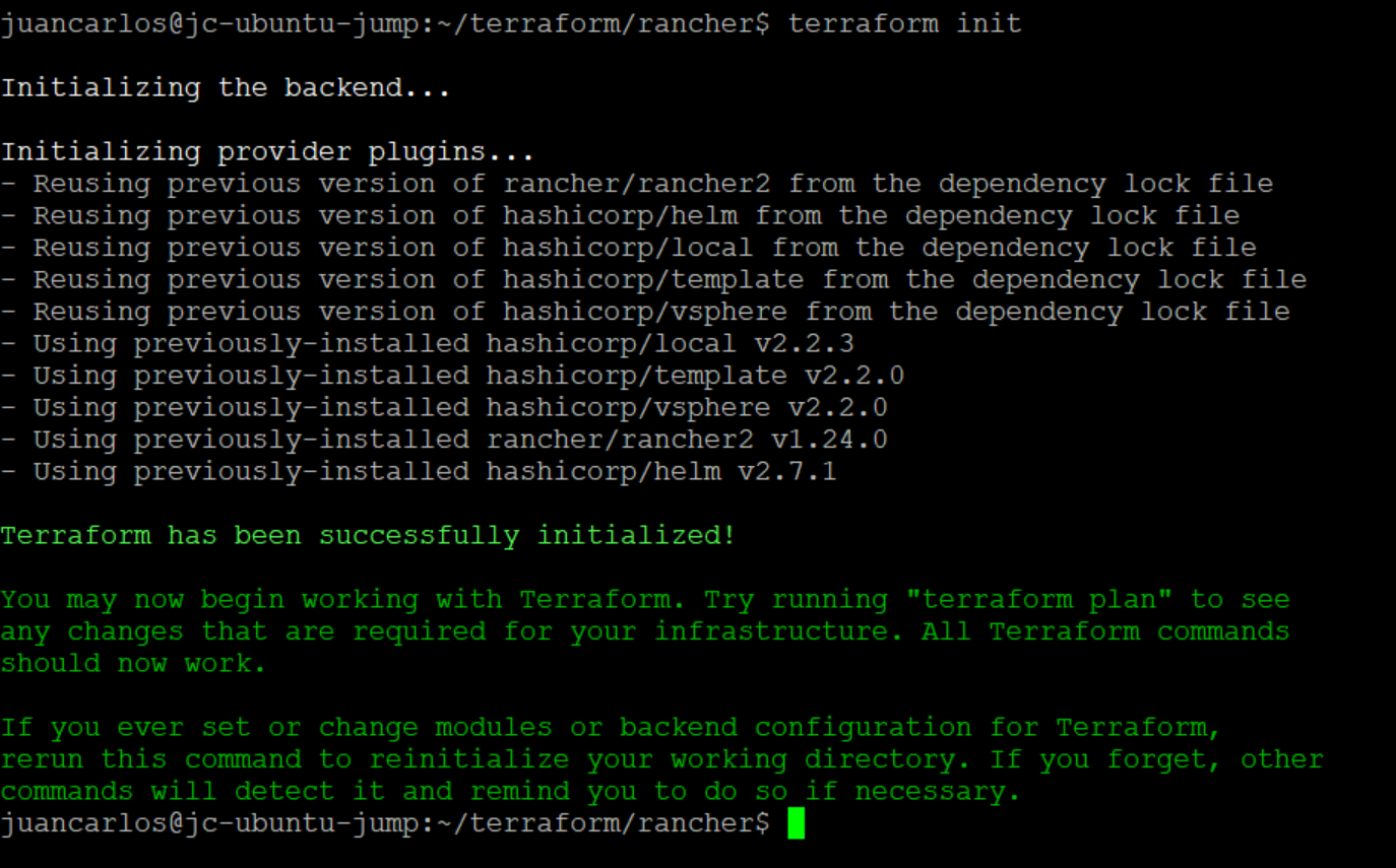
Navigate to the working directory, then use the following command to initialize Terraform:
terraform init
This command verifies that the appropriate versions of the project’s providers are installed and available.
Next, execute the ‘plan’ and ‘apply’ commands.
terraform plan

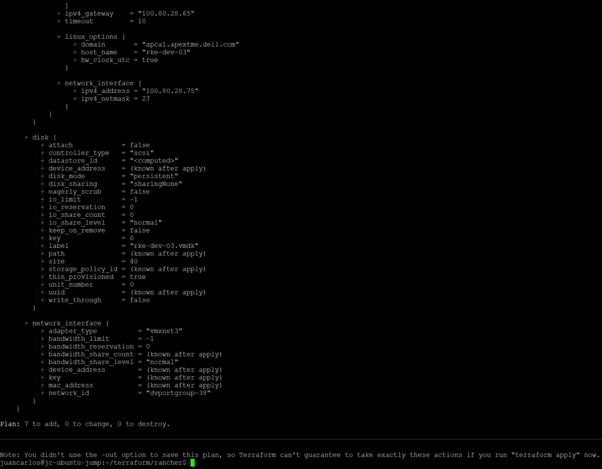
terraform apply –auto-approve

The deployment takes about 15 minutes. After a successful deployment, users can log in to Rancher and deploy downstream clusters (which can also be deployed using Terraform). This project also has a non-HAProxy version if users are interested in that deployment. The main difference is setting up a manual round-robin load balance within your DNS provider.
With this example, we have demonstrated how engineers can use Terraform to set up a SUSE Rancher environment quickly for their developers within Dell APEX Private Cloud.
Author: Juan Carlos Reyes

Using Terraform to Deploy SUSE Rancher in an APEX Private Cloud Environment
Sat, 28 Jan 2023 23:44:51 -0000
|Read Time: 0 minutes
Automating deployments and managing hardware through code is a beautiful thing. Not only does it free up time, it also enables environment standardization. Infrastructure as Code (IaC) manages and provides an infrastructure through machine-readable definition files rather than manual processes.
In this blog, I demonstrate how to use HashiCorp’s Terraform, a popular open-source Infrastructure-as-Code software tool, in an APEX Private Cloud environment to deploy a fully functional SUSE Rancher cluster. By doing so, infrastructure engineers can set up environments for developers in a short time. All of this is accomplished by leveraging vSphere, Rancher, and standard Terraform providers.
Note: The PhoenixNAP GitHub served as the basis for this deployment.
Pre-requisites
In this blog, we assume that the following steps have been completed:
- Network – This is a three-node RKE2 cluster and an optional HAProxy load balancer. Assign three IPs and DNS names for the RKE2 nodes and the same for the single load balancer.
- Virtual Machine Gold Image – This virtual machine template will be the basis for the RKE2 nodes and the load balancer. To create a SLES 15 SP4 template with the required add-ons, see the blog Using HashiCorp Packer in Dell APEX Private Cloud.
- Admin Account – Have a valid vCenter account with enough permissions to create and provision components.
- Here is the GitHub repo with all the files and templates to follow along. Using Terraform, here are the files used to provision Rancher:
- Main.tf file – Defines how secrets, tokens, and certificates are stored and defined in the variables.tf file. This file provides the steps for providers and resources to create the vSphere infrastructure and the commands to deploy provisioners. This is where the Rancher integration is outlined.
- Versions.tf – Specifies which version of Terraform, Rancher, and vSphere on which providers are required to run code that contains no syntax or fatal errors.
- Variables.tf – This file can be used for defining defaults for certain variables. It includes CPU, memory, and vCenter information.
- Templates Folder - During the RKE2 clustering, we require a configuration YAML file that contains the RKE2 Token. This folder stores Terraform’s templates that are used to create the RKE2 configuration files. These files contain Subject Alternative Name (SAN) information and the secret required for subsequent nodes to join the cluster. There is a method to obfuscate the configuration file in a template format, making it more secure when uploading the code to a GitHub repo.
- HAProxy Folder – This folder contains the certificate privacy enhanced mail (PEM) file, key, and configuration file for the HAProxy load balancer.
- Files folder – The configuration files are stored after being created from the templates. You also find the scripts to deploy RKE2 and Rancher.
Creating the HAProxy Node
The first virtual machine defined in the Main.tf file is the HAProxy load balancer. The resource “vsphere_virtual_machine” creation has a standard configuration such as assigning memory, CPU, network, and so on. The critical part is when we start provisioning files to the template files. We use file provisioners to add the HAProxy configuration, certificate, and key files to the virtual machine.
Note: HashiCorp recommends using provisioners as a last-resort option. The reason is that they do not track the state of the object that is modifying and require credentials that are exposed if not appropriately handled.
I used the following command to create a valid self-signed certificate in SLES15. The name of the PEM file must be “cacerts.pem” because it is a requirement by Rancher to propagate appropriately.
openssl req -newkey rsa:2048 -nodes -keyout certificate.key -x509 -days 365 -out cacerts.pem -addext "subjectAltName = DNS:rancher.your.domain"
Next, we use a remote execution provisioner that outlines the commands to install and configure HAProxy in the virtual machine:
    inline = [
      "sudo zypper addrepo https://download.opensuse.org/repositories/server:http/SLE_15/server:http.repo",
      "sudo zypper --gpg-auto-import-keys ref",
      "sudo zypper install -y haproxy",
      "sudo mv /tmp/haproxy.cfg /etc/haproxy",
      "sudo mv /tmp/certificate.pem /etc/ssl/",
      "sudo mv /tmp/certificate.pem.key /etc/ssl/",
      "sudo mkdir /run/haproxy/",
      "sudo systemctl enable haproxy",
      "sudo systemctl start haproxy"
    ]
We add a standard OpenSUSE repo with access to the HAProxy binaries that are compatible with SLES15. Next, the HAProxy installation takes place and moves critical files to the correct location. The last couple systemctl commands start the HAProxy service.
Here is the sample HAProxy configuration file:
global
        log /dev/log    daemon
        log /var/log    local0
        log /var/log    local1 notice
        chroot /var/lib/haproxy
        stats socket /run/haproxy/admin.sock mode 660 level admin
        stats timeout 30s
        user haproxy
        group haproxy
        daemon

        # Default SSL material locations
        ca-base /etc/ssl/certs
        crt-base /etc/ssl/private
        maxconn 1024
        # Default ciphers to use on SSL-enabled listening sockets.
        # For more information, see ciphers(1SSL). This list is from:
        # https://hynek.me/articles/hardening-your-web-servers-ssl-ciphers/
         ssl-default-bind-ciphers ECDH+AESGCM:DH+AESGCM:ECDH+AES256:DH+AES256:ECDH+AES128:DH+AES:ECDH+3DES:DH+3DES:RSA+AESGCM:RSA+AES:RSA+3DES:!aNULL:!MD5:!DSS
        ssl-default-bind-options ssl-min-ver TLSv1.2 prefer-client-ciphers
         tune.ssl.default-dh-param 2048
        cpu-map  1 1
        cpu-map  2 2
        cpu-map  3 3
        cpu-map  4 4

defaults
        log     global
        mode    http
        option  httplog
        option   forwardfor
        option  dontlognull
        timeout connect 50000s
        timeout client  50000s
        timeout server  50000s
        retries 4
        maxconn 2000000

frontend www-http
        mode http
        stats enable
        stats uri /haproxy?stats
        bind *:80
        http-request set-header X-Forwarded-Proto http
        option http-server-close
        option forwardfor except 127.0.0.1
        option forwardfor header X-Real-IP
        # MODIFY host
        acl host_rancher hdr(host) -i rancher.apca1.apextme.dell.com
        acl is_websocket hdr(Upgrade) -i WebSocket
        acl is_websocket hdr_beg(Host) -i wss
        use_backend rancher if host_rancher

frontend www-https
        bind *:443 ssl crt /etc/ssl/certificate.pem alpn h2,http/1.1
        option http-server-close
        http-request set-header X-Forwarded-Proto https if { ssl_fc }
        redirect scheme https code 301 if !{ ssl_fc }
        option forwardfor except 127.0.0.1
        option forwardfor header X-Real-IP
        # MODIFY host
        acl host_rancher hdr(host) -i rancher.apca1.apextme.dell.com
        acl is_websocket hdr(Upgrade) -i WebSocket
        acl is_websocket hdr_beg(Host) -i wss
        use_backend rancher if host_rancher

frontend kubernetes
        # MODIFY IP
        bind 100.80.28.72:6443
        option tcplog
        mode tcp
        default_backend kubernetes-master-nodes

frontend supervisor_FE
        # MODIFY IP
        bind 100.80.28.72:9345
        option tcplog
        mode tcp
        default_backend supervisor_BE

backend rancher
        redirect scheme https code 301 if !{ ssl_fc }
        mode http
        balance roundrobin
        option httpchk HEAD /healthz HTTP/1.0
        # MODIFY IPs
        server rke-dev-01 100.80.28.73:80 check
        server rke-dev-02 100.80.28.74:80 check
        server rke-dev-03 100.80.28.75:80 check

backend kubernetes-master-nodes
        mode tcp
        balance roundrobin
        option tcp-check
        # MODIFY IPs
        server rke-dev-01 100.80.28.73:6443 check
        server rke-dev-02 100.80.28.74:6443 check
        server rke-dev-03 100.80.28.75:6443 check

backend supervisor_BE
        mode tcp
        balance roundrobin
        option tcp-check
        # MODIFY IPs
        server rke-dev-01 100.80.28.73:9345 check
        server rke-dev-02 100.80.28.74:9345 check
        server rke-dev-03 100.80.28.75:9345 check
To troubleshoot the configuration file, you can execute the following command:
haproxy -f /path/to/haproxy.cfg -c
Another helpful troubleshooting tip for HAProxy is to inspect the status page for more information about connections to the load balancer. This is defined in the configuration file as stats uri /haproxy?stats. Use a browser to navigate to the page http://serverip/haproxy?stats.
After HAProxy starts successfully, the script deploys the RKE2 nodes. Again, the initial infrastructure configuration is standard. Let’s take a closer look to the files config.yaml and script.sh that are used to configure RKE2. The script.sh file contains the commands that will download and start the RKE2 service on the node. The script.sh file is copied to the virtual machine via the file provisioner and also made executable in the remote-exec provisoner. In a separate file provisioner module, the config.yaml file is moved to a newly created rke2 folder, the default location where the rke2 service looks for such a file.
Here is a look at the script.sh file:
sudo curl -sfL https://get.rke2.io | sudo sh -
sudo systemctl enable rke2-server.service
n=0
until [ "$n" -ge 5 ]
do
   sudo systemctl start rke2-server.service && break  # substitute your command here
   n=$((n+1))
   sleep 60
done
Notice that the start service command is in a loop to ensure that the service is running before moving on to the next node.
Next, we make sure to add the host information of the other nodes to the current virtual machine host file.
The subsequent two nodes follow the same sequence of events but use the config_server.yaml file, which contains the first node’s API address. The final node has an additional step: using the rancher_install.sh file to install Rancher on the cluster.
Here is a look at the rancher_install.sh file:
echo "Create ~/.kube"
mkdir -p /root/.kube
echo "Grab kubeconfig"
while [ ! -f /etc/rancher/rke2/rke2.yaml ]
do
  echo "waiting for kubeconfig"
  sleep 2
done
echo "Put kubeconfig to /root/.kube/config"
cp -a /etc/rancher/rke2/rke2.yaml /root/.kube/config
echo "Wait for nodes to come online."
i=0
echo "i have $i nodes"
while [ $i -le 2 ]
do
   i=`/var/lib/rancher/rke2/bin/kubectl get nodes | grep Ready | wc -l`
  echo I have: $i nodes
  sleep 2s
done
echo "Wait for complete deployment of node three, 60 seconds."
sleep 60
echo "Install helm 3"
curl -fsSL -o get_helm.sh https://raw.githubusercontent.com/helm/helm/master/scripts/get-helm-3
chmod 700 get_helm.sh
./get_helm.sh
echo "Modify ingress controller to use-forwarded-headers."
cat << EOF > /var/lib/rancher/rke2/server/manifests/rke2-ingress-nginx-config.yaml
---
apiVersion: helm.cattle.io/v1
kind: HelmChartConfig
metadata:
  name: rke2-ingress-nginx
  namespace: kube-system
spec:
  valuesContent: |-
    controller:
      config:
        use-forwarded-headers: "true"
EOF
echo "Install stable Rancher chart"
helm repo add rancher-stable https://releases.rancher.com/server-charts/stable
/var/lib/rancher/rke2/bin/kubectl create namespace cattle-system
/var/lib/rancher/rke2/bin/kubectl -n cattle-system create secret generic tls-ca --from-file=cacerts.pem=/tmp/cacerts.pem
# Modify hostname and bootstrap password if needed
helm install rancher rancher-stable/rancher \
  --namespace cattle-system \
  --set hostname=rancher.your.domain \
  --set bootstrapPassword=admin \
  --set ingress.tls.source=secret \
  --set tls=external \
  --set additionalTrustedCAs=true \
  --set privateCA=true

/var/lib/rancher/rke2/bin/kubectl -n cattle-system create secret generic tls-ca-additional --from-file=ca-additional.pem=/tmp/cacerts.pem
echo "Wait for Rancher deployment rollout."
/var/lib/rancher/rke2/bin/kubectl -n cattle-system rollout status deploy/rancher
Before the installation begins, there is a step that waits for all the rke2 nodes to be ready. This rancher_install.sh script follows the installation steps from the Rancher website. For this example, we are using an external load balancer. We, therefore, modified the ingress controller to use-forwarded-headers, as stated in the Rancher documentation. The other key parts of this script are the default bootstrap password and the TLS/CA flags assigned in the helm command. To change the administrator password successfully, it must be the same as the password used by the Rancher provider. The TLS and CA flags let the pods know that a self-signed certificate is being used and not to create additional internal certificates.
Note: The wait timers are critical for this deployment because they allow the cluster to be fully available before moving to the next step. Lower wait times can lead to the processes hanging and leaving uncompleted steps.
Navigate to the working directory, then use the following command to initialize Terraform:
terraform init
This command verifies that the appropriate versions of the project’s providers are installed and available.
Next, execute the ‘plan’ and ‘apply’ commands.
terraform plan
terraform apply –auto-approve
The deployment takes about 15 minutes. After a successful deployment, users can log in to Rancher and deploy downstream clusters (which can also be deployed using Terraform). This project also has a non-HAProxy version if users are interested in that deployment. The main difference is setting up a manual round-robin load balance within your DNS provider.
With this example, we have demonstrated how engineers can use Terraform to set up a SUSE Rancher environment quickly for their developers within Dell APEX Private Cloud.
Author: Juan Carlos Reyes