


The Future of Mobile 5G Radio Networks and Why Dell is Looking Ahead
Download PDFMon, 16 Jan 2023 13:44:28 -0000
|Read Time: 0 minutes
Summary
Communication service providers are envisioning increased demand for mobile services including media and content delivery, mobile gaming, virtual reality and connected vehicles. To satisfy this emerging demand, the buildout of a 5G cellular infrastructure has commenced. This tech note explores how computing platforms could have an integral impact on the future framework of the mobile 5G cellular infrastructure, as well as how the confluence of FPGA accelerator technologies within Edge servers would enhance computing performance to support these radio network workloads.
The Transition from 4G to 5G
With mobile technology often substituting as the modern day primary computing resource, the demand for increased mobile services has propelled mobile providers to recognize that 4G LTE mobile infrastructure is no longer adequate. A traditional 4G LTE radio access network diagram is shown below in Figure 1. At the heart of this is the baseband unit (BBU), which provides the backhaul interface to the mobile network core and the front haul interface to the remote radio head (RRH).
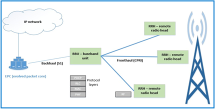
Figure 1: Traditional 4G LTE radio access network infrastructure
One of the obstacles to widespread deployment of new wireless networks is the potential cost of customized equipment. Instead of utilizing standard IT equipment, such as servers or switches, functions in these networks have traditionally been performed by purpose-built devices. Using these proprietary components eliminates a simplified path to increasing performance at a fluid and scalable trajectory.
These insights served as a catalyst to the NFV (Network Functions Virtualization) movement. The goal of NFV is to standardize the telecommunications network infrastructure by steadily introducing an ecosystem of server technology. One of several visions of NFV is to implement the BBU functions using servers. As seen in Figure 2, a C-RAN (Centralized Radio Access Network) can use a Centralized Unit (CU) and distributed Units (DU) for baseband processing.
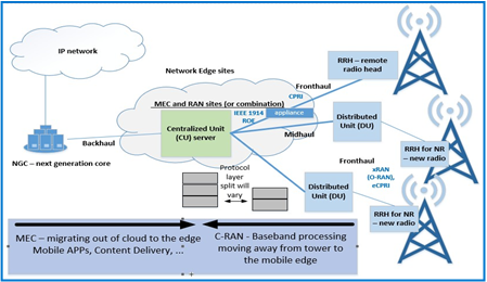
Figure 2: Design concept for 5G; substituting the BBU with C-RAN, composed of a CU (centralized unit) server and multiple DUs (distributed units)
Technical Value Propositions of NFV
Transitioning from a traditional infrastructure to C-RAN would lower the total cost of ownership, improve system capacity utilization, and offer a path to performance improvement at the cell edge. Detailed value propositions explaining the primary design and use case variances between Figures 1 and 2 are listed below:
- The protocol stack implemented by the BBU can be split in different ways between a Centralized Unit (CU) and a Distributed Unit (DU), with different implications and tradeoffs for bandwidth and latency. By moving the Physical (PHY) layer to a DU, bandwidth on the front haul is greatly relieved compared to the Common Public Radio Interference (CPRI) implementation which entails sending time domain radio samples over the interface.
- Because of the various possibilities in splitting the protocol between the CU and DU, emerging standards are evolving to define the new front haul interface. The standard defined by the xRAN consortium, absorbed into the ORAN Alliance, is one example.
- New 5G technology will coexist with 4G LTE radio devices. In places where CPRI is perpetuated with legacy equipment, controllers for these locations will be co-located with controllers for the new technology. One benefit of servers handling this workload is that the same equipment can handle either scenario with different software.
- The development of these centralized sites will provide a means for deployment of Multi-Access Edge Computing (MEC). This will increase the richness and quality of service of the endpoint use cases already cited.
- C-RAN enables Coordinated Multipoint Transmission (CoMP); a technique to increase cell edge coverage and throughput through scheduling. By providing connections to several base stations at once, data can be passed through the least-loaded base stations for better resource utilization. On the receiver side, performance can be increased by using several sites to selectively use the best signal, which can change rapidly due to multipath fading. Also, centralizing mobility and traffic management decisions can lead to fewer handoff failures and less network control signaling, which can also be a potential savings with less need for inter-base station networks.
Despite an array of positive trade-offs, the C-RAN model is still slow to evolve as a mainstream implementation. Of prime importance is the quality of service provided by current and future mobile networks, and with the deployment of servers into these networks, predictable computing performance is required. In most cases, software-based solutions that utilize standard CPUs will be adequate. In some cases, the most efficient use of resources to deliver needed bandwidth and latency may require hardware-assisted acceleration. An example of a computing step performed by the BBU was investigated for suitability in an FPGA (field programmable gate array) peripheral. In house testing at Dell EMC was conducted to quantify the performance gains when using FPGA accelerators for turbo offloads, as shown below:
Performance Gains When Using FPGA for Turbo Offload
Intel’s FlexRAN is a software reference solution that implements Layer 1 of the eNodeB function of an LTE network. At Dell EMC, an end-to-end test platform was created using FlexRAN as the basis for the Layer 1 software of a radio equipment controller baseband unit. The system running FlexRAN was a PowerEdge R740 equipped with a predecessor version of the N3000 network card. For the FPGA offload, patches released in versions 19.03 were introduced along with DPDK patches for BBDev. The complete test apparatus is illustrated in Figure 3:
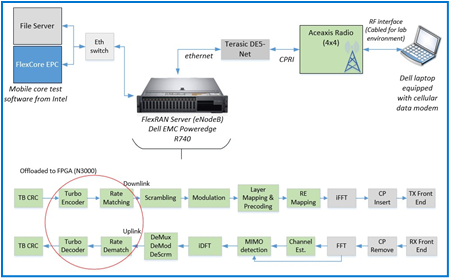
Figure 3: Test apparatus to test CPU utilization with and without offload
As seen in Figure 4, system performance was predictably improved with the FPGA Turbo offload. By enabling system accelerators to perform some of the workload, the CPU experienced nearly half of the cycles required for uplink and downlink layer 1 PHY processing; this implies that the CPU is being utilized twice as much as before. The CPU cycles in the graph were normalized to show the relative quantity used before and after the offload; the exact number of cycles may vary due to several factors; however, it should also be noted that the variation of average to maximum consume cycles in the Turbo Encode operation after the offload was introduced decreased by 86%. The jitter improvement will translate into more predictable latency.
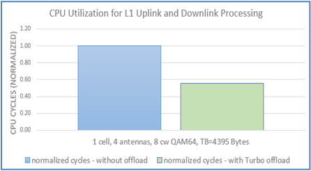
Figure 4: Bar graph demonstrating the improvement of CPU cycles when using FPGA accelerator to offload for various configurations
Conclusion
As the advancement to 5G progresses, it seems undeniable that the improved cost-effectiveness, scalability, flexibility and eventually, performance, of computing platforms will outweigh the trade-offs incorporated with changing an already immense and established infrastructure. Dell EMC is preparing for this inevitable transition from the traditional proprietary Radio Access network (RAN) infrastructure into a NFV server ecosystem by identifying and exploring the benefits, challenges and use cases associated with implementing computing platforms for mobile 5G radio networks.
Related Documents

Understanding the Value of AMDs Socket to Socket Infinity Fabric
Tue, 17 Jan 2023 00:43:22 -0000
|Read Time: 0 minutes
Summary
AMD socket-to-socket Infinity Fabric increases CPU-to-CPU transactional speeds by allowing multiple sockets to communicate directly to one another through these dedicated lanes. This DfD will explain what the socket-to-socket Infinity Fabric interconnect is, how it functions and provides value, as well as how users can gain additional value by dedicating one of the x16 lanes to be used as a PCIe bus for NVMe or GPU use.
Introduction
Prior to socket-to-socket Infinity Fabric (IF) interconnect, CPU-to-CPU communications generally took place on the HyperTransport (HT) bus for AMD platforms. Using this pathway for multi-socket servers worked well during the lifespan of HT, but developing technologies pushed for the development of a solution that would increase data transfer speeds, as well as allow for combo links.
AMD released socket-to-socket Infinity Fabric (also known as xGMI) to resolve these bottlenecks. Having dedicated IF links for direct CPU-to- CPU communications allowed for greater data-transfer speeds, so multi-socket server users could do more work in the same amount of time as before.
How Socket-to-Socket Infinity Fabric Works
IF is the external socket-to-socket interface for 2-socket servers. The architecture used for IF links is a combo of serializer/deserializer (SERDES) that can be both PCIe and xGMI, allowing for sixteen lanes per link and a lot of platform flexibility. xGMI2 is the current generation available and it has speeds that reach up to 18Gbps; which is faster than the PCIe Gen4 speed of 16Gbps. Two CPUs can be supported by these IF links. Each IF lane connects from one CPU IO die to the next, and they are interwoven in a similar fashion, directly connecting the CPUs to one- another. Most dual-socket servers have three to four IF links dedicated for CPU connections. Figure 1 depicts a high- level illustration of how socket to socket IF links connect across CPUs.
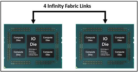
Figure 1 – 4 socket to socket IF links connect two CPUs
The Value of Infinity Fabric Interconnect
Socket to socket IF interconnect creates several advantages for PowerEdge customers:
- Dedicated IF lanes are routed directly from one CPU to the other CPU, ensuring inter-socket communications travel the shortest distance possible
- xGMI2 speeds (18Gbps) exceed the speeds of PCIe Gen4, allowing for extremely fast inter-socket data transfer speeds
Furthermore, if customers require additional PCIe lanes for peripheral components, such as NVMe or GPU drives, one of the four IF links are a cable with a connector that can be repurposed as a PCIe lane. AMD’s highly optimized and flexible link topologies enable sixteen lanes per socket of Infinity Fabric to be repurposed. This means that 2S AMD servers, such as the PowerEdge R7525, have thirty-two additional lanes giving a total of 160 PCIe lanes for peripherals. Figure 2 below illustrates what this would look like:
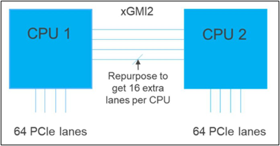
Figure 2 – Diagram showing additional PCIe lanes available in a 2S configuration
Conclusion
AMDs socket-to-socket Infinity Fabric interconnect replaced the former HyperTransport interconnect in order to allow massive amounts of data to travel fast enough to avoid speed bottlenecks. Furthermore, customers needing additional PCIe lanes can repurpose one of the four IF links for peripheral support. These advantages allow AMD PowerEdge servers, such as the R7525, to meet our server customer needs.

Understanding the Value of AMDs Socket to Socket Infinity Fabric
Mon, 16 Jan 2023 13:44:23 -0000
|Read Time: 0 minutes
Summary
AMD socket-to-socket Infinity Fabric increases CPU-to-CPU transactional speeds by allowing multiple sockets to communicate directly to one another through these dedicated lanes. This DfD will explain what the socket-to-socket Infinity Fabric interconnect is, how it functions and provides value, as well as how users can gain additional value by dedicating one of the x16 lanes to be used as a PCIe bus for NVMe or GPU use.
Introduction
Prior to socket-to-socket Infinity Fabric (IF) interconnect, CPU-to-CPU communications generally took place on the HyperTransport (HT) bus for AMD platforms. Using this pathway for multi-socket servers worked well during the lifespan of HT, but developing technologies pushed for the development of a solution that would increase data transfer speeds, as well as allow for combo links.
AMD released socket-to-socket Infinity Fabric (also known as xGMI) to resolve these bottlenecks. Having dedicated IF links for direct CPU-to- CPU communications allowed for greater data-transfer speeds, so multi-socket server users could do more work in the same amount of time as before.
How Socket-to-Socket Infinity Fabric Works
IF is the external socket-to-socket interface for 2-socket servers. The architecture used for IF links is a combo of serializer/deserializer (SERDES) that can be both PCIe and xGMI, allowing for sixteen lanes per link and a lot of platform flexibility. xGMI2 is the current generation available and it has speeds that reach up to 18Gbps; which is faster than the PCIe Gen4 speed of 16Gbps. Two CPUs can be supported by these IF links. Each IF lane connects from one CPU IO die to the next, and they are interwoven in a similar fashion, directly connecting the CPUs to one- another. Most dual-socket servers have three to four IF links dedicated for CPU connections. Figure 1 depicts a high- level illustration of how socket to socket IF links connect across CPUs.
Figure 1 – 4 socket to socket IF links connect two CPUs
The Value of Infinity Fabric Interconnect
Socket to socket IF interconnect creates several advantages for PowerEdge customers:
- Dedicated IF lanes are routed directly from one CPU to the other CPU, ensuring inter-socket communications travel the shortest distance possible
- xGMI2 speeds (18Gbps) exceed the speeds of PCIe Gen4, allowing for extremely fast inter-socket data transfer speeds
Furthermore, if customers require additional PCIe lanes for peripheral components, such as NVMe or GPU drives, one of the four IF links are a cable with a connector that can be repurposed as a PCIe lane. AMD’s highly optimized and flexible link topologies enable sixteen lanes per socket of Infinity Fabric to be repurposed. This means that 2S AMD servers, such as the PowerEdge R7525, have thirty-two additional lanes giving a total of 160 PCIe lanes for peripherals. Figure 2 below illustrates what this would look like:
Figure 2 – Diagram showing additional PCIe lanes available in a 2S configuration
Conclusion
AMDs socket-to-socket Infinity Fabric interconnect replaced the former HyperTransport interconnect in order to allow massive amounts of data to travel fast enough to avoid speed bottlenecks. Furthermore, customers needing additional PCIe lanes can repurpose one of the four IF links for peripheral support. These advantages allow AMD PowerEdge servers, such as the R7525, to meet our server customer needs.