


PowerEdge MX and NVMe/TCP Storage
Download PDF
Introduction
Dell PowerEdge MX was introduced in 2018, and since then Dell Technologies has continued to add new features and functionality to the platform. One such area is the support of NVMe over TCP (NVMe/TCP). As new applications such as Artificial Intelligence and Machine Learning (AI/ML) and the continuing consolidation of virtual workloads demand greater storage performance, NVMe/TCP brings performance improvements over protocols such as iSCSI at a lower price point than compatible Fibre Channel (FC) infrastructure (see Transport Performance Comparison). Incorporating this protocol into storage solution architecture brings new opportunities for higher performance using Ethernet and retiring FC infrastructure.
This tech note describes the architecture required to build PowerEdge MX solutions that use NVMe/TCP, simplifying connectivity to external storage arrays by reducing the physical network and streamlining protocols. It describes the value proposition and technology building blocks and provides high-level configuration examples using VMware.
Technology architecture
The four components of a Dell NVMe/TCP solution are a compute layer with the appropriate host network interface enabled for NVMe/TCP, high-performance 25 GbE or 100 GbE switching network, storage array supporting NVMe/TCP, and, finally, a management application to configure and control access. Dell offers several end-to-end PowerEdge MX base storage solutions that support NVMe/TCP on either 25 GbE or 100 GbE networking. The solutions include PowerEdge servers, PowerSwitch networking, and several Dell storage array products with Dell SmartFabric Storage Software for zoning management.
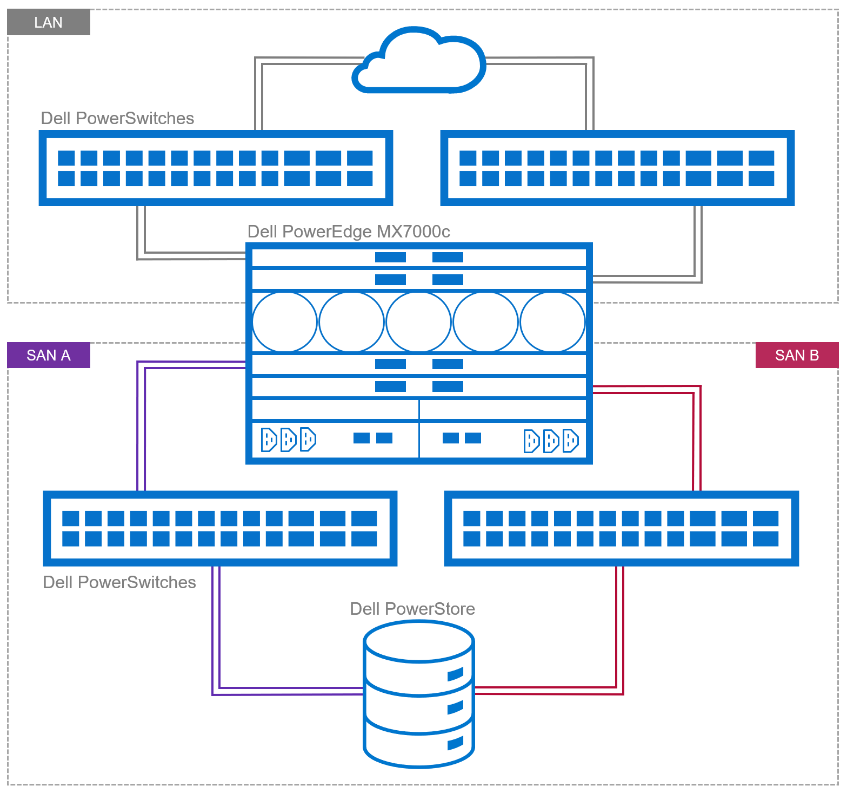
Figure 1. Example of NVMe/TPC SAN and LAN architecture
Dell continues to validate and expand the matrix of supported hardware and software. The document, NVMe/TCP Host/Storage Interoperability Simple Support Matrix, is available on E-Lab Navigator and updated on a regular basis. It includes details about tested configurations and supported storage arrays, such as PowerStore and PowerMax.
Table 1. Example of supported configurations extracted from NVMe/TCP Host/Storage Interoperability Simple Support Matrix
Server | NIC | MX Firmware/ | Storage Array | Boot From San | OS |
MX750c MX760c | Broadcom 57508 dual 100 GbE Mezz card | MX baseline 2.10.00 | PowerMax 2500/8500 OS 10.0.0 / 10.0.1 | No | VMware ESXi 8.0 |
MX760c
| Broadcom 57504 dual 25 GbE Mezz card | MX baseline 2.00.00 | PowerMax 2500/8500 OS 10.0.0 / 10.0.1 | No | VMware ESXi 8.0 |
MX750c MX760c | Broadcom 57508 dual 100 GbE Mezz card | MX baseline 2.10.00 | PowerStore 500T/1000T 3000T/7000T 9000T | No | VMware ESXi 8.0 |
MX760c | Broadcom 57504 dual 25 GbE Mezz card | MX baseline 2.00.00 | PowerStore 500T/1000T 3000T/7000T 9000T | No | VMware ESXi 8.0 |
These are the minimum supported versions. See the Dell support site for the latest approved version.
PowerEdge MX
The 100 GbE mezzanine card was added to the PowerEdge MX compute sled connectivity portfolio in April 2023. The PowerEdge MX offers a choice of both 25 GbE and 100 GbE at the compute sled, with a selection of various networking I/O modules.
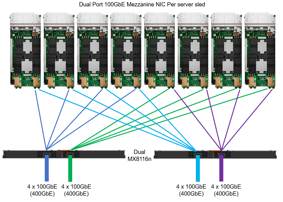
Figure 2. MX chassis 100 GbE architecture
IP switch fabric
NVMe/TCP traffic uses traditional TCP/IP protocols, meaning the network design can be quite flexible. Often, existing networks can be used. The best-practice topology dedicates switches and device ports for storage area network (SAN) traffic only. In Figure 1, local area network (LAN) traffic connects to a pair of switches northbound from Fabric A in the MX chassis. Fabric B connects to dedicated, air-gapped switches to reach the storage array.
For more details about NVMe/TCP networking, see the SmartFabric Storage Software Deployment Guide.
For 25 GbE connectivity, there are a number of options, starting with dual- or quad-port mezzanine cards, with a selection of pass-through or fabric expansion modules or full switches integrated into the PowerEdge MX chassis. For scalability, a pair of external top-of-rack (ToR) switches are implemented for interfacing with the storage array.
For 100 GbE end-to-end connectivity, the MX8116n Fabric Expander Module is a required chassis component for the PowerEdge MX platform. A Z9432F-ON ToR switch is then required for MX8116n connectivity. The Z9432F supports 32 ports x 400 GbE (or 64 ports x 200 GbE using breakouts or 128 ports x multiple interface speeds from 10 GbE to 400 GbE ports using breakouts). So how does the Z9432F-ON work in the MX 100 GbE solution? The 400 GbE ports on the MX8116n connect to ports on the PowerSwitch. The solution scales the network fabric to 14 chassis with 112 PowerEdge MX compute sleds. Each MX7000 chassis uses only 4 x 400 GbE cables, dramatically reducing and simplifying cabling (see Figure 2).
Storage
Taking Dell PowerFlex as an example, NVMe/TCP is supported in the following manner: PowerFlex storage nodes are joined in storage pools. Typically, similar disk types are used within a pool (for example, a pool of NVMe drives or a pool of SAS drives). Volumes are then carved out from that pool, meaning the blocks/chunks/pages of that volume are distributed across every disk in the pool. Regardless of the underlying technology, these volumes can be assigned an NVMe/TCP storage protocol interface ready to be accessed across the network from the hosts accordingly.
Let’s look at another example—this one for Dell PowerStore, which is an all-NVMe flash storage array. A volume can be created and then presented using NVMe/TCP across the network. This allows the performance of the NVMe devices to be shared across the network, offering a truly end-to-end NVMe experience.
NVMe/TCP zoning
An advantage and challenge of Ethernet-based NVMe/TCP is that it scales out from tens to hundreds to thousands of fabric endpoints. This quickly becomes arduous, error prone, and highly cost inefficient. FC excels at automatic endpoint discovery and registration. For NVMe/TCP to be a viable alternative to FC in the data center, it must provide users with FC-like endpoint discovery and registration, and FC-like zoning capabilities. Dell SmartFabric Storage Software (SFSS) is designed to help automate the discovery and registration of hosts and storage arrays using NVMe/TCP.
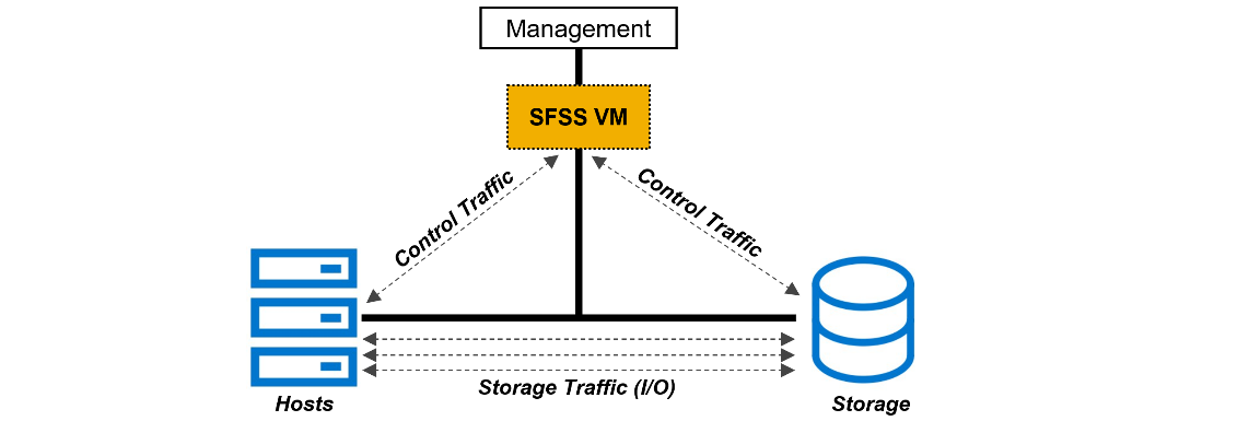
Figure 3. Dell SmartFabric Storage Software (SFSS)
Dell SFSS is a centralized discovery controller (CDC). It discovers, registers, and zones the devices on the NVMe/TCP IP SAN. Customers can control connectivity from a single, centralized location instead of having to configure each host and storage array manually.
VMware support
In October 2021, VMware announced support of the NVMe/TCP storage protocol with the release of VMware vSphere 7 Update 3. VMware has since included support in vSphere 8. It is a simple task to configure an ESXi host for NVMe/TCP. Just select the adapter from the standard list of storage adapters for each required host. Once the adapter is selected in vSphere, the new volume appears automatically as a namespace, assuming access has been granted through SFSS. Any storage volume accessed through NVMe/TCP can be used to create a standard VMFS datastore.
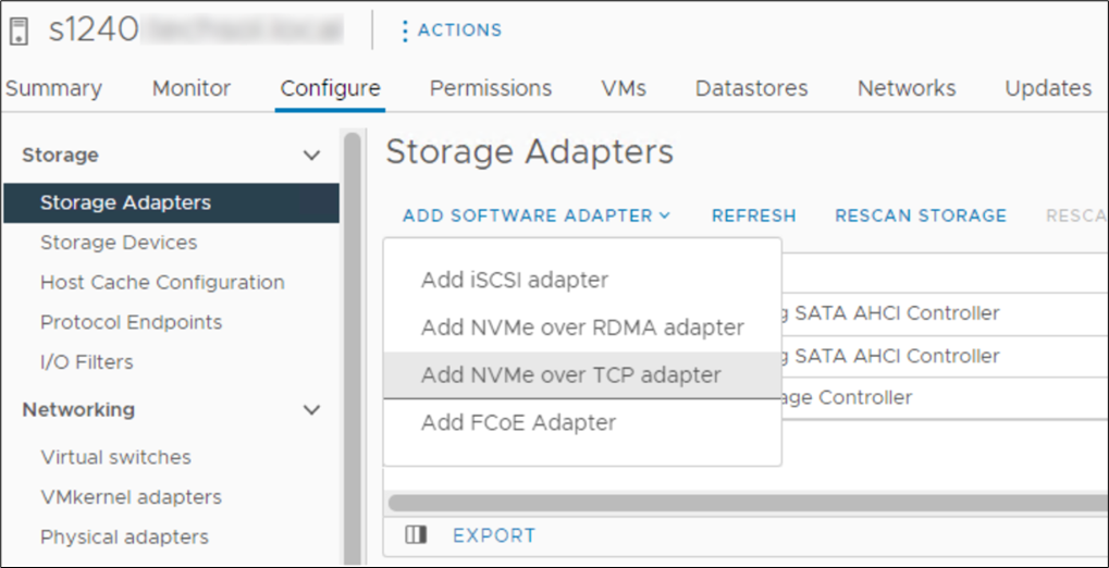 Figure 4. Adding NVMe/TCP adapter in vSphere
Conclusion
NVMe/TCP is now a practical alternative to iSCSI and a replacement to older FC infrastructure. With NVMe/TCP's ability to provide higher IOPS at a lower latency while consuming less CPU than iSCSI, and offering similar performance to FC, NVMe/TCP can provide an immediate benefit. In addition, for customers who have cost constraints or skill shortages, moving from FC to NVMe/TCP is a viable choice. Dell SmartFabric Storage Software is the key component that makes scale-out NVMe/TCP infrastructures manageable. SFSS enables an FC-like user experience for NVMe/TCP. Hosts and storage subsystems can automatically discover and register with SFSS so that a user can create zones and zone groups in a familiar FC-like manner. Using Dell PowerEdge MX as the server compute element dramatically simplifies physical networking so customers can more quickly realize NVMe/TCP storage benefits.
References
- SmartFabric Storage Software Deployment Guide
- PowerEdge MX I/O Guide
- SmartFabric Storage Software: Create a Centralized Discovery Controller for NVMe/TCP (video)
- NVMe/TCP Host/Storage Interoperability (E-Lab Support Matrix)
- Dell Technologies Simple Support Matrices (storage E-Lab Support Matrices portal)
Related Documents

Dell PowerEdge MX7000 and MX760c Liquid Cooling for Maximum Efficiency
Tue, 18 Apr 2023 15:21:16 -0000
|Read Time: 0 minutes
Introduction
The market trend for high-performance servers to support the most demanding workloads has resulted in newer components, especially CPUs, putting more thermal demands on server design than ever before. Dell’s product engineers have brought new thermal innovation and added the choice of direct liquid cooling (DLC) to the PowerEdge MX7000 modular solution.
To maximize performance and cooling efficiency, customers now have the choice of liquid cooling or air cooling to support low-level to mid-level thermal design power (TDP) CPUs when selecting the MX760c with the latest 4th generation Intel® scalable processors. Implementing direct liquid cooling, or DLC, brings numerous benefits, including dramatically reducing the demand for cold air, so saving the costs of chilling, and reducing the power used to distribute cold air in the data center.
Improved efficiency
Thermal conductivity is basically the ability to move heat, and air’s thermal conductivity is much lower than liquid. (The thermal conductivity of air is 0.031; for water, it is a much higher 0.66. These are average values measured in SI units of watts per meter-kelvin [W·m−1·K−1]). This means that DLC-cooled servers can run top-bin, high-TDP CPUs that otherwise could not operate without throttling with air cooling alone. Also, it takes much less energy to pump liquid coolant through a DLC cold-plate loop than moving a high volume of air that might be cooled through a mechanical chiller. That provides an overall energy savings at the rack and data center level that translate to lower operating costs.
While Dell has offered DLC-cooled servers in previous generations, the MX DLC solution is completely new. It uses the latest cold-plate loop design with Leak Sense, a proprietary method of detecting and reporting any coolant leaks in the server node through an iDRAC alert.
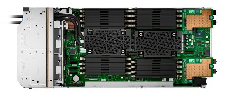
Figure 1. Liquid-cooled PowerEdge MX760c with DLC heat sinks and pipework
The first liquid-cooled Dell server was completed more than ten years ago for a large-scale web company running a dense computer farm. Since then, we have made DLC available on a broad range of PowerEdge platforms, available globally. DLC solutions consist of the server, rack, and rack manifolds to direct coolant to each of the units in a rack, and a Coolant Distribution Unit (CDU). The DLC CDU is connected to the data center water loop and exchanges heat from the rack to the facility water supply. With customers demanding higher levels of performance while also aiming to reduce carbon emissions and energy costs, liquid cooling adoption continues to accelerate. Liquid cooling’s lower energy usage with lower OPEX cost decreases TCO and could produce an ROI within 12 to 24 months depending on the environment.
Table 1. Sample configurations highlighting low fan requirement and power saved by DLC configurations
| Air cooling | Liquid cooling with DLC module | ||||
CPU SKU | 205 W | 225 W | 270 W | 270 W | 300 W | 350 W |
Rear Fan PWR/ Idle CPU Load | 82 W 33% duty | 82 W 33% duty | 82 W 33% duty | 82 W 33% duty | 82 W 33% duty | 82 W 33% duty |
Rear Fan PWR/ 50% CPU Load | 185.7 W 50% duty | 185.7 W 50% duty | 485.3 W 50% duty | 82 W 50% duty | 82 W 33% duty | 82 W 33% duty |
Rear Fan PWR/ 100% Load CPU/MEM/Drive | 1076.8 W 100% duty | 1076.8 W 100% duty | 1076.8 W 100% duty | 111.7 W 39% duty | 111.7 W 39% duty | 111.7 W 39% duty |
Results are based on a four-drive backplane configuration: 4 x 1.92 TB NVMe drives + 24 x 64 GB DDR5 + 2 x 25 Gb mezzanine cards.
Table 2. PowerEdge MX CPU details (offered liquid cooled only)
CPU | TDP | Specifications |
6458Q | 350 W | 4.00 GHz / Max Turbo 3.10 GHz / 60 MB cache / 32 cores |
8458P | 350 W | 2.70 GHz / Max Turbo 3.80 GHz / 82.5 MB cache / 44 cores |
8468 | 350 W | 2.10 GHz / Max Turbo 3.80 GHz / 105 MB cache / 48 cores |
8468V | 330 W | 2.40 GHz / Max Turbo 3.80 GHz / 97.5 MB cache / 48 cores |
8470 | 350 W | 2.00 GHz / Max Turbo 3.80 GHz / 105 MB cache / 52 cores |
8470Q | 350 W | 2.10 GHz / Max Turbo 3.80 GHz / 105 MB cache / 52 cores |
8480+ | 350 W | 2.00 GHz / Max Turbo 3.80 GHz / 105 MB cache / 56 cores |
A liquid cooling solution is limited to a four-drive backplane, E3.S backplane, or diskless configuration. A liquid cooling solution can be provided for all CPU SKUs to support various performance requirements.
Customers can monitor and manage server and chassis power plus thermal data. This information, supplied by the MX chassis and iDRACs, is collected by OpenManage Power Manager and can be reported per individual server, rack, row, and data center. This data can be used to review server power efficiency and locate thermal anomalies such as hotspots. Power Manager also offers additional features, including power capping, carbon emission calculation, and leak detection alert with action automation.
Total solution with direct liquid cooling
The MX760c uses a passive cold-plate loop with supporting liquid cooling infrastructure to capture and remove the heat from the two CPUs. The following image highlights the elements in a complete DLC solution. While customers must provide a facility water connection, a service partner or infrastructure specialist typically provides the remaining solution pieces.
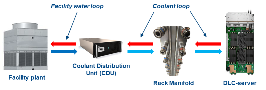
Figure 2. DLC solution elements
Dell customers can now benefit from a pre-integrated DLC rack solution for MX that eliminates the complexity and risk associated with correctly selecting and installing these pieces. The DLC3000 rack solution for MX includes a rack, customer MX rack manifold, in-rack CDU, and each MX chassis and DLC-enabled compute node pre-installed and tested. The rack solution is then delivered to the customer’s data center floor, where the Dell services team connects the rack to facility water and ensures full operation. Finally, Dell ProSupport maintenance and warranty coverage backs everything in the rack to make the whole experience as simple as possible.
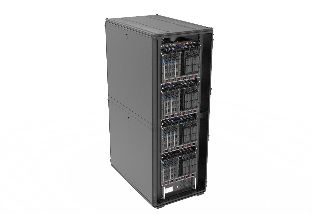
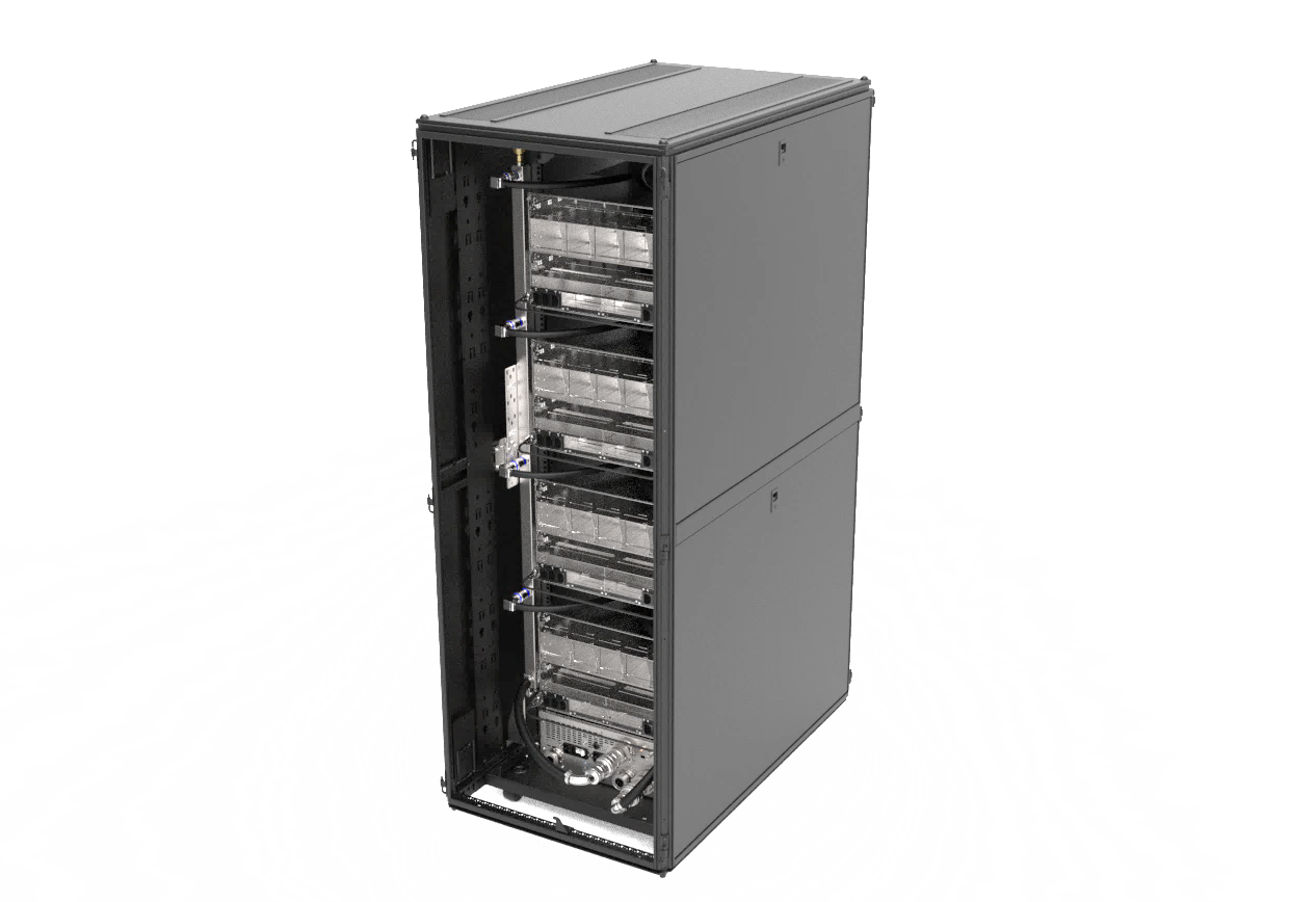
Figure 3. DLC3000 MX rack solution (front and rear views)
Moreover, with the DLC solution, the pre-integrated rack can support up to four MX chassis and 32 compute sleds. With top-bin 350 W Xeon Gen 4 CPUs, that translates to over 22 kW of CPU power captured to the DLC cooling solution. It is a major leap in capability and performance, now available for Dell customers.
Conclusion
As Dell offers the 4th generation Intel CPU in air-cooled and liquid-cooled configurations for use with the PowerEdge MX, customers need to review the choice between traditional air cooling and DLC, and understand the benefits of both to make an informed decision. Organizations need to consider server workload demands, capital expenditures (CAPEX) plus operating expense (OPEX), cost of power, and cost of cooling to understand the full life-cycle costs and determine whether air cooling or DLC provides a better TCO.
References
- Tech Talk Video: MX760c DLC walkthrough
- Unlock New MX CPU and Storage Configurations with a Thermally Optimized Air-Cooled Chassis
- The Future of Server Cooling—Part 1. The History of Server and Data Center Cooling Technologies
- Dell PowerEdge MX760c Technical Guide

Reference Architecture: GPU Acceleration for Dell PowerEdge MX7000
Tue, 26 Sep 2023 16:34:19 -0000
|Read Time: 0 minutes
Summary
Many of today’s most demanding applications can make use of GPU acceleration. Liqid partnered with Dell Technologies, to enable the rapid and dynamic provisioning of PCIe GPUs, as well as FPGA, and NVMe to Dell PowerEdge MX7000 compute sleds. The goal being to ensure that workload performance needs are met for the most accelerator hungry applications.
Background
The Dell PowerEdge MX7000 Modular Chassis simplifies the deployment and management of today’s most challenging workloads by allowing IT administrators to dynamically assign, move, and scale shared pools of compute, storage, and networking resources. It provides IT administrators the ability to deliver fast results, eliminating managing and reconfiguring infrastructure, to meet the ever-changing needs of their end users. For compute intensive AI-driven compute environments and high-value applications, Liqid Matrix software enables the ability to add physical GPUs on-demand to the PowerEdge MX7000.
GPU acceleration for PowerEdge MX7000
The following figure shows the essential MX7000 GPU expansion components:
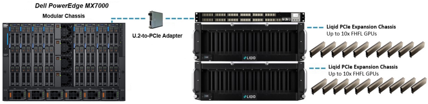
Figure 1. Deploying GPU into a PowerEdge MX7000
Liqid SmartStack Composable Systems for PowerEdge MX7000
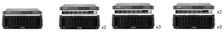
Liqid SmartStacks are fully validated Liqid composable solutions designed to meet your most challenging GPU requirements. Available in four sizes, with a maximum capacity of 30 GPUs and 16 servers per system, each SmartStack includes everything you need to deploy GPUs to MX7000 systems.
Liqid SmartStack 4410 Series Technical Specifications
Table 1. Liqid SmartStack Solutions
| SmartStack 10 | SmartStack 20 | SmartStack 30 | SmartStack 30+ |
Description | 10 GPU / 4 Host Capacity | 20 GPU / 8 Host Capacity | 30 GPU / 6 Host Capacity | 30 GPU / 16 Host Capacity |
Supported Device Types | GPU, NVMe, FPGA, DPU | GPU, NVMe, FPGA, DPU | GPU, NVMe, FPGA, DPU | GPU, NVMe, FPGA, DPU |
Max Devices | 10x Full-height, full-length (FHFL) 10.5”, dual-slot | 20x Full-height, full-length (FHFL) 10.5”, dual-slot | 30x Full-height, full-length (FHFL) 10.5”, dual-slot | 30x Full-height, full-length (FHFL) 10.5”, dual-slot |
Max Hosts Supported | 4x Host Servers | 8x Host Servers | 6x Host Servers | 16x Host Servers |
Max Composed Devices Per Host | 4x Devices | 4x Devices | 4x Devices | 4x Devices |
PCIe Expansion Chassis | 1x Liqid EX-4410 PCIe Gen4 | 2x Liqid EX-4410 PCIe Gen4 | 3x Liqid EX-4410 PCIe Gen4 | 3x Liqid EX-4410 PCIe Gen4 |
PCIe Fabric Switch | None | 1x 48 Port | 1x 48 Port | 2x 48 Port |
PCIe Host Bus Adapter | PCIe Gen3 x4 Per Compute Sled (1 or more) | PCIe Gen3 x4 Per Compute Sled (1 or more) | PCIe Gen3 x4 Per Compute Sled (1 or more) | PCIe Gen3 x4 Per Compute Sled (1 or more) |
Rack Units | 5U | 10U | 14U | 15U |
Composable Devices | Go to liqid.com/resources/library, for a current hardware compatibility list of composable PCIe devices | |||
 Implementing GPU expansion for MX
GPUs are installed into the PCIe expansion chassis. Next, U.2 to PCIe Gen3 adapters are added to each compute sled that requires GPU acceleration. They are then connected to the expansion chassis (Figure 1). Liqid Command Center software enables discovery of all GPUs, making them ready to be added to the server over native PCIe.
FPGA and NVMe storage can also be added to compute nodes in tandem. This PCIe expansion chassis and software are available from Dell.
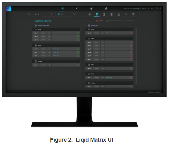
Software-defined GPU deployment
Liqid Matrix software enables the dynamic allocation of GPUs to MX compute sleds at the bare metal level (GPU hot plug supported) via software composability. Up to 4 GPUs can be composed to a single compute sled, using Liqid UI or RESTful API, to meet end user workload requirements. To the operating system, the GPUs are presented as local resources directly connected to the MX compute sled over PCIe (Figure 2). All operating systems are supported including Linux, Microsoft Windows, and VMware ESXi. As workload needs change, using management software to add or remove resources, such as GPU, NVMe SSD and FPGA on the fly.
Enabling GPU Peer-2-Peer capability
A fundamental capability of this solution is the ability for RDMA Peer-2-Peer between GPU devices. Direct RDMA transfers have a massive impact on both throughput and latency for the highest performing GPU-centric applications. Up to 10x improvement in performance has been achieved with RDMA Peer-2-Peer enabled. The following figure provides an overview of how PCIe Peer-2-Peer works (Figure 3).
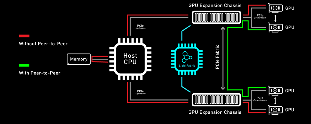
Figure 3. Peer-2-Peer performance
Bypassing the x86 processor, and enabling direct RDMA communication between GPUs, unlocks a dramatic improvement in bandwidth, and a reduction in latency. This chart outlines the performance expected for GPUs that are composed to a single node with GPU RDMA Peer-2-Peer enabled (Table 2).
Table 2. Peer-2-Peer Performance Comparison
| Peer-to-Peer Disabled | Peer-to-Peer Enabled | Improvement |
Bandwidth | 8.6 GB/s | 25.0 GB/s | 3X More Bandwidth |
Latency | 33.7 µs | 3.1 µs | 11X Lower Latency |
Application Performance
Scalable GPU performance is critical for successful outcomes. Tables 4 and 5 present a performance comparison of the Dell MX705c Compute Sled configured with varying numbers of NVIDIA A100 GPUs (1x, 2x, 3x, and 4x) in two different precisions: FP16 and FP32. These results indicate near-linear growth scale.
Table 3. FP16 GPU performance – MX7000 with NVIDIA A100 GPUs, P2P enabled
FP16 | BERT-Base | BERT-Large | GNMT | NCF | ResNet-50 | Tacotron 2 | Transformer-XL Base | Transformer-XL Large | WaveGlow |
1x A100 | 374 | 119 | 187,689 | 37,422,425 | 1,424 | 37,047 | 37,044 | 16,407 | 198,005 |
2x A100 | 638 | 157 | 240,368 | 68,023,242 | 2,627 | 72,631 | 73,661 | 32,694 | 284,709 |
3x A100 | 879 | 208 | 313,561 | 85,030,276 | 3,742 | 87,409 | 102,121 | 45,220 | 376,094 |
4x A100 | 1,088 | 256 | 379,515 | 98,740,107 | 4,657 | 112,282 | 129,336 | 58,503 | 460,793 |
Table 4. FP32 GPU performance – MX7000 with NVIDIA A100 GPUs, P2P enabled
FP32 | BERT-Base | BERT-Large | GNMT | NCF | ResNet-50 | Tacotron 2 | Transformer-XL Base | Transformer-XL Large | WaveGlow |
1x A100 | 184 | 55 | 100,612 | 24,117,691 | 891 | 36,953 | 24,394 | 10,520 | 198,237 |
2x A100 | 283 | 66 | 115,903 | 38,107,456 | 1,610 | 72,218 | 50,108 | 20,941 | 284,047 |
3x A100 | 380 | 88 | 149,359 | 47,133,830 | 2,257 | 84,735 | 66,869 | 28,748 | 370,425 |
4x A100 | 464 | 108 | 180,022 | 57,539,993 | 2,840 | 104,398 | 93,394 | 35,927 | 460,492 |
Conclusion
Liqid composable GPUs for the Dell PowerEdge MX7000 and other PowerEdge rack mount servers unlocks the ability to manage the most demanding workloads in which accelerators are required for both new and existing deployments. Liqid collaborated with Dell Technologies Design Solutions to accelerate applications through the addition of GPUs to the Dell MX compute sleds over PCIe.
Learn more | See a demo | Get a quote
This reference architecture is available as part of the Dell Technologies Design Solutions. To learn more, contact a Design Expert today https://www.delltechnologies.com/en-us/oem/index2.htm#open-contact-form.