


Should Side Vents Be Used in Server Cooling?
Download PDFSat, 27 Jul 2024 15:19:45 -0000
|Read Time: 0 minutes
Summary
Dell Technologies supports high performance components while maintaining air cooling as a viable option for customers. Benchtop testing can vary greatly from real deployment environments with potentially significant performance ramifications. Because many IT products are deployed in racks, additional considerations are needed for product behavior beyond benchtop operation, to reduce risk in a data center environment. In this Direct from Development (DfD) tech note, we compare benchtop to racked thermal behaviors, explore racked thermal needs, and quantify impacts of side vents on racked servers. Simulations examine a chassis with and without side vents in a rack deployment, in which we found that side vents draw in hot aisle air.
Benchtop versus racked thermal behavior
Many servers are deployed and operated in racks located in data centers. However, early iterative concept design and testing are often performed on a benchtop as opposed to a fully populated rack in a data center environment. Some chassis airflow design choices may seem favorable during benchtop operation but are ultimately detrimental to in-rack performance. Thermal and airflow performance differences can result from interactions between servers and racks, airflow blockage in rack setups, and other data center level airflow effects (such as recirculation, dead zones, and room level airflow). Dell’s testing and design ensure consistent thermal performance so that servers will function to their specifications whether on a benchtop or in a rack. Dell’s thermal approach in this regard incorporates rigorous chassis airflow testing, including tests with completely occluded chassis vents.
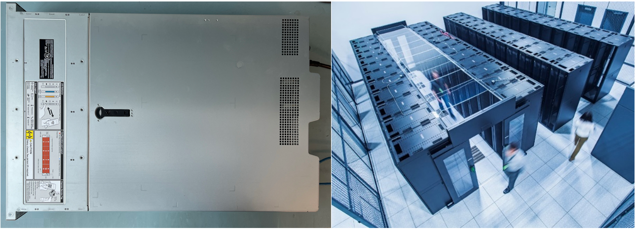
Figure 1. A Dell server in a benchtop operation environment (left), and a data center server room (right)
Racked server thermal needs
Dell applies thermal management design principles from the server level to rack and to the host room. Ensuring proper cooling levels (that is, neither over- nor under-cooling) and sealing off low air pressure from high air pressure zones helps deliver a balance of performance and efficiency. Appropriate rack level airflow provisioning balances thermal management with room-level energy efficiency.
With hot aisle temperatures in data centers typically ranging from 40-50°C, and increasing in the future, server design should minimize airflow leakage and ensure sufficient air supply to critical components. This requires preventing unintentional bypass, which occurs when air flows around instead of reaching target components. Sealing around air movers in a server is a common way to help in this regard. At the rack level, zero-U blanking prevents bypass around servers in the area between the mounting posts and rack sidewalls and are often preinstalled. Blanking panels prevent cold air from bypassing servers and going through unoccupied server spaces, thereby ensuring maximal airflow through the servers. Beyond the rack level, data centers use hot or cold aisle containment to prevent mixing of room level air.
Chassis vents
Adding vents can improve benchtop performance but may be detrimental in a rack setup. Vents often allow air to bypass components that, while needing airflow, tend also to be impediments to airflow. For example, storage devices are blocks of mass which air must squeeze through while also cooling the drives. Vents thus provide fresh air to downstream components. Conversely, they can allow air to exit towards the back of a server without all the airflow having to go around sufficiently cooled components. But when the same servers are installed into racks, the vents may allow hot air from the data center exhaust aisle to enter the server and result in degraded system performance, throttling, or even shutdown.
We will explore these effects at three chassis airflow vent locations: adjacent to front end storage, downstream of the storage, and at the rear of the chassis. Figure 2 shows the zones of commonly added vents.
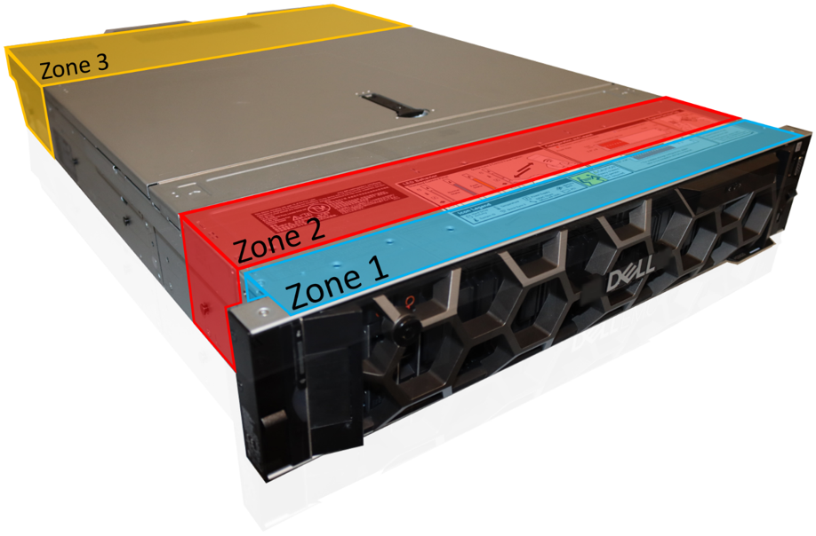
Figure 2. A Dell server chassis with labels indicating common venting locations
Effects of added chassis vents on benchtop performance
Adding vents in the labeled zones generally improves benchtop thermal performance. The mechanism by which this happens is increased server airflow that avoids narrow pathways. The same fans can then draw greater quantities of air at the same operational point. While benchtop results show overall higher airflow, the bypassed components must be monitored for sufficient airflow.
- Zone 1 increases system airflow by bypassing the dense front storage array, which is typically cooled with air through the front bezel.
- Zone 2 is usually on the side of the chassis downstream of the storage but upstream of fans. This inlet area allows for increased system airflow because the vents are not located directly adjacent to the dense storage arrays, which obstruct the vent flow. All components downstream of the vents would see significantly increased airflow at room temperatures during benchtop testing.
- Zone 3 allows for less obstructed outlet flow but operates on a similar principle to increase overall airflow. It vents air out rather than drawing air in due to its location near the chassis outlet.
Note that these zones cover the more common areas, and do not cover all potential areas for venting.
In-rack effects of chassis venting
Placing servers in a rack within a data center requires more nuanced and careful venting design considerations. Neighboring servers, rack level airflow, and data center design are just some of the variables. Zone 1 and Zone 3 vents can provide rack level benefits and may be seen in Dell server design. While Zone 1 vents can provide airflow from the adjacent cold aisle, other servers or 1U blanking panels will largely occlude the vents, because they are typically on the top or bottom of the servers. Zone 3 pushes air out rather than pulling air in, making the risk of hot aisle air recirculation low. Either of these zones can include additional chassis vents when bypassed components such as IO and drives have sufficient airflow
Zone 2 venting, often implemented at the side of a chassis, generally worsens server thermal performance in a data center environment. Server fans pull in significant amounts of hot aisle air into the low impedance volume between the server sides and rack wall. The additional airflow is recirculated hot aisle air, nearer to the hot aisle temperatures instead of cool air.
A computer simulation model of a Dell PowerEdge HS5620 server was modified to include side venting to demonstrate their rack-level effects, as shown in Figure 3. The impedance of the storage and compute modules were independently simulated as functions of velocity, allowing the server to be modeled as two simplified blocks with assigned impedance functions and thermal loads. Six 60x56 mm fans were placed at the front of the compute chassis, and side vents were added upstream of the fans. Twenty-one of the models were used to fully populate a 42U rack with cold aisle containment. Fan derating factors set to 0.65 achieved a ΔT of 20°C across the servers prior to side vent inclusion or placement in the rack level geometry.
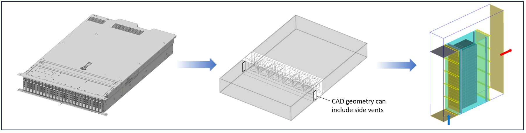
Figure 3. Isometric view of a Dell PowerEdge HS5620 server (left), simplified models with Zone 2 side vents added (middle), and 21 total servers installed into a rack (right)
Two computational fluid dynamics (CFD) simulations were performed to illustrate the impacts of side vents in data center deployments. An inlet condition with a 20°C inlet temperature and an open outlet condition were imposed on the fully populated rack model. The inlet boundary condition provided a balanced airflow of 1600 CFM. Because complete sealing was assumed, the simulation is an approximation rather than an exact replica.
Examination of the streamlines in Figure 4 shows two different behaviors. Side venting creates significant recirculation zones spanning from the side vent inlet to the back of the server. The flow field behavior also affects the temperature profiles, as the recirculation causes a temperature feedback loop and thus hotspots to form near the side walls. That is, adding side vents in a well-sealed rack will effectively use hot aisle air to augment airflow.
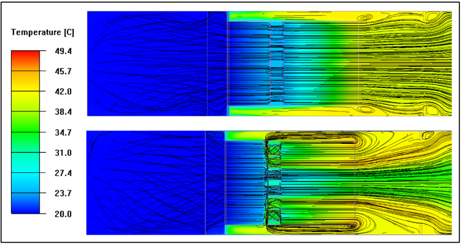
Figure 4. Top view streamlines with temperature contours at the middle server location for the case without side vents (top image) and case with side vents (bottom image)
Examining the net airflow values demonstrates another interesting effect – while the total airflow out of the back of the server increases, the increased airflow is nominally at hot aisle air temperatures, as shown in Figure 5. Nearly half of the total airflow (61 CFM, or cubic feet per minute, of the total 135 CFM) comes through the side vents with average air temperatures of 39°C, close to the average outlet temperatures of 41°C. Any benefits of increased airflow are largely negated because the recirculated hot aisle airflow puts components near the chassis side walls at greater risk, compared to components downstream of the middle fans.
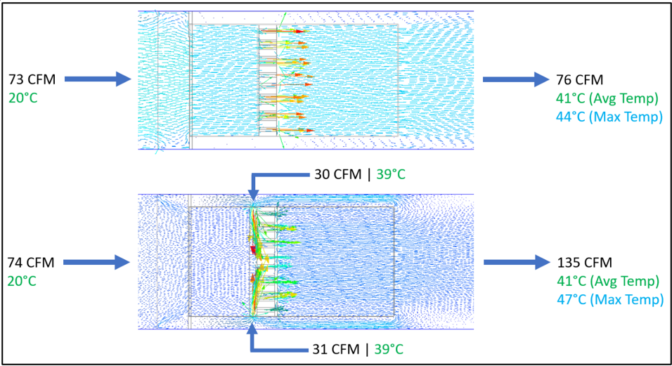
Figure 5. Top view of velocity vectors at the middle server location for the case without side vents (top image) and case with side vents (bottom image)
Conclusions
As server power requirements continue to climb, chassis thermal design and management with air cooling becomes increasingly vital. Rack and benchtop deployments are observed to have thermally different behaviors. In rack deployments within data centers, and particularly in energy conscious rooms, side venting can be detrimental. These negative impacts are not seen when only benchtop testing is run. Rack-level simulations with and without side vents were performed. The side vents drew in hot aisle air at 39°C, leading to recirculation and hot spots within the server. As we have seen, designs focused on benchtop performance may be detrimental to racked server objectives.