


Dell ObjectScale Data Path Overview Part II
Wed, 10 Jan 2024 16:14:05 -0000
|Read Time: 0 minutes
This blog is a continuation of the Dell ObjectScale Data Path Overview Part I. Here, I will cover data protection and dataflow. If you haven’t already, feel free to check out the Dell ObjectScale Data Path Overview Part I to get some basic knowledge about chunks, metadata, and the B+ tree.
Data protection methods
An object created within ObjectScale includes writing data and metadata. ObjectScale metadata includes journal chunks and btree chunks. Each is written to a different logical chunk that will contain ~128 MB of data from one or more objects. ObjectScale uses a combination of triple mirroring and erasure coding to protect the data.
- Triple mirroring ensures that three copies of data are written, protecting against two node failures.
- Erasure coding provides enhanced data protection from disk and node failures, using the Reed Solomon erasure coding scheme which breaks up chunks into data and coding fragments that are equally distributed across nodes.
- ObjectScale uses 12+4 erasure coding. That means a chunk is broken into 12 data segments and another 4 coding (parity) segments.
Depending on the size and type of data, data is written using one of the data protection methods shown in the following table.
Table 1. Data protection methods based on data type and size
Type of data | Data protection method used |
Journal chunks/ Btree chunks | Triple mirroring |
Object data <128 MB | Triple mirroring plus in-place erasure coding |
Object data >=128 MB | Inline erasure coding |
Note: In the ObjectScale appliance (XF960) with NVMe architecture, the object data will have inline erasure coding when >=44MB. In this blog, we will talk about 128MB chunk as default.
Triple mirroring
The triple-mirror write method applies to the ObjectScale journal and Btree chunks, of which ObjectScale creates three replica copies. Each replica copy is written to a single disk on different nodes. This method protects the chunk data against two-node or two-disk failures.
Triple mirroring plus in-place erasure coding
This write method is applicable to the data from any object that is less than 128 MB in size.
As an object is created, it is written as follows:
- One copy is written in fragments that are spread across different nodes and disks.
- A second replica copy of the chunk is written to a single disk on a node.
- A third replica copy of the chunk is written to a single disk on a different node.
- Other objects are written to the same chunk until it contains ~128 MB of data. The erasure coding scheme calculates coding (parity) fragments for the chunk and writes these fragments to different disks.
- The second and third replica copies are deleted from disk.
- After this sequence is complete, the chunk is protected by erasure coding.
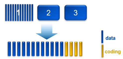
Figure 1. Process of triple mirroring plus in-place erasure coding
Inline erasure coding
This write method is applicable to the data from any object that is 128 MB or larger. Objects are broken up into 128 MB chunks. The Reed Solomon erasure coding scheme calculates coding (parity) fragments for each chunk. Each fragment is written to different disks across the nodes.
Any remaining portion of an object that is less than 128 MB is written using the triple mirroring plus in-place erasure coding scheme. As an example, if an object is 150 MB, 128 MB is written using inline erasure coding. The remaining 22 MB is written using triple mirroring plus in-place erasure coding.
Checksums
Checksums are done per write-unit, up to 2 MB. During write operations, the checksum is calculated in memory and then written to disk. On reads, data is read along with the checksum. The checksum is then calculated in memory from the data read and compared with the checksum stored in disk to determine data integrity. Additionally, the storage engine runs a consistency checker periodically in the background and does checksum verification over the entire dataset.
Data flow
ObjectScale was designed as a distributed architecture and includes a built-in load balancer (Metallb by default) that chooses the node in a cluster that will respond to a read or write request.
The following figure and steps provide a high-level overview of a write dataflow.
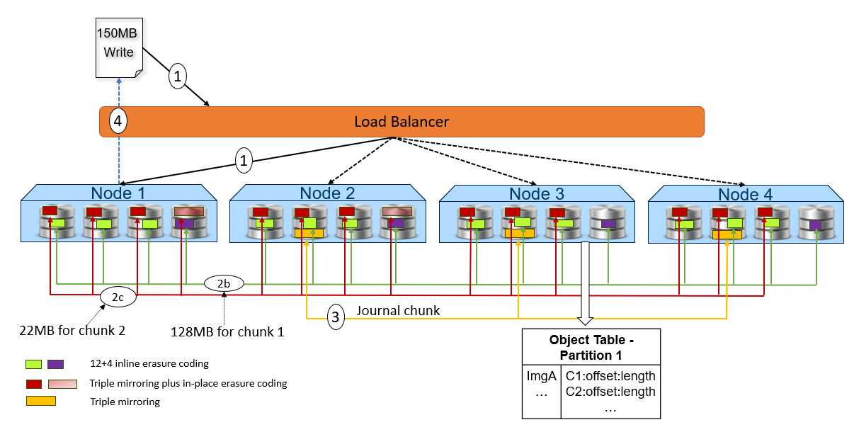
Figure 2. High-level overview of a write dataflow
- A write object request is received. In this example, Node 1 processes the request.
- Depending on the size of the object, the data is written to one or more chunks. Each chunk is protected using advanced data protection schemes such as triple mirroring plus in-place erasure coding and inline erasure coding. Before writing the data to disk, ObjectScale runs a checksum function and stores the result.
- In this example, the object size is 150MB and will be divided into 128MB as chunk 1 and 22MB as chunk 2.
- For the chunk 1 with 128MB size, it uses the inline erasure coding scheme (12+4).
- For the chunk 2 with 22MB size, it uses the triple mirroring plus in-place erasure coding scheme.
- After the object data is written successfully, the object metadata will be stored. In this example, Node 3 owns the partition of the object table in which this object belongs. As owner, Node 3 writes the object name and chunk ID to this partition of the object table’s journal logs. Journal logs are triple mirrored, so Node 3 sends replica copies to three different nodes in parallel—Node 2, Node 3, and Node 4 in this example.
- Acknowledgment is sent to the client.
- In a background process, the memory table is updated.
The following figure and steps provide a high-level overview of a read dataflow.
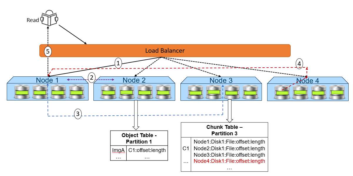
Figure 3. High-level overview of a read dataflow
- A read request is received for ImgA. In this example, Node 1 processes the request.
- Node 1 requests the chunk information from Node 2 (object table partition owner for ImgA).
- Knowing that ImgA is in C1 at a particular offset and length, Node 1 requests the chunk’s physical location from Node 3 (chunk table partition owner for C1).
- Now that Node 1 knows the physical location of ImgA, it requests that data from the node or nodes that contain the data fragment or fragments of that file. In this example, the location is Node 4 Disk 1. Then, Node 4 performs a byte offset read and returns the data to Node 1.
- Node 1 validates the checksum together with the data payload and returns the data to the requesting client.
Note: In step 4, for NVMe architecture like ObjectScale appliance, each node can directly read data from the other node. This architecture contrasts with a hard-drive architecture in which each node can only read its own data store and then transfer to the request node.
Resources
The following Dell Technologies documentation provides additional information related to this blog. Access to these documents depends on an individual’s login credentials. For access to a document, contact a Dell Technologies representative.
Author: Jarvis Zhu