
VMware logical design
VMware logical design
-
From a logical perspective, traffic flows into and out of the on-prem system using a load-balancer. MetalLB is the default load balancer that is bundled and is recommended to be used. The MetalLB creates dynamic connections between the compute nodes and the external network interfaces. Current best practice for PowerFlex system is to create three special-purpose networks used for management, internal, and external traffic:
- Anthos on-prem admin network
- Anthos on-prem internal network
- Anthos on-prem external network
Create a new compute cluster with at least one compute server and one resource pool in the production workload vCenter to host the workloads in the production vCenter. This cluster requires VMware Dynamic Resource Scheduling (DRS) and one resource pool.
The following figure describes the logical configuration between Anthos clusters running in on premises data centers on PowerFlex, Anthos clusters on VMware, and Anthos clusters on GCP:
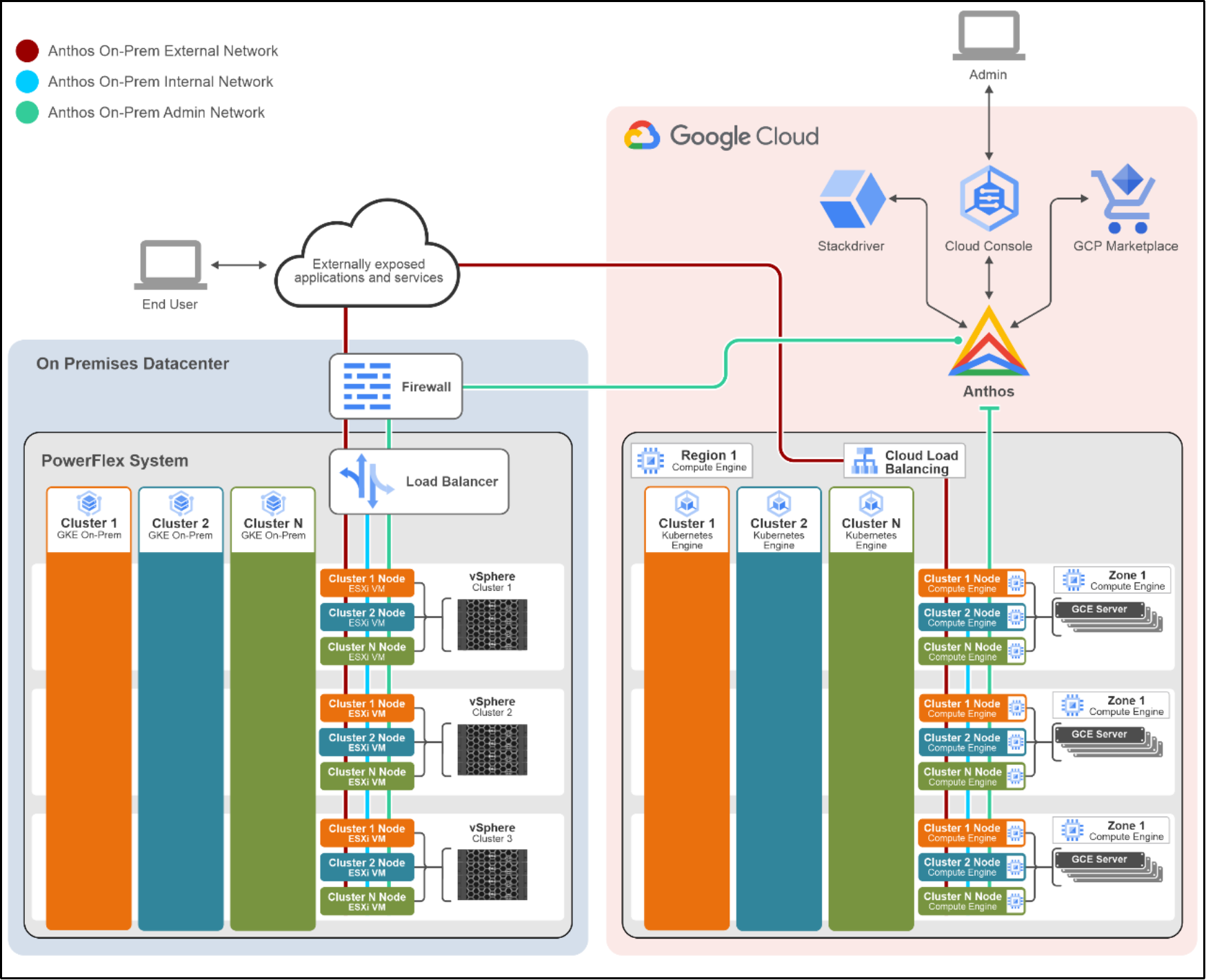 Figure 8: Logical design of an Anthos cluster deployed on the PowerFlex system
In this architecture, applications running on an Anthos on-prem cluster can be exposed internally or externally to the web without traffic passing through GCP.
Note: The Anthos on-prem Admin Network connection from the on-prem data center to Anthos is outbound only.
The production vCenter hosts multiple virtual machines in the new resource pool that consists of a virtual Anthos on-prem compute cluster. The application workloads are pods that run inside one of the Anthos on-prem compute GKE cluster virtual machines. When an application gets deployed into the Anthos on-prem compute GKE cluster, no additional vSphere virtual machines are created. If additional workload capacity is required, the Anthos on-prem compute cluster is expanded using the gkectl command-line utility or the Kubernetes Cluster API.
The summary of the correlation between vSphere VMs and Anthos on-prem cluster servers are as follows:
- Anthos on-prem cluster is a collection of vSphere VMs running a Kubernetes cluster as a collective instance.
- Anthos on-prem cluster’s performance profile (for example: RAM, CPU, storage, and so on) is the additive sum of all vSphere VMs running in the GKE on-prem cluster.
- Multiple Anthos on-prem clusters can exist in a single vCenter deployment.