
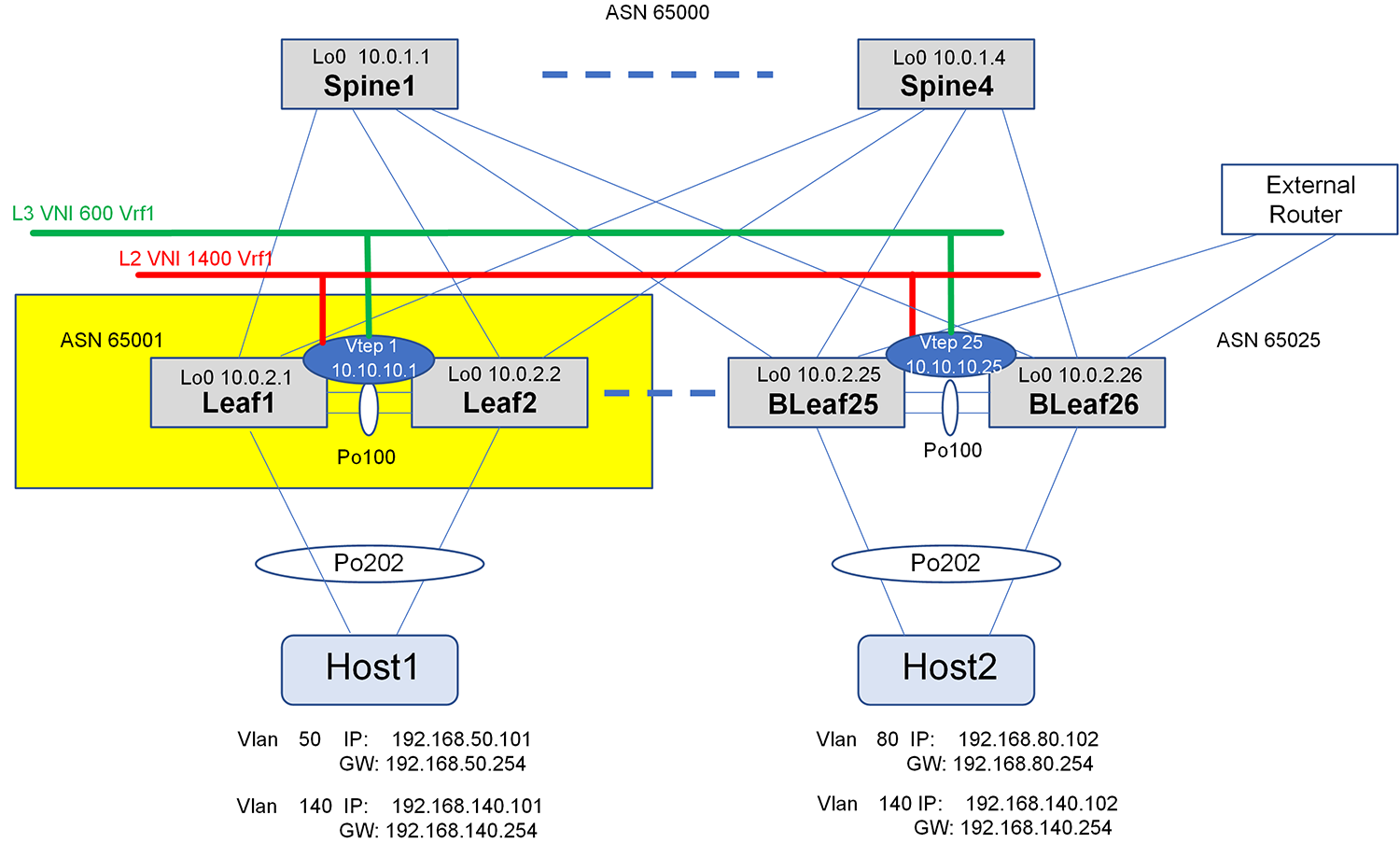
The following diagram highlights the leaf swiches configured in this section. Leaf1 and Leaf2 are configured as a MCLAG pair.
- Enter Management Framework CLI (MF-CLI) and then configuration mode.
- Change the interface naming mode to Standard and add a hostname.
- Exit back to Linux shell to activate the changes.
Leaf1 Leaf2 sonic-cli configure terminal interface-naming standard hostname Leaf1 end exitsonic-cli configure terminal interface-naming standard hostname Leaf2 end exit - Re-enter the MF-CLI and configuration mode
- Assign a loopback interface with a unique router ID on each leaf.
- Then enable IPv6 on spine uplinks to support unnumbered BGP point-to-point links and enable the interfaces.
Leaf1 Leaf2 sonic-cli configure terminal interface loopback 0 description router-id ip address 10.0.2.1/32 exit interface Eth 1/53 description Spine1 ipv6 enable no shutdown interface Eth 1/56 description Spine4 ipv6 enable no shutdown exitsonic-cli configure terminal interface loopback 0 description router-id ip address 10.0.2.2/32 exit interface Eth 1/53 description Spine1 ipv6 enable no shutdown interface Eth 1/56 description Spine4 ipv6 enable no shutdown exit - Assign a VRF for each tenant. This POC only has one tenant, but will support multiple tenants with additional VRFs.
- Configure VLANs 50 and 140 for the hosts, bind to the tenant's VRF and assign the same anycast-address to each host VLAN.
- Assign a dedicated VLAN (Vlan60) for a L3 VNI and bind to the tenant's VRF.
Note: The VLAN assigned to the L3 VNI does not need an IP address.
Leaf1 Leaf2 ip vrf Vrf-tenant1 interface Vlan 50 ip vrf forwarding Vrf-tenant1 ip anycast-address 192.168.50.254/24 neigh-suppress exit interface Vlan 140 ip vrf forwarding Vrf-tenant1 ip anycast-address 192.168.140.254/24 neigh-suppress exit interface Vlan 60 ip vrf forwarding Vrf-tenant1 exitip vrf Vrf-tenant1 interface Vlan 50 ip vrf forwarding Vrf-tenant1 ip anycast-address 192.168.50.254/24 neigh-suppress exit interface Vlan 140 ip vrf forwarding Vrf-tenant1 ip anycast-address 192.168.140.254/24 neigh-suppress exit interface Vlan 60 ip vrf forwarding Vrf-tenant1 exit - Configure the MCLAG peer-link and port channel members.
- Configure all VLANs on the MCLAG's peer-link port channel.
Note: The MCLAG peer-link must include the L3 VNI's VLAN.
Leaf1 Leaf2 interface PortChannel 100 description MCLAG-Peer-Link switchport trunk allowed vlan add 50,60,140 exit interface Eth 1/49 description MCLAG-Peer-Link channel-group 100 no shutdown exit interface Eth 1/51 description MCLAG-Peer-Link channel-group 100 no shutdown exitinterface PortChannel 100 description MCLAG-Peer-Link switchport trunk allowed vlan add 50,60,140 exit interface Eth 1/49 description MCLAG-Peer-Link channel-group 100 no shutdown exit interface Eth 1/51 description MCLAG-Peer-Link channel-group 100 no shutdown exitCAUTION: When copying and pasting the content from the table above, ensure that the underlined monospace text remains on one line. Failure to keep the underlined content on one line results in a line error on the switch. - Configure the MCLAG domain.
- The loopback IP address used for the router-id is also used as the MCLAG source and peer IP address.
- Assign the host's port channel interfaces and assign to the MCLAG domain.
Note: By default, port channels are LACP. Use the interface PortChannel <num> mode on command for static LAGs. If changing LAG modes, you must completely remove and reassign the port channel.
Note: The spine switches are used for the MCLAG peer keep-alive link communication
Leaf1 Leaf2 mclag domain 1 source-ip 10.0.2.1 peer-ip 10.0.2.2 peer-link PortChannel 100 delay-restore 90 exit interface PortChannel 202 description Host1_PortChannel switchport trunk allowed vlan add 50,140 mclag 1 exit interface Eth 1/3 description Host1_PortChannel channel-group 202 no shutdown exitmclag domain 1 source-ip 10.0.2.2 peer-ip 10.0.2.1 peer-link PortChannel 100 delay-restore 90 exit interface PortChannel 202 description Host1_PortChannel switchport trunk allowed vlan add 50,140 mclag 1 exit interface Eth 1/3 description Host1_PortChannel channel-group 202 no shutdown exit - Enable static anycast-address and assign a unique MAC to be used across all leaf switches.
- Create a loopback interface for the VTEP IP address. This address must be the same for each MCLAG peer.
- Create a VXLAN interface and assign the same VTEP source IP address to each peer.
- Assign a unique primary-ip to optimize routing for orphan ports and active-standby hosts. The router-id can be used for this purpose.
- Map the L2 VNI to the host VLANs that are stretched across the fabric.
- Create a L3 VNI by mapping the dedicated VLAN (Vlan60) to the non-default VRF.
Note: The Network Virtualization Overlay (NVO) is automatically assigned to the VXLAN interface.
Leaf1 Leaf2 ip anycast-address enable ip anycast-mac-address 00:00:00:00:01:02 interface Loopback 1 description LogicalVTEP ip address 10.10.10.1/32 exit interface vxlan vtep1 source-ip 10.10.10.1 primary-ip 10.0.2.1 map vni 1400 vlan 140 map vni 600 vlan 60 map vni 600 vrf Vrf-tenant1 exitip anycast-address enable ip anycast-mac-address 00:00:00:00:01:02 interface Loopback 1 description LogicalVTEP ip address 10.10.10.1/32 exit interface vxlan vtep1 source-ip 10.10.10.1 primary-ip 10.0.2.2 map vni 1400 vlan 140 map vni 600 vlan 60 map vni 600 vrf Vrf-tenant1 exit - Configure the BGP router with ECMP enabled.
- Configure the underlay's address-family and redistribute the connected networks.
- Add VNI advertisements to the EVPN address family and assign the MCLAG peer's primary-ip.
Leaf1 Leaf2 router bgp 65001 router-id 10.0.2.1 bestpath as-path multipath-relax address-family ipv4 unicast redistribute connected maximum-paths 2 exit address-family l2vpn evpn advertise-all-vni advertise-pip peer-ip 10.0.2.2 exitrouter bgp 65001 router-id 10.0.2.2 bestpath as-path multipath-relax address-family ipv4 unicast redistribute connected maximum-paths 2 exit address-family l2vpn evpn advertise-all-vni advertise-pip peer-ip 10.0.2.1 exit - Configure the BGP spine peer-group.
- Set timers and enable unnumbered BGP and BFD on the peer-group.
- Activate both IPv4 unicast and EVPN address families for the spine peer group.
- Set allowas-in to support MCLAG peer’s ASN to be received.
Leaf1 Leaf2 peer-group SPINE advertisement-interval 5 timers 3 9 remote-as external capability extended-nexthop bfd address-family ipv4 unicast activate allowas-in 1 exit address-family l2vpn evpn activate exit exitpeer-group SPINE advertisement-interval 5 timers 3 9 remote-as external capability extended-nexthop bfd address-family ipv4 unicast activate allowas-in 1 exit address-family l2vpn evpn activate exit exit - Assign the spine neighbor interfaces to the peer-group.
- Create the BGP router for each tenant’s VRF.
- Save the configuration.
Leaf1 Leaf2 neighbor interface Eth 1/53 peer-group SPINE exit neighbor interface Eth 1/56 peer-group SPINE exit exit router bgp 65001 vrf Vrf-tenant1 address-family ipv4 unicast redistribute connected exit address-family l2vpn evpn advertise ipv4 unicast exit exit end write memoryneighbor interface Eth 1/53 peer-group SPINE exit neighbor interface Eth 1/56 peer-group SPINE exit exit router bgp 65001 vrf Vrf-tenant1 address-family ipv4 unicast redistribute connected exit address-family l2vpn evpn advertise ipv4 unicast exit exit end write memory