
Storage design
Storage design
-
PowerStore T design features
This Ready Stack design consists of two PowerStore T appliances, each with two nodes in an all-NVMe base enclosure, in a two-appliance (four-node) cluster. The PowerStore unified storage appliances, which include dual-socket Intel Skylake architecture and the PowerStoreOS, support:
- SAN (FC/iSCSI)
- NAS (NFS/SMB/FTP/SFTP)
- vSphere Virtual Volumes (iSCSI)
The active/active architecture provides:
- All-node access to the same storage
- Active/optimized or active/unoptimized front-end connectivity
This Ready Stack design includes a connection to a 16 Gb FC storage network. The PowerStore T is designed for all-flash storage. With all-inclusive software, PowerStore T systems deliver consistent performance with low response times and are ideal for mixed virtual-workload requirements. Two Dell EMC Connectrix DS-6620B switches make up the FC fabrics.
The following table shows a comparison of the PowerStore storage arrays that this Ready Stack solution supports:
Table 3. PowerStore T storage arrays
PowerStore 1000T
PowerStore 3000T
PowerStore 5000T
PowerStore 7000T
PowerStore 9000T
CPU per appliance
4 x 8C @ 1.8 GHz Skylake
4 x 12C @ 2.1 GHz Skylake
4 x 16C @ 2.1 GHz Skylake
4 x 20C @ 2.4 GHz Skylake
4 x 28C @ 2.1 GHz Skylake
Memory per appliance
384 GB
768 GB
1,152 GB
1,536 GB
2,560 GB
NVRAM drives per appliance
2
4
Maximum storage drives per appliance
98
96
Supported drives
NVMe SCM, NVMe Flash, SAS SSD
Embedded ports
4 x 25/10/1 GbE Optical or 4 x 10/1 GbE BaseT
Support I/O modules (two slots per node)
4 x 32/16/8 Gb FC, 4 x 25/10/1 GbE Optical, 4 x 10/1 GbE BaseT
Supported expansion shelves
2.5-in., 25-drive SAS SSD
For more information, see the Dell EMC PowerStore Storage Family Spec Sheet.
Base enclosure
Between the front and back of the enclosure, a midplane distributes power and signals to all the enclosure components.
Front view
On the front of the base enclosure, drives connect to the midplane. On the back of the base enclosure, the nodes and power supply modules connect to the midplane. The I/O modules connect directly to the node. Each node contains an internal battery backup module, redundant fan modules, DDR4 memory, and two Intel Skylake processors.
The following figure shows the front of the base enclosure:
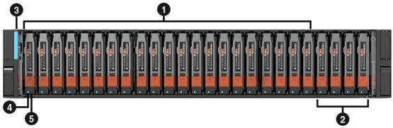
Location
Description

SSD or SCM NVMe drives

NVRAM NVMe drives
Note: With systems that use two NVRAM NVMe drives, the first two of these slots can be populated with SSD or SCM NVMe drives.

Base enclosure power-on LED

Drive ready/activity LED

Drive fault LED
Figure 11. Base enclosure front view
Back view
On the back of the base enclosure are two nodes: node A and node B. Each node contains the following hardware components:
- One embedded module
- Two optional I/O modules
- One power supply module
The following figure shows the back of the base enclosure:
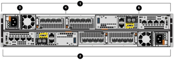
Location
Description
Node B
Node A
Power supply module
I/O module, slots 0 and 1
Embedded module
Figure 12. Base enclosure back view
Embedded modules
Each node contains one embedded module that can hold one 4-port card for front-end connectivity and internal communication between nodes and appliances.
The first two ports of the 4-port card on the embedded module connect to a 10 GbE/25 GbE switch.
The embedded module contains the following components:
- One 4-port card
- One nonmaskable interrupt (NMI) button
- Two mini-SAS HD back-end ports
- Two RJ45 LAN connectors
- System management port
- Service port
- One USB port
- One mini-serial port (unused)
- One DB9 serial port (unused)
4-port cards
The 4-port card is an optional component within the embedded module. The supported 4‑port cards are:
- 25 GbE SFP-based embedded module
- 10GBASE-T embedded module, which serves Ethernet (iSCSI) traffic and supports 1 GbE and 10 GbE
I/O modules
PowerStore-T systems support the following base enclosure I/O modules:
- 4-port 25 GbE SFP-based I/O module—Serves Ethernet network traffic and iSCSI (block) traffic to platform hosts. The I/O module uses an optical 10 GbE or 25 GbE-capable SFP+ connection to a host or switch port.
- 4-port BaseT I/O module—Operates at speeds of 1 Gbps and 10 Gbps, and supports both Ethernet network traffic and iSCSI (block) traffic on the same node. Ports can be configured as both IP and iSCSI simultaneously. The I/O module comes with four 10 Gbps RJ45 ports with a power/fault LED, activity LED, and link LED for each port.
- 4-port 32 Gb FC I/O module—Serves FC-SAN (block) traffic to platform hosts. The I/O module is available with either 16 Gb FC SFP modules or with 32 Gb FC SFP modules. Each port has an optical 16Gb/32Gb-capable SFP connection to a host or switch port.
Internal node components
Included within each node are the following components:
- DIMMs—Twenty-four, 288-pin DIMM sockets support up to 24 DDR4 DIMMs, capable of up to 1,280 GB of memory.
- Internal M.2 boot modules—Each node has two internal M.2 boot modules on an M.2 boot module adapter between DIMM slots 11 and 12. One internal M.2 boot module is used for general system operations, while the other internal M.2 boot module is used for recovery.
- Internal battery backup module—The node includes a lithium-ion internal battery that powers the associated NVRAM cache drives (BMC and NVRAM drives) during a power event.
- Fan module—Seven redundant fan modules connect to the motherboard within the node to provide continuous airflow through the front drives and through the back of the node to keep the components at optimal operating temperatures.
Expansion enclosure
The drive expansion enclosure is 2U (3.5 inches high) and includes slots for twenty-five 2.5-inch drives. It uses a 12 Gbps SAS interface for communication between the nodes and the expansion enclosure.
Front view
The front of the expansion enclosure includes the following components:
- Drives in 2.5-inch carriers (hot-swappable)
- Status LEDs
The following figure shows the front of the expansion enclosure:
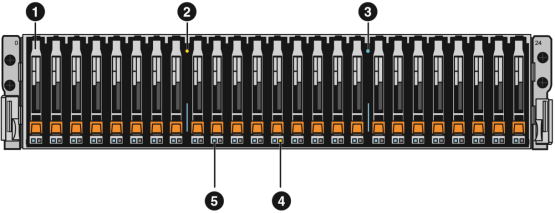
Location
Description
2.5-in. 12 Gbps SAS drives
Expansion enclosure fault LED (amber)
Expansion enclosure power status LED (blue)
Drive fault LED (amber)
Drive status/activity (blue)
Figure 13. 2U, 25-drive expansion enclosure front view
Back view
The following components are on the back of a 2U, 25-drive expansion enclosure, as shown in Error! Reference source not found.:
- Two 12 Gbps SAS link control cards (LCC)—A (
 ) and B (
 )
) - Two power supply/cooling modules—A (
 ) and B (
 )
)
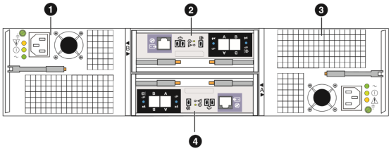
Figure 14. 2U, 25-drive expansion enclosure back view
Components of base and expansion enclosure boxes
The PowerStore T base enclosure box contains the following components:
- 2U base enclosure (1)
- Rails (2)
- Power cables (6)
- Mini-SAS HD cables (2)
- Bezel, with key (1)
- Electrostatic discharge clip (1)
The optional PowerStore T expansion enclosure box contains the following components:
- 25-drive expansion enclosure (1)
- Rails (2)
- Mini-SAS HD cables (2)
- Power cables (2)
- Bezel, with key (1)
- Cable label sheet (3)
PowerStore T storage configuration
PowerStore T provides two storage configuration options during the initial system configuration:
- Unified—Default storage configuration (factory state) for:
- SAN, NAS, and vSphere Virtual Volumes
- Block and file components
- Block Optimized—Alternate storage configuration for:
- SAN and vSphere Virtual Volumes
- Block components only
Changing the storage configuration requires a factory reset.
PowerStore T networking
The PowerStore network is a subset of IP addresses in a single subnet within an L2 broadcast domain. This network consists of an IP address range, network prefix, gateway, and a VLAN.
PowerStore T requires the following distinct networks:
- Initial discovery network
- Management network
- Storage network
- Intra-cluster management network
- Intra-cluster data network
- Appliance node interconnect network
Physical networks
The PowerStore T networks are grouped into the following physical networks:
- Management network
- 1 x OOB management switch
- 2 x OOB management (supported for HA)
- Onboard 1 GbE ports
- Data network
- 2 x ToR Ethernet switches
- Bonded 4-port card (ports 0 and 1)
- Layer 2 interconnect
- Backplane interconnect
- 2 x 10 GbE
Figure 15 shows the minimum required cabling for these networks.
System bond
PowerStore T models contain a system bond by default. This bond is essential to the networking configuration and cannot be removed. The system bond provides high availability to cluster data and metadata traffic. In this bond, ports 0 and 1 of a 4-port card are automatically bonded together in LACP mode.
Switches
To provide high availability, this design requires the following dual Ethernet switches, each running OS10 Enterprise Edition (OS10EE):
- S4148T-ON
- 48 fixed 10GBASE-T ports
- 8 fixed 50 GbE QSFP28 ports
- 4 fixed 100 GbE QSFP28 ports
- S5248F-ON
- 48 fixed 25 GbE SFP28 ports
- 4 fixed 100 GbE QSFP28 ports
- 2 fixed 200 GbE QSFP28-DD ports
Connecting the base enclosure to the switches
PowerStore T deployments require OOB management switch connectivity with at least one OOB management switch. A second OOB management switch is optional and can be used for high availability. An OOB management switch can be configured with or without a management VLAN.
Switch ports must support untagged native VLAN traffic for system discovery.
This design includes a single OOB management switch. Two ToR switches provide high availability. Layer 2 connectivity is configured between ToR switches.
The following figure shows the network cabling:
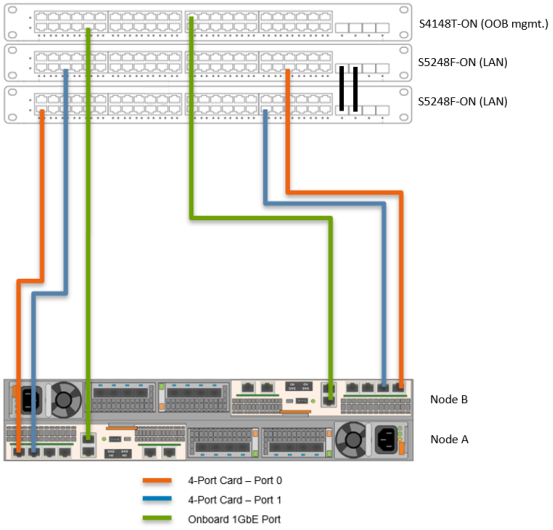
Figure 15. Network cabling
Connect the base enclosure to the switches as follows:
- Connect the network cables on node A:
- Connect port 0 of the embedded module to switch 1.
- Connect port 1 of the embedded module to switch 2.
- Connect the network cables on node B:
- Connect port 0 of the embedded module to switch 2.
- Connect port 1 of the embedded module to switch 1.
- Connect the Ethernet switches by connecting two 100 GbE ports of the bottom switch to two 100 GbE ports of the top switch.
- Connect the management interface on both nodes.
Connecting the Fibre Channel SAN
The following figure shows the FC connections for a typical setup of redundant A/B SANs.
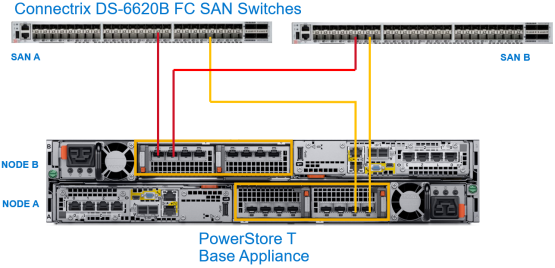
Figure 16. FC SAN connections
Connect the 32 Gb FC ports in the optional FC I/O modules to the Connectrix DS-6620B SAN switches, as follows:
- Connect one FC port in Node A to one switch port in SAN A.
- Connect another FC port in Node A to one switch port in SAN B.
- Repeat the preceding steps to connect the FC ports in Node B to the switch ports in SAN A and SAN B.
Connecting the expansion enclosure to the base enclosure
When connecting the expansion enclosure to the base enclosure, connect both embedded modules on the base enclosure to the link control card (LCC) on the expansion enclosure, as shown in Figure 17:
- Connect node A, SAS port B to LCC A, port A on the expansion enclosure (1).
- Connect node B, SAS port B to LCC B, port A on the expansion enclosure (2).
- Connect node B, SAS port A to LCC A, port B on the expansion enclosure (3).
- Connect node A, SAS port A to LCC B, port B on the expansion enclosure (4).
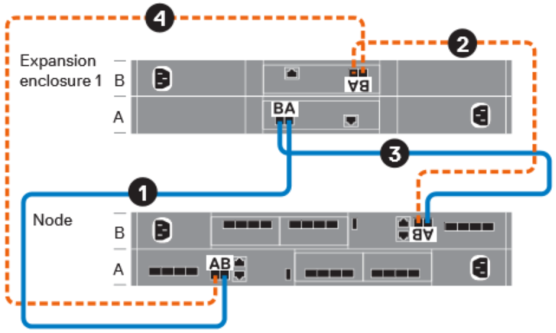
Figure 17. Connecting the expansion enclosure to the base enclosure