
Network design
Network design
-
Dell EMC PowerSwitch S5248F-ON switches
The network architecture of this Ready Stack design employs a Virtual Link Trunking (VLT) connection between the two ToR switches. In a VLT environment, all paths are active, adding immediate value and throughput while still protecting against hardware failures. The inherent redundancy of a non-VLT environment requires standby equipment, which drives up infrastructure costs and increases risks.
VLT technology allows a server or bridge to uplink a physical trunk to more than one PowerSwitch S5248F-ON switch by treating the uplink as one logical trunk. A VLT-connected pair of switches acts as a single switch to a connecting bridge or server. Both links from the bridge network can actively receive and forward traffic. VLT provides a replacement for Spanning Tree Protocol (STP)-based networks by providing both redundancy and full bandwidth utilization through multiple active paths.
VLT technology provides:
- Dual control plane for highly available resilient network services
- Full utilization of the active link aggregation group (LAG) interfaces
- Active/active design for seamless operations during maintenance events
PowerSwitch S5248F-ON switches each provide six 100 GbE uplink ports. The following figure shows the VLT interconnect (VLTi) configuration in this architecture:
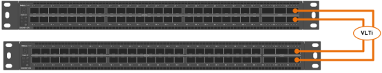
Figure 7. PowerSwitch S5248F-ON VLTi configuration
The configuration uses two 100 GbE ports from each ToR switch to provide a 200 Gb data path between the switches. The remaining four 100 GbE ports allow for high-speed connectivity to spine switches or directly to the data center core network infrastructure. They can also be used to extend connectivity to other racks.
Dell EMC PowerSwitch Z9264F-ON switches
You can scale out the Ready Stack by adding multiple compute nodes (pods) in the data center. You can use the Dell EMC PowerSwitch Z9264F-ON switch to create a simple yet scalable network, as shown in the following figure:
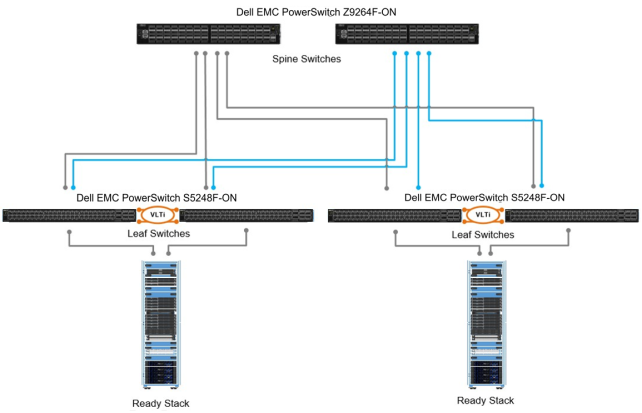
Figure 8. Multiple compute pods scaled out using leaf-spine architecture
The Z9264F-ON switches serve as the spine switches in the leaf-spine architecture. The Z9264F-ON is a multiline rate switch that supports 10/25/40/50/100 GbE connectivity and can aggregate multiple racks with little or no oversubscription.
When connecting multiple racks, by using the 40/100 GbE uplinks from the rack you can build a large fabric that supports multiterabit clusters. The density of the Z9264F-ON enables flattening the network tiers and creating an equal-cost fabric from any point to any other point in the network.
For large domain Layer 2 requirements, you can use extended multidomain VLT on the Z9264F-ON, as shown in the following figure. The VLT pair can scale in terms of hundreds of servers inside multiple racks. Each rack has six 100 GbE links to the core network (two are used for VLT), providing enough bandwidth for all the traffic between each rack.
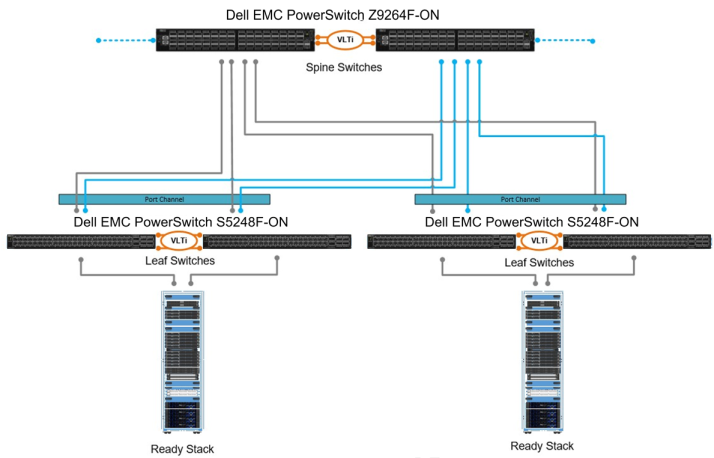
Figure 9. Multiple compute pods scaled out using multidomain VLT
Network configuration for PowerEdge rack servers
The compute cluster consists of Dell EMC PowerEdge rack servers. The compute and management rack servers have two 10/25 GbE connections to S5248F-ON switches through one Mellanox ConnectX-4 LX dual-port 10/25 GbE network card.
Network configuration for vSphere Distributed Switch LAN traffic
You can achieve bandwidth prioritization for different traffic classes such as host management, vSphere vMotion, and the VM network using vSphere Distributed Switch (VDS). VDS, which can be configured, managed, and monitored from within vCenter, provides:
- Simplified VM network configuration
- Enhanced network monitoring and troubleshooting capabilities
- Support for network bandwidth partitioning when Network Partitioning (NPAR) is not available
The following figure shows the VDS configuration for the management and compute servers:
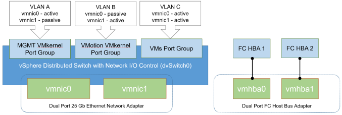
Figure 10. VDS configuration