
Network Edge Architecture Overview
Network Edge Architecture Overview
-
Modern data center networks are designed to serve the connectivity needs of applications that are considerably different from traditional client/server applications. In the client/server era, the traffic volume was small. With the dominance of highly clustered, distributed applications, there is a massive increase in east-west traffic in the data center (server-server, server-storage, and so on). A customer virtual machine (VM) might reside across multiple nodes but needs to communicate smoothly. Customers now want to quickly set up a private network for cloud. Thus, the need for rapid deployment becomes obvious. In addition, customers want to scale out the network in such a way that if one link or multiple links fail, there is no significant failure. An alternative to the traditional access-aggregation-core network model is becoming more widely used. The following figure shows this architecture, which is known as a Clos or leaf-spine network and is designed to minimize the number of hops between hosts:
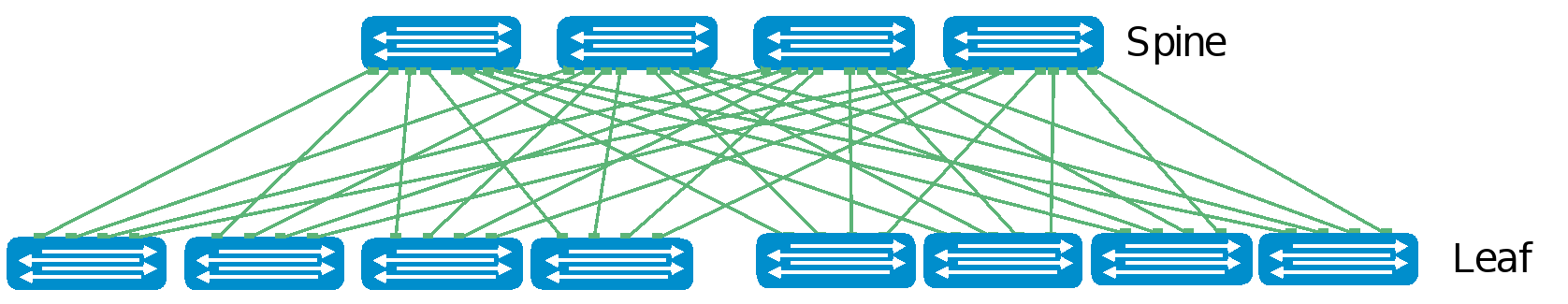
Enterprise SONiC CLOS Reference Architecture
Figure 6. Enterprise SONiC CLOS Reference Architecture
In a leaf-spine architecture, the access layer is referred to as the leaf layer. Servers and storage devices connect to leaf switches at this layer where all switches are typically the same model. At the next level, the aggregation and core layers are condensed into a single spine layer. Every leaf switch connects to every spine switch to ensure that all leaf switches are no more than one hop away from each other for predictable performance. This minimizes latency and the likelihood of bottlenecks in the network. Each leaf-spine network is called a POD or a cluster. Some networks may have an additional third tier of spine connecting all the clusters called the interpod spine layer or superspine.
A leaf-spine architecture is highly scalable. As administrators add racks to the data center, a pair of leaf switches is added to each new rack. Spine switches can be added as bandwidth requirements increase. With more than two spines, the loss of a single link/node is not catastrophic as the rest of the network continues to use the available bandwidth.
The total number of leaf-spine connections is equal to the number of leaf switches multiplied by the number of spine switches. The bandwidth of the fabric may be increased by adding connections between leafs and spines if the spine layer has capacity for the additional connections.
Layer2, Layer3, and overlay technologies can be deployed on these leaf/spine fabrics to achieve the data center functionality. Based on the network size, scale and application needs, either of these technologies can be used.
Typical edge deployment uses all three types based on the scale and usage. In this document, overlay technology is deployed as it is the most versatile control plane and can also provide multisite data center interconnect technology that is used to interconnect the multiple retail edge networks to the core data center networks. Because this type of multisite DCI is common in retail edge use cases, it helps to understand how it is deployed at the edge.
Multi-Chassis Link Aggregation (MCLAG)
Connecting the server’s Network Interface Card (NIC) to a single leaf or pair of leafs is possible. Providing path diversity from the servers to the network offers redundancy for equipment failures, but also reduces downtime during upgrades. Path diversity may have the added benefit of increased throughput when active/active mode is used. Connecting a rack of servers to a single leaf might simplify and reduce networking costs, but the failure or upgrade of a single leaf will cause a significant capacity loss.
A ToR consisting of a pair of leaf switches can be configured with (MCLAG to support dual homing. MCLAG supports active/active Layer 2 connectivity with a Link Aggregation Group (LAG) between a server and a leaf pair. Leaf pairs with MCLAG appear to the NIC as a single switch. Smaller data centers might prefer dual homing if losing a rack of servers is not tolerable. However, deploying an MCLAG adds additional complexity to the configuration and operation.
Network virtualization
VXLAN protocol
VXLAN is designed to scale a Layer 2 network over the IP network commonly deployed in data centers and is described in RFC 7348. It uses UDP/IP as the primary encapsulation technology to allow existing network equipment to load balance packets over multiple paths. In VXLAN, the tunnel edges are called VXLAN tunnel endpoints (VTEPs).
VXLAN is a tunneling protocol that provides new ways to scale the tenants while decoupling the underlay network from a tenant overlay network using a Layer 3 IP-based underlay coupled with a VXLAN-EVPN overlay. Customers can now deploy much larger networks with endpoints (servers or virtual machines) to be placed anywhere in the network and which remain connected to the same logical L2 network. EVPN is the control plane for VXLAN that resolves scalability concerns and reduces flooding in the network. It uses multiprotocol BGP (MP-BGP) to exchange information between VXLAN tunnel endpoints (VTEPs). EVPN was introduced in RFC 7432, whereas VXLAN-based EVPN was outlined in RFC 8365.
VXLAN-based EVPN is the next-generation VPN. It is designed to replace previous generation VPNs like Virtual Private LAN Service (VPLS). Some of the major benefits include:
- Scalability: The main benefit of a VXLAN over 802.1Q is scalability. The 12-bit VLAN Identifier (VID) allows only 4,094 VLANs. However, VXLAN supports a 24-bit VNI construct that enables 16 million virtual networks.
- Provisioning: The second benefit of overlay networks is that they allow rapid provisioning of virtual networks. As you configure only the concerned edges instead of the entire network, the core network is unaware of these virtual networks, and does not need to be configured.
- Cost-effective: Another major advantage is that it allows for the reuse of the existing infrastructure so only the edges participate in supporting the semantics of virtual networks. So, if virtual network software needs to be updated, only the edges need to be updated.
VXLAN encapsulation adds approximately 50 bytes of overhead to each Ethernet frame. As a result, all switches in the underlay (physical) network must be configured to support an MTU of at least 1,600 bytes on all participating interfaces. VTEPs handle VXLAN encapsulation and de-encapsulation. In this implementation, the leaf switches are the VTEPs.
VXLAN BGP EVPN
Ethernet VPN-Virtual Extensible LAN (EVPN-VXLAN) provides large enterprises with a common framework for managing their edge and core data center networks. An EVPN-VXLAN architecture supports efficient Layer 2 and Layer 3 network connectivity with scale, simplicity, and agility, while also reducing Operational Expense costs.
EVPN uses BGP to exchange endpoint MAC and IP address information between VTEPs. When a host sends a packet to an endpoint, the switch looks up the routing table for a match. If it finds a match that exists behind another VTEP, the packet is encapsulated with VXLAN and UDP headers and encapsulated again with outer IP and Ethernet headers for transport over the leaf-spine network. When the packet arrives at the destination VTEP, the outer Ethernet, IP, UDP, and VXLAN headers are removed, and the switch sends the original packet to the endpoint.
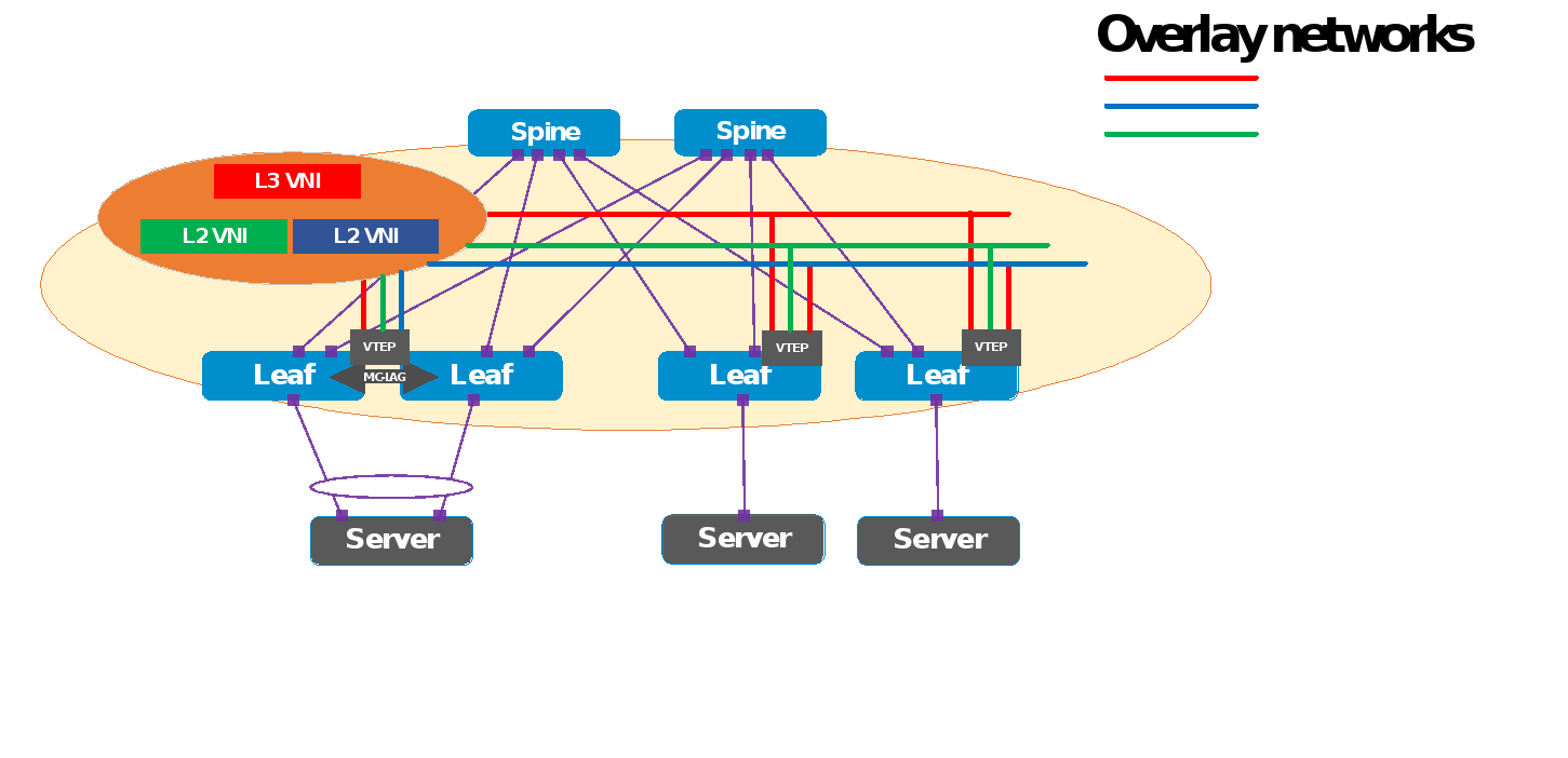
Figure 7. VXLAN BGP EVPN deploy topology
Key VxLAN features are:
- Support for multi-tenancy
- Layer 2 and Layer 3 integrated routing and bridging (IRB)
- Multi-homing
- Minimization of ARP propagation
- MAC mobility (simplified VM migration)
The primary use cases for EVPN are:
- Greatly expanding the potential number of Layer 2 domains
- Service provider multi-tenant hosting
- Data center interconnect (DCI)
Integrated Routing and Bridging (IRB)
Every VTEP is the first-hop router for its locally attached network, allowing the routing operation to occur as close to the end host as possible. There are two forwarding models for the IRB functionality:
- Symmetric IRB, in which both the ingress and egress VTEPs route the packet to its final destination. The ingress VTEP routes the packet to the final --destination with the egress VTEP as the next hop. After decapsulating the packet, the egress VTEP performs a routing lookup to route it to the destination using the IP header. The VNI used to carry the packet between the ingress and egress VTEPs is an L3 or VRF VNI. This L3 VNI is different from the L2 VNI of the source or destination network.
- Asymmetric IRB, in which the ingress and egress VTEPs behave differently. The ingress VTEP performs a routing lookup to decide to which egress VTEP the packet should be destined. The egress VTEP decapsulates the packet and then bridges the packet to its final destination using the MAC header. For the asymmetric model to operate, the ingress VTEP needs the information for all the tenant’s hosts to route and bridge the packet. The ingress VTEP must remember the destination network for routing functionality.
The following table compares shows the comparison between the IRBs.
Table 1. Symmetric compared to asymmetric comparison
Symmetric IRB
Asymmetric IRB
Ingress VTEP needs only the MAC destination address of the corresponding egress VTEP router.
Ingress VTEP needs the MAC destination address of the end station to which the packet is destined.
Egress VTEP routes the packet after decapsulation
Egress VTEP only bridges after decapsulation
L3 VNI mapped to VRFs and many L2 VNIs mapped to a given VRF. Cannot be deployed in default VRF.
No L3 VNI concept, however VRFs can be created for each tenant. Can be in VRF as well.
Centralized routing is not possible with Symmetric IRB
Centralized routing is possible with Asymmetric IRB
PoE/PoE+
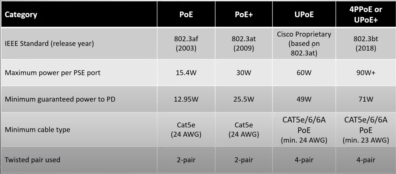
SONiC Edge Bundle provides the Power Over Ethernet (PoE), feature. PoE technology allows IP telephones, wireless LAN access points, web cameras, and many other appliances to receive power and data over the existing copper LAN cabling, without needing to modify the existing Ethernet infrastructure. PoE technology relies on the IEEE 802.3af, 802.3at (PoE+), and 802.3bt (PoE++) standards set by the IEEE and governs how networking equipment must operate to promote interoperability between PoE-capable devices. PoE-capable devices can be power sourcing equipment (PSE), powered devices (PDs), or both. The device that transmits power is the PSE, while the device that is powered is a PD. Most PSEs are either network switches or PoE injectors intended for use with non-PoE switches.
PoE standards define the different levels of power available from a PSE and the power delivered to a powered device. The following table defines the different PoE standards and power levels:
Table 2. PoE categories
The SONiC PoE solution provides power management that supports power prioritization, power reservation, and power limiting. Administrators can assign a power priority to each PoE port. When the PoE switch has less power available and more ports are required to supply power, the higher priority ports are given preference to the lower priority ports. This means that lower priority ports are forcibly stopped to supply power to provide power to higher priority ports.
There are two types of power reservations, Static Power Management and Dynamic Power Management. The Static Power Management feature allows you to reserve a guaranteed amount of power for a PoE port. This feature is useful for powering up devices that draw variable amounts of power and provide them with an assured power range to operate within. In the Dynamic Power Management feature, power is not reserved for a given port at any point of time. The power that is available with the PoE switch is calculated by subtracting the instantaneous power drawn by all the ports from the maximum available power. Thus, more ports can deliver power simultaneously (This feature is useful to efficiently power up more devices when the available power with the PoE switch is limited).
Enterprise SONiC PoE implementation also provides a usage threshold feature to limit the PoE switch from reaching an overload condition. You can specify the limit as a percentage of the maximum power.
The Enterprise SONiC Edge POE use case extends data center fabric to remote locations such as a branch, a small-medium business, or a store using the same NOS and tools, for example as shown in the following Edge-Retail deployment model figure.
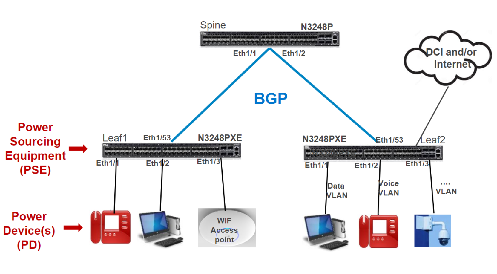
Figure 8. Deploying PoE end points at Enterprise SONiC edge
802.1x Port Access Control protocol
The Port Access Control (PAC) feature provides validation of client and user credentials to prevent unauthorized access to a specific switch port. PAC uses the following methods for client authentication:
- 802.1X─IEEE 802.1X-2004 is an IEEE Standard for PAC that provides an authentication mechanism to devices wanting to attach to a LAN. The standard defines Extensible Authentication Protocol Over LAN (EAPOL). The 802.1X standard describes an architectural framework in which authentication and consequent actions take place. It also establishes the requirements for a protocol between the authenticator and the supplicant, as well as between the authenticator and the authentication server.
- MAB─An authenticator can use MAC Authentication Bypass (MAB) feature to authenticate simple devices like cameras or printers that do not support 802.1x. The MAB feature uses the device MAC address to authenticate the client.
These methods in turn use RADIUS for client credential verification and receive the authorization attributes like VLANs and ACLs for the authenticated clients.
The PAC process includes several components, the clients (supplicants), the port access entity authenticator (SONiC Switch), and the authentication server (RADIUS). The RADIUS server allows to control user profiles and access control.
When a client authenticates itself initially on the network, the SONiC Switch acts as the authenticator to the clients on the network and forwards the authentication request to the Radius server in the network.
If the authentication succeeds, and then the client is placed in an authorized state and the client can forward or receive traffic through the port.
RADIUS servers send a list of Authorization attributes like VLAN and ACLs to be applied to the client traffic. This allows the flexibility of differential treatment to clients.
The PAC Port modes include:
- Auto Mode─This mode enforces authentication process on a port. The port state is unauthorized and blocked for traffic unless the client is authenticated.
- Force UnAuth─In this mode, the port is configured into an unauthorized state and blocks any client traffic.
- Force Auth─This mode is used to disable authentication on a port and all client traffic is allowed.
The Host modes determine the number of hosts that have access and the type of host, either voice or data to allow access. The PC Host modes include:
- Single-Host─Only one data client can be authenticated on a port and the client is granted access to the port. Access is allowed only for this client.
- Multi-Host─Only one data client can be authenticated on a port. When authentication succeeds, access is granted to all clients connected to the port.
- Multi-Auth─One voice client and multiple data clients can be authenticated on a port and these clients are and then granted access.
- Multi-Domain─One data client and one voice client can be authenticated on a port and these clients are then granted access.
Another part of Port Access Control is the special VLANs involved if the authentication method fails or times out. If the last authentication fails, the authentication manager can authorize the client to a special VLAN.
- UnAuth VLAN─This VLAN is used to authorize clients that fail authentication due to invalid credentials. It is used for 802.1X aware clients only.
- Guest VLAN─This VLAN is used to authorize 802.1X unaware clients.
- Monitor Mode─If Monitor mode is enabled, PAC places the client in Monitor mode as applicable.
- Open VLAN─Open Authentication capability allows PAC to allow client traffic events before it authenticates
Multiple Spanning Tree Protocol (MSTP)
MSTP is an extension to Rapid Spanning Tree Protocol (RSTP). MSTP further develops the usefulness of VLANs. MSTP configures a separate spanning tree for each VLAN group and blocks all but one possible alternate path within each spanning tree. MSTP allows formation of MST regions that can run multiple MST instances (MSTI). Multiple regions and other STP bridges are interconnected using one single common spanning tree (CST). Several VLANs can be mapped to a single spanning tree instance. Region plays a vital role to determine the VLAN to STP instance mapping. MST must be able to interact with 802.1q-based networks, because 802.1q is another IEEE standard. For 802.1q, a bridged network only implements CST. The IST instance is an RSTP instance that extends the CST inside the MST region.
Benefits
PVST and Rapid-PVST supported running a separate instance for each VLAN, which helped in load-balancing with multiple instances. However, this resulted in increased numbers of spanning-tree instances to be run, which meant a higher load on CPUs and scalability issues.
The Multiple spanning tree protocol is aimed at addressing these limitations by allowing multiple instances of spanning-tree with each instance having multiple VLANs assigned.
MSTP helps to reduce the overall number of spanning-tree instances that need to be run on a physical topology.
Multiple spanning-tree instances allow load-balancing of the traffic by each instance having different forwarding paths on a physical topology.