
Enterprise SONiC Edge Deployment
Enterprise SONiC Edge Deployment
-
This section provides the details about the underlying infrastructure used for the configuration in this deployment guide. This deployment guide uses a Layer 3 leaf-spine topology for the network underlay. The underlay provides transit for the virtual network overlays. Dell Networking PowerSwitch N3248X-ON are used at Spine Layer, and Dell Networking PowerSwitch N3248PXE-ON are used at Leaf Layer.
In rack 1, two N3248PXE-ON switches are configured as Multi Chassis link aggregation groups (MC-LAG) Peers. An MC-LAG provides redundancy and load balancing between the two MC-LAG peers, multihoming support, and a loop-free Layer 2 network without running STP. As administrators add racks to the data center, two leaf switches configured for MC-LAG can be added to each new rack. Connections within racks from hosts to leaf switches are Layer 2, and each host is connected using an MC-LAG port channel.
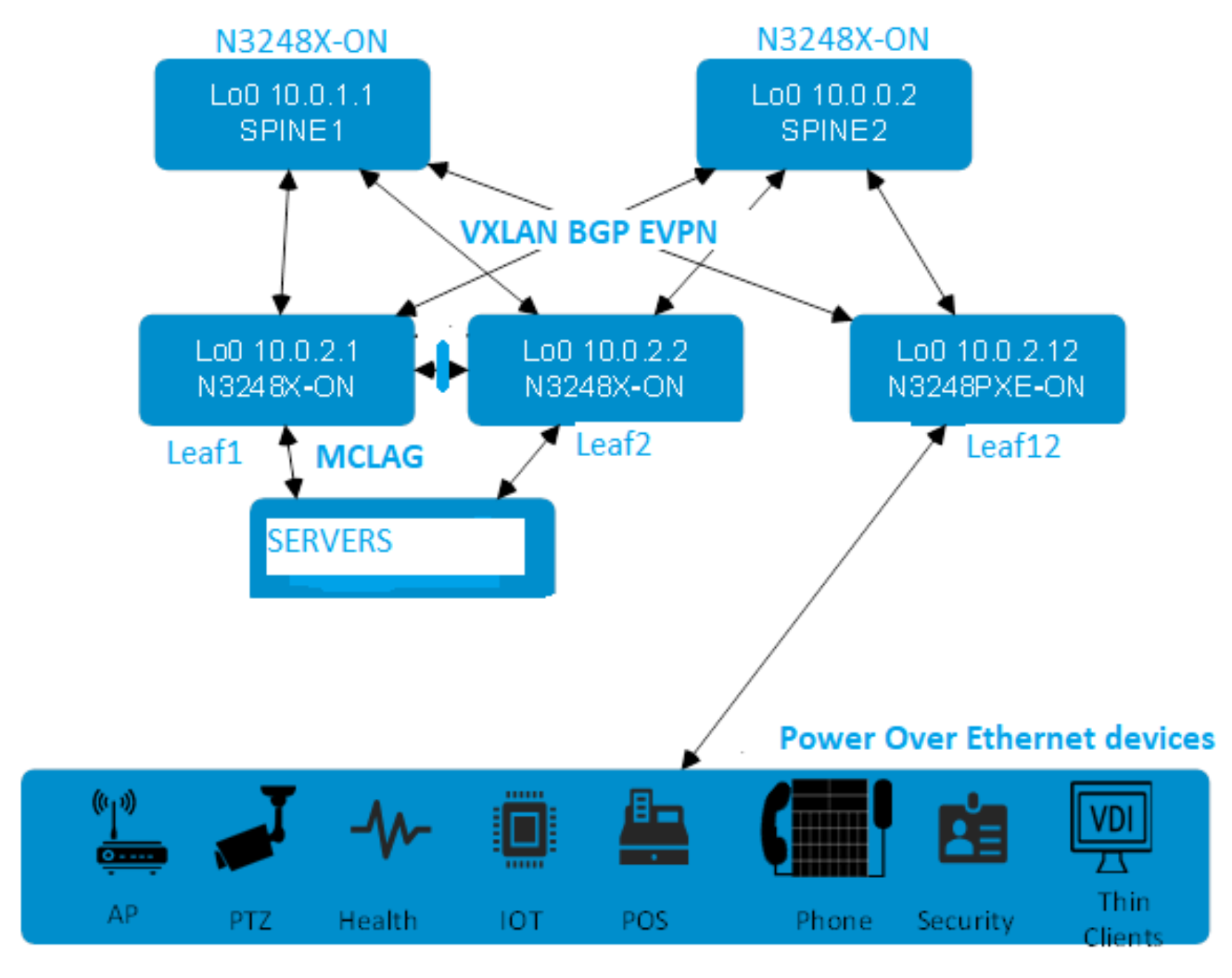
Figure 9. Enterprise Edge Deployment topology
eBGP is used as control plane between Leaf and Spine, an autonomous system number (ASN) is assigned to each switch. Valid private, 2-byte ASNs range from 64512 to 65534. ASNs should follow a logical pattern for ease of administration and allow for growth as additional leaf and spine switches are added. In this example, 65000 ASN represents the Spine Switches and ASN 65001-65027 represents the leaf switches.
Establishing a logical, scalable IP address scheme is important before deploying a leaf-spine topology. Loopback addresses may be used as router IDs when configuring routing protocols. As with ASNs, loopback addresses should follow a logical pattern that will make it easier for administrators to manage the network and allow for growth. In our given example, all the loopback addresses used are part of the 10.0.0.0/8 address space with each address using a 32-bit mask. In this example, the third octet represents the layer, “1” for spine and “2” for leaf. The fourth octet is the counter for the appropriate layer. For example, 10.0.1.1/32 is the first spine switch in the topology while 10.0.2.2/32 is the second leaf switch.
To exchange IP Prefixes, we used Unnumbered BGP. The Unnumbered BGP standard defined in the RFC 5549 no longer requires an IPv4 prefix to be advertised along with an IPv4 next hop. This means BGP peers can exchange IPv4 prefixes without having to configure an IPv4 address. The Unnumbered BGP feature works by discovering the peer routers that are attached to point-to-point links by parsing the Router-advertisements (RA).
VXLAN BGP EVPN overlay
In this deployment example, three VNIs are used: 600, 400, and 410. All VNIs are configured on three leaf switches. VNI 600 is used to carry Type-5 routes whereas VNI 1400 and VNI 500 are used to carry Type-2 routes. Because these VNIs have anycast gateways, VMs on those VNIs which are routing to other networks can use the same gateway information while behind different leaf pairs. When those VMs route, their local leaf switches will always be doing the routing. This enables VMs to migrate from one leaf pair to another without the need to change the network configuration. It also eliminates hair-pinning and improves link utilization since routing is performed closer to the source.
Switch preparation
The following table shows the hardware components that are used for the Enterprise SONiC edge bundle deployment:
Table 3. Hardware used in the deployment
Product name or model number
Notes or placement of products
N3248PXE-ON
1 / 2.5 / 5 GbE switches as leaf switches
N3248X-ON
10 GbE switches as spines
N3248TE-ON
1 GbE switches for OOB management traffic
VoIP phone
Camera with PoE port
WIFI controller with PoE
Linux /Windows server
Provides end-point attachment to the network.
Download firmware and OS
Go to Support for PowerSwitch N3200-ON Series | Drivers & Downloads to download Device Firmware and ONIE software for the N3200 series switches.
Go to Dell Digital Locker (DDL), log in with your Dell registered credentials, and select the latest Enterprise SONiC edge bundle entry:

Figure 10. Enterprise SONiC eSupport details
Installing SONiC
The deployment in this guide uses the switch serial port connected directly to a PC or laptop. The SONiC OS software was downloaded from the Dell Digital Locker and the firmware and ONIE files were downloaded from the Dell support site. The downloaded files are copied to a USB flash device and connected to the switch. The default serial port setting is 115200 baud, 8 data bits, 1 stop bit, no parity and xon/xoff flow control.
Update ONIE
To ensure the switch is running the current version of the ONIE NOS boot loader:
- Select ONIE option Rescue from the ONIE boot menu.
- Mount USB device: mount /dev/sdb1 /mnt/usb
- Change the directory to the mount point: cd /mnt/usb
- Update ONIE with the command:
onie-self-update onie-updater-x86_64-dellemc_n2200_n3200_c3338-r0.3.45.1.9-6
Switch will reboot on completion of the update.
Update firmware
- Select ONIE: Rescue from the ONIE boot menu.
- Mount USB device: mount /dev/sdb1 /mnt/usb
- Change the directory to the mount point: cd /mnt/usb
- Update firmware with the command:
onie-self-update onie-firmware-x86_64-dellemc_n2200_n3200_c3338-r0.3.45.5.1-26.bin
Remove existing OS
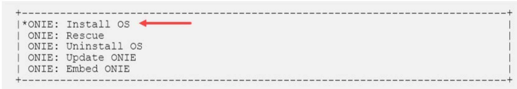
When you reboot the switches, a startup menu is displayed. Use the arrow keys on the keyboard to select the ONIE: Uninstall OS option, as shown in the following figure:

Install NOS
Select ONIE: Install OS from the ONIE boot menu.
- Mount USB device: mount /dev/sdb1 /mnt/usb
- Change the directory to the mount point: cd /mnt/usb
- Install SONiC with the command:
onie-nos-install Enterprise_SONiC_OS_4.0.1_Edge_Standard.bin
Initial Login
SONiC is ready to deploy. The default admin password is YourPaSsWoRd, and it must be changed on first boot.
sonic login: admin
Password:YourPaSsWoRd
You are required to change your password immediately (administrator enforced)
Changing password for admin.
Current password: YourPaSsWoRd
New password:
Retype new password:
Last login: Wed Jun 22 16:08:55 UTC 2022 on ttyS0
Linux sonic 4.19.0-9-2-amd64 #1 SMP Debian 4.19.118-2+deb10u1 (2020-06-07) x86_64
You are on
____ ___ _ _ _ ____
/ ___| / _ \| \ | (_)/ ___|
\___ \| | | | \| | | |
___) | |_| | |\ | | |___
|____/ \___/|_| \_|_|\____|
-- Software for Open Networking in the Cloud --
Unauthorized access and/or use are prohibited.
All access and/or use are subject to monitoring.
Help: http://azure.github.io/SONiC/
admin@sonic:~$
Activate command console
All commands in this guide will use the Management Framework command line interface.
admin@sonic:~$ sonic-cli
sonic#
Factory default configuration
The switch configuration commands in the chapters that follow begin with the leaf switches at their factory default settings. Dell PowerSwitches running SONiC can be reset to their default configuration as follows:
sonic# write erase
Existing switch configuration files except management interface configuration will be removed, continue? [y/N]:y
Configuration erase command will take effect on the next reboot.
sonic# reboot
Check switch OS version
Dell PowerSwitches must be running SONiC version 4.0 or later for this deployment. Run the show version command to check the OS version:
sonic# show version
Software Version : '4.0.1-Campus'
Product : Enterprise SONiC Distribution by Dell Technologies
Distribution : '10.12'
Kernel : '4.19.0-9-2-amd64'
Config DB Version : version_4_0_1
Build Commit : 'b81f07c4a'
Build Date : Fri May 27 07:53:36 UTC 2022
Built By : sonicbld@sonic-lvn-csg-003
Platform : x86_64-dellemc_n3248pxe_c3338-r0
HwSKU : DELLEMC-N3248PXE
ASIC : broadcom
Hardware Version : A01
Serial Number : TW0296F9DNT0024C0253
Uptime : 20:19:05 up 6 days, 4:05, 1 user, load average: 1.74, 1.67, 1.70
Mfg : Dell EMC
Management network
The OOB management network is isolated from the leaf-spine production network. It is the same for Layer 2 and Layer 3 leaf-spine topologies. N3248-TE installed in each rack provides 1 GbE connectivity to the management network.
The RJ-45 OOB management ports on each spine and leaf switch are connected to the N3248-TE switches.
PowerEdge server iDRACs and Chassis Management Controllers (CMCs) are also connected for server administration. A management network is not a requirement to configure or use a leaf-spine network, but is recommended to efficiently manage servers, switches, and storage devices.

Figure 11. Optional management network topology
Network configuration steps
This section presents the following topics:
Topics:
- Spine configuration steps
- Leaf1 and Leaf2 configuration steps
- Leaf12 configuration steps
- Verifying the environment
Spine configuration steps
Refer to the spine switches in the deployment topology. After login to the switch, the first step is to run the sonic-cli in the Linux mode to get access into the Management CLI command mode (MF-CLI) as shown below:
Spine1
Spine2
sonic-cli
configure terminal
interface-naming standard
sonic-cli
configure terminal
interface-naming standard
Spine1
Spine2
hostname SPINE1
end
exit
hostname SPINE2
end
exit
- Re-enter the MF-CLI and configuration mode.
- Assign a loopback interface with a unique router ID for each spine.
- Enable IPv6 on the spine downlinks to support unnumbered BGP point-to-point links and enable the interfaces.
Spine1
Spine2
sonic-cli
configure terminal
interface loopback 0
description router-id
ip address 10.0.1.1/32
exit
interface Eth 1/37
description "Down Link to Leaf1"
ipv6 enable
no shutdown
interface Eth 1/38
description "Down Link to Leaf2"
ipv6 enable
no shutdown
interface Eth 1/48
description "Down Link to Leaf12"
ipv6 enable
no shutdown
exit
sonic-cli
configure terminal
interface loopback 0
description router-id
ip address 10.0.1.2/32
exit
interface Eth 1/37
description "Down Link to Leaf1"
ipv6 enable
no shutdown
interface Eth 1/38
description "Down Link to Leaf2"
ipv6 enable
no shutdown
interface Eth 1/48
description "Down Link to Leaf12"
ipv6 enable
no shutdown
exit
- Configure the BGP router with ECMP enabled.
- Add the IPv4 unicast address-family to advertise the router-ID and paths for two leafs.
- Configure the BGP leaf peer-group. Set timers and enable unnumbered BGP and BFD.
- Activate IPv4 unicast for the peer group.
- Assign the leaf neighbor interfaces to the peer-group.
- Save the configuration.
Spine1
Spine2
router bgp 65000
router-id 10.0.1.1
bestpath as-path multipath-relax
address-family ipv4 unicast
redistribute connected
maximum-paths 2
exit
peer-group LEAF
advertisement-interval 5
timers 3 9
remote-as external
capability extended-nexthop
bfd
address-family ipv4 unicast
activate
exit
address-family l2vpn evpn
activate
exit
exit
neighbor interface Eth 1/37
peer-group LEAF
exit
neighbor interface Eth 1/38
peer-group LEAF
exit
neighbor interface Eth 1/48
peer-group LEAF
exit
exit
end
write memory
router bgp 65000
router-id 10.0.1.2
bestpath as-path multipath-relax
address-family ipv4 unicast
redistribute connected
maximum-paths 2
exit
peer-group LEAF
advertisement-interval 5
timers 3 9
remote-as external
capability extended-nexthop
bfd
address-family ipv4 unicast
activate
exit
address-family l2vpn evpn
activate
exit
exit
neighbor interface Eth 1/37
peer-group LEAF
exit
neighbor interface Eth 1/38
peer-group LEAF
exit
neighbor interface Eth 1/48
peer-group LEAF
exit
exit
end
write memory
Leaf1 and Leaf2 configuration steps
Leaf1 and Leaf2 are configured as an MCLAG pair. Refer to the deployment topology above.
- Enter Management Framework CLI (MF-CLI) and then configuration mode.
- Change the interface naming mode to Standard and add a hostname.
- Exit back to the Linux shell to activate the changes.
Leaf1
Leaf2
sonic-cli
configure terminal
interface-naming standard
hostname LEAF1
end
exit
sonic-cli
configure terminal
interface-naming standard
hostname LEAF2
end
exit
- Re-enter the MF-CLI and configuration mode.
- Assign a loopback interface with a unique router ID on each leaf.
- Then enable IPv6 on spine uplinks to support unnumbered BGP point-to-point links and enable the interfaces.
Leaf1
Leaf2
sonic-cli
configure terminal
interface loopback 0
description router-id
ip address 10.0.2.1/32
exit
interface Eth 1/37
description "Link to SPINE1"
ipv6 enable
no shutdown
interface Eth 1/38
description "Link to SPINE2"
ipv6 enable
no shutdown
exit
sonic-cli
configure terminal
interface loopback 0
description router-id
ip address 10.0.2.2/32
exit
interface Eth 1/37
description "Link to SPINE1"
ipv6 enable
no shutdown
interface Eth 1/38
description "Link to SPINE2"
ipv6 enable
no shutdown
exit
- Assign a VRF for each tenant. This deployment only has one tenant but will support multiple tenants with additional VRFs.
- Configure VLANs 50 and 140 for the hosts, bind to the tenant's VRF and assign the same anycast-address to each host VLAN.
- Assign a dedicated VLAN (Vlan60) for a L3 VNI and bind it to the tenant's VRF.
Leaf1
Leaf2
ip vrf Vrf-tenant1
interface Vlan 50
ip vrf forwarding Vrf-tenant1
ip anycast-address 192.168.50.254/24
neigh-suppress
exit
interface Vlan 140
ip vrf forwarding Vrf-tenant1
ip anycast-address 192.168.140.254/24
neigh-suppress
exit
interface Vlan 60
ip vrf forwarding Vrf-tenant1
exit
ip vrf Vrf-tenant1
interface Vlan 50
ip vrf forwarding Vrf-tenant1
ip anycast-address 192.168.50.254/24
neigh-suppress
exit
interface Vlan 140
ip vrf forwarding Vrf-tenant1
ip anycast-address 192.168.140.254/24
neigh-suppress
exit
interface Vlan 60
ip vrf forwarding Vrf-tenant1
exit
- Configure the MCLAG peer-link and port channel members.
- Configure all VLANs on the MCLAG's peer-link port channel.
Leaf1
Leaf2
interface Portchannel 100
description MCLAG-Peer-Link
switchport trunk allowed vlan add 50,60,140
exit
interface range Eth 1/49-1/50
description MCLAG-Peer-Link
channel-group 100
no shutdown
exit
interface Portchannel 100
description MCLAG-Peer-Link
switchport trunk allowed vlan add 50,60,140
exit
interface range Eth 1/49-1/50
description MCLAG-Peer-Link
channel-group 100
no shutdown
exit
Configure the MCLAG domain.
The loopback IP address used for the router-id is also used as the MCLAG source and peer IP address.
- Assign the host's port channel interfaces and assign to the MCLAG domain.
Leaf1
Leaf2
mclag domain 1
source-ip 10.0.2.1
peer-ip 10.0.2.2
peer-link PortChannel 100
delay-restore 90
exit
interface PortChannel 202
description "Host1 PortChannel"
switchport trunk allowed vlan add 50,140
mclag 1
exit
interface Eth 1/3
description Host
channel-group 202
no shutdown
exit
mclag domain 1
source-ip 10.0.2.2
peer-ip 10.0.2.1
peer-link PortChannel 100
delay-restore 90
exit
interface PortChannel 202
description "Host1 PortChannel"
switchport trunk allowed vlan add 50,140
mclag 1
exit
interface Eth 1/3
description Host
channel-group 202
no shutdown
exit
- Enable static anycast-address and assign a unique MAC to be used across all leaf switches.
- Create a loopback interface for the VTEP IP address. This address must be the same for each MCLAG peer.
- Create a VXLAN interface and assign the same VTEP source IP address to each peer.
- Assign a unique primary-ip to optimize routing for orphan ports and active-standby hosts. The router-id can be used for this purpose.
- Map the L2 VNI to the host VLANs that are stretched across the fabric.
- Create an L3 VNI by mapping the dedicated VLAN (Vlan60) to the non-default VRF.
Leaf1
Leaf2
ip anycast-address enable
ip anycast-mac-address 00:00:00:00:01:02
interface Loopback 1
description "Logical VTEP"
ip address 10.10.10.1/32
exit
interface vxlan vtep1
source-ip 10.10.10.1
primary-ip 10.0.2.1
map vni 1400 vlan 140
map vni 500 vlan 50
map vni 600 vlan 60
map vni 600 vrf Vrf-tenant1
exit
ip anycast-address enable
ip anycast-mac-address 00:00:00:00:01:02
interface Loopback 1
description "Logical VTEP"
ip address 10.10.10.1/32
exit
interface vxlan vtep1
source-ip 10.10.10.1
primary-ip 10.0.2.2
map vni 1400 vlan 140
map vni 500 vlan 50
map vni 600 vlan 60
map vni 600 vrf Vrf-tenant1
exit
- Configure the BGP router with ECMP enabled.
- Configure the underlay's address-family and redistribute the connected networks.
- Add VNI advertisements to the EVPN address family and assign the MCLAG peer's primary-ip.
Leaf1
Leaf2
router bgp 65001
router-id 10.0.2.1
bestpath as-path multipath-relax
address-family ipv4 unicast redistribute connected
maximum-paths 2
exit
address-family l2vpn evpn
advertise-all-vni
advertise-pip peer-ip 10.0.2.2
exit
router bgp 65001
router-id 10.0.2.2
bestpath as-path multipath-relax
address-family ipv4 unicast
redistribute connected
maximum-paths 2
exit
address-family l2vpn evpn
advertise-all-vni
advertise-pip peer-ip 10.0.2.1
exit
- Configure the BGP spine peer-group.
- Set timers and enable unnumbered BGP and BFD on the peer-group.
- Activate both IPv4 unicast and EVPN address families for the spine peer group.
- Set allowas-in to support MCLAG peer’s ASN to be received.
Leaf1
Leaf2
peer-group SPINE
advertisement-interval 5
timers 3 9
remote-as external
capability extended-nexthop
bfd
address-family ipv4 unicast
activate
allowas-in 1
exit
address-family l2vpn evpn
activate
exit
exit
peer-group SPINE
advertisement-interval 5
timers 3 9
remote-as external
capability extended-nexthop
bfd
address-family ipv4 unicast
activate
allowas-in 1
exit
address-family l2vpn evpn
activate
exit
exit
- Assign the spine neighbor interfaces to the peer-group.
- Create the BGP router for each tenant’s VRF.
- Save the configuration.
Leaf1
Leaf2
neighbor interface Eth 1/37
peer-group SPINE
exit
neighbor interface Eth 1/38
peer-group SPINE
exit
exit
router bgp 65001 vrf Vrf-tenant1
address-family ipv4 unicast
redistribute connected
exit
address-family l2vpn evpn
advertise ipv4 unicast
exit
exit
end
write memory
neighbor interface Eth 1/37
peer-group SPINE
exit
neighbor interface Eth 1/38
peer-group SPINE
exit
exit
router bgp 65001 vrf Vrf-tenant1
address-family ipv4 unicast
redistribute connected
exit
address-family l2vpn evpn
advertise ipv4 unicast
exit
exit
end
write memory
Leaf12 configuration steps
Enter Management Framework CLI (MF-CLI) and then configuration mode.
Change the interface naming mode to Standard, add hostname, save configuration, and exit back to the Linux shell to activate the changes.
Leaf12
!
sonic-cli
configure terminal
interface-naming standard
hostname LEAF12
end
write memory
exit
!
- Re-enter the MF-CLI and configuration mode.
- Assign a unique router ID on each leaf.
- Then enable IPv6 on spine uplinks to support unnumbered BGP point-to-point links and enable the interfaces.
Leaf12
!
sonic-cli
configure terminal
interface loopback 0
description router-id
ip address 10.0.2.25/32
Exit
interface Eth 1/47
description "Link to SPINE1"
ipv6 enable
no shutdown
interface Eth 1/48
description "Link to SPINE2"
ipv6 enable
no shutdown
exit
!
- Assign a VRF for each tenant. This deployment only has one tenant but will support multiple tenants with additional VRFs.
- Configure VLANs 80 and 140 for the hosts, bind to the tenant’s VRF and assign the same anycast-address to each host VLAN.
- Assign a dedicated VLAN (Vlan60) for a L3 VNI and bind it to the tenant’s VRF.
Leaf12
ip vrf Vrf-tenant1
interface Vlan 80
ip vrf forwarding Vrf-tenant1
ip anycast-address 192.168.80.254/24
neigh-suppress
exit
interface Vlan 140
ip vrf forwarding Vrf-tenant1
ip anycast-address 192.168.140.254/24
neigh-suppress
exit
interface Vlan 60
ip vrf forwarding Vrf-tenant1
exit
- Enable static anycast-address and assign a unique MAC to be used across all leaf switches.
- Create a loopback interface for the VTEP IP address. This address must be the same for each MCLAG peer.
- Create a VXLAN interface and assign the same VTEP source IP address to each peer.
- Assign a unique primary-ip to optimize routing for orphan ports and active-standby hosts. The router-id can be used for this purpose.
- Map the L2 VNI to the host VLANs that are stretched across the fabric.
- Create a L3 VNI by mapping the dedicated VLAN (Vlan60) to the non-default VRF. The Network Virtualization Overlay (NVO) is automatically assigned to the VXLAN interface.
Leaf12
ip anycast-address enable
ip anycast-mac-address 00:00:00:00:01:02
interface Loopback 1
description "Logical VTEP"
ip address 10.10.10.25/32
Exit
interface vxlan vtep25
source-ip 10.10.10.25
primary-ip 10.0.2.25
map vni 1400 vlan 140
map vni 500 vlan 50
map vni 600 vlan 60
map vni 600 vrf Vrf-tenant1
exit
- Configure the BGP router with ECMP enabled.
- Configure the underlay’s address-family and redistribute the connected networks.
- Add VNI advertisements to the EVPN address family and assign the MCLAG peer’s primary-IP as router-id
Leaf12
router bgp 65025
router-id 10.0.2.25
bestpath as-path multipath-relax
address-family ipv4 unicast
redistribute connected
maximum-paths 2
exit
- Configure the BGP spine peer-group.
- Set timers and enable unnumbered BGP and BFD on the peer-group.
- Activate both IPv4 unicast and EVPN address families for the spine peer group.
Leaf12
peer-group SPINE
advertisement-interval 5
timers 3 9
remote-as external
capability extended-nexthop
bfd
address-family ipv4 unicast
activate
exit
exit
- Assign the spine neighbor interfaces to the peer-group.
- Create the BGP router for each tenant’s VRF.
- Save the configuration.
Leaf12
neighbor interface Eth 1/47
peer-group SPINE
exit
neighbor interface Eth 1/48
peer-group SPINE
exit
exit
router bgp 65025 vrf Vrf-tenant1
address-family ipv4 unicast
redistribute connected
exit
address-family l2vpn evpn
advertise ipv4 unicast
exit
exit
end
write memory
!
Leaf12 hosts 1G PoE-enabled camera equipment connected to Eth1/24. The following lines would enable the PoE on the switch and provide power to the connected camera. In general, we set the PoE power management to dynamic and the threshold to 90% of the maximum power. At the interface level based on the type of end device connected, we enable PoE. This would take care of providing power. But there are other parameters if needed that can be set to enable more specific needs.
The following are the steps to enable PoE for an end device.
- Global level:
- Set the PoE power management reservation to dynamic
- Set the PoE power usage threshold to 90%
- Interface level:
- Enable PoE on the interface. PoE is disabled by default.
- Set the PoE priority level
- Set the interface to advertise power management lldp tlv
Leaf12
poe power management dynamic
poe usage-threshold 90
interface Eth 1/24
description “PoE Camera on this port”
mtu 9100
speed 1000
no poe disable
poe priority high
lldp med-tlv-select power-management
no shutdown
exit
write memory
The following configuration would enable DOT1X protocol to authenticate and authorize the connected end device attached to the switch port. A Windows server on port Eth1/22 will be authenticated using DOT1x and a PoE camera on eth1/24 port with MAB. The authentication and authorization when successful would enable traffic flow for the end device. Cisco ISE is the most common authentication server used. FreeRadius and Aruba Clearpass are the other two validated by Enterprise SONiC Edge.
The following are the steps involved:
- Global Config:
- Enable 802.1x authentication on the switch.
- Interface level:
- Configure a VLAN as a guest VLAN on the interface.
- Configure a VLAN as the unauthenticated VLAN on the interface.
- Set the maximum number of clients supported on the interface.
- Enable periodic reauthentication of the supplicant for the specified interface.
- Set the authentication mode to use on the specified interface.
- Configure the host mode of a port.
- Configure the reauthentication time period.
- Set the order of the authentication methods to use.
- Set the priority for the authentication methods to be used.
- Enable dot1x on port as pae authenticator.
Leaf12
dot1x system-auth-control
interface Vlan 30
description “dot1x guest vlan”
exit
interface Vlan 31
description “unauthenticated vlan”
exit
interface Eth 1/22
Description “dot1x supplicant on windows 10 box”
switchport access vlan 50
authentication max-users 3
authentication host-mode multi-auth
authentication port-control auto
authentication event no-response action authorize vlan 31
authentication event fail action authorize vlan 30
authentication order dot1x mab
authentication priority dot1x mab
authentication periodic
dot1x pae authenticator
mab
spanning-tree port type edge
interface Eth 1/24
Description “PoE camera”
switchport access vlan 50
authentication max-users 1
authentication host-mode single-host
authentication port-control auto
authentication event no-response action authorize vlan 31
authentication event fail action authorize vlan 30
authentication order mab
authentication priority mab
authentication periodic
mab
spanning-tree port type edge
exit
write memory
The radius server configuration for PAC is shown below.
The host specified is the Cisco ISE domain IP address. Cisco ISE is a tool used for authenticating and authorizing end points connecting to leaf Ethernet ports. The detailed information about how this tool is integrated with the SONiC fabric is out of scope in this current version of the document. It will be covered in the next update to this document.
The following shows the switch side configuration of Cisco ISE:
Leaf12
aaa authentication login default group radius local
aaa authentication failthrough enable
radius-server timeout 5
radius-server auth-type pap
radius-server host ise.dnse.com auth-port 1812 key dell123 priority 64 source-interface Management 0
write memory