
Networking
Networking
-
PowerStore X model appliances have a vSphere Distributed Virtual Switch (DVS), multiple port groups, and NIC teaming that is configured automatically as part of the initial configuration process. The DVS has a naming convention of DVS-<Cluster_Name>. Then, the DVS name is prepended to each port group name, along with a dash.
The DVS has the following port groups created, by default:
- PG_MGMT: PowerStore management
- PG_MGMT_ESXi: ESXi management
- PG_Storage_INIT1 - 2: VMkernel adapters for iSCSI connectivity from ESXi to the controller VM
- PG_Storage_TGT1 - 4: iSCSI targets on the controller VM for internal and external connectivity
- PG_vMotion1: vMotion network used for VM mobility
The vSphere DVS groups the physical adapters from both nodes together into uplinks. The uplinks are used on each of the port groups to indicate which ports are active, standby, or unused. The following table shows the mapping between the vSphere uplink, vSphere physical adapter, and PowerStore Manager port names:
Table 2. Uplink to physical port mappings
vSphere Uplink
vSphere Physical Adapter
PowerStore Manager Port
Uplink1
vmnic8
4PortCard-hFEPort1
Uplink2
vmnic9
4PortCard-hFEPort0
Uplink3
vmnic6
4PortCard-hFEPort3
Uplink4
vmnic7
4PortCard-hFEPort2
The PowerStore X model ESXi node management interface is configured on a VMkernel adapter named vmk0. Because the PowerStore management interface resides on the controller VM, it does not require a VMkernel adapter.
Table 3. Management port group uplinks
vSphere
VMkernel AdaptervSphere
Port GroupvSphere
Active UplinksvSphere
Standby UplinksN/A
PG_MGMT
Uplink2
Uplink1Uplink3
Uplink4vmk0
PG_MGMT_ESXi
Uplink2
Uplink1Uplink3
Uplink4The following table shows the VMkernel adapters that are created for storage connectivity. The PowerStore X model ESXi nodes use these VMkernel adapters to connect to the iSCSI targets on the controller VMs. There are two VMkernel adapters on each node for multipathing purposes. The VMkernel adapters are active on one uplink and there are no standby uplinks.
The communication between the node and controller VM is used to establish iSCSI sessions, create protocol endpoints, and run I/O to the vVol datastore. Because the controller VM runs on the node itself, the traffic on these networks remains local to the node.
Table 4. VMkernel adapters
vSphere VMkernel Adapter
vSphere Port Group
vSphere Active Uplink
vmk1
PG_Storage_INIT1
Uplink1
vmk2
PG_Storage_INIT2
Uplink2
The following table shows the controller VM iSCSI targets that are created. These targets enable both the PowerStore X model ESXi node and external hosts to establish iSCSI connectivity. A minimum of one per node is required, which is configured automatically as part of the initial configuration process. By default, this target is active on Uplink1 on each node. The remaining uplinks are configured in standby mode.
Table 5. Controller VM iSCSI targets
vSphere Port Group
vSphere Active Uplink
vSphere Standby Uplinks
PG_Storage_TGT1
Uplink1
Uplink2
Uplink3
Uplink4PG_Storage_TGT2
Uplink2
Uplink1
Uplink3
Uplink4PG_Storage_TGT3
Uplink3
Uplink1
Uplink2
Uplink4PG_Storage_TGT4
Uplink4
Uplink1
Uplink2
Uplink3The storage network can be scaled out to enable connectivity on the remaining ports on the four-port card. When this action is done, the additional uplinks become active, as shown in the preceding table. Depending on the model appliance, this action may be a best practice for maximum performance.
The following table shows information about the virtual ports that are available on the appliance. The virtual ports page can be used to map additional ports for the storage network or tag additional ports for the replication network. By default, vFEPort1 is tagged for both storage and replication.
Table 6. PowerStore virtual ports
PowerStore Manager Virtual Port
vSphere
Network AdaptervSphere Port Group
Purpose
vFEPort0
Network adapter 1
PG_MGMT
PowerStore management
vFEPort1
Network adapter 2
PG_Storage_TGT1
Storage and replication network
vFEPort2
Network adapter 3
PG_Storage_TGT2
Storage and replication network scaling
vFEPort3
Network adapter 4
PG_Storage_TGT3
Storage and replication network scaling
vFEPort6
Network adapter 5
PG_Storage_TGT4
Storage and replication network scaling
vFEPort7
Network adapter 6
PG_Internal
Internal system use
The following table shows the VMkernel adapters that are created for vMotion operations. This network is used when moving VMs between the two PowerStore X model ESXi nodes and from external hosts.
Table 7. vMotion port group uplink
vSphere VMkernel Adapter
vSphere Port Group
vSphere
Active UplinksvSphere
Standby Uplinksvmk3
PG_vMotion1
Uplink3
Uplink1
Uplink2
Uplink4The following figure shows these networks as they appear in vCenter:
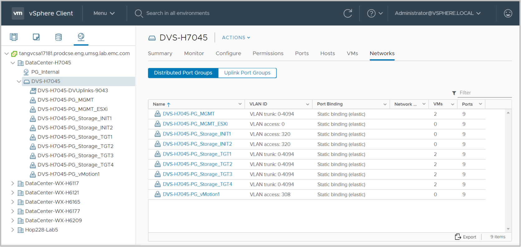
Figure 31. vSphere networks
Before deploying a user VM on the internal ESXi nodes, create a new port group for the external network. To complete the process, right-click DVS and select Distributed Port Group > New Distributed Port Group. Provide the information for the new port group and configure a VLAN, if necessary. After the new port group is configured, user VMs can be deployed and can use this port group for network connectivity.
If the PowerStore X model ESXi node, iSCSI, or vMotion interfaces must change, they must be updated in PowerStore Manager. This action updates the configuration and propagates the necessary changes to vSphere automatically. Changing these interfaces directly in vSphere is not supported.