
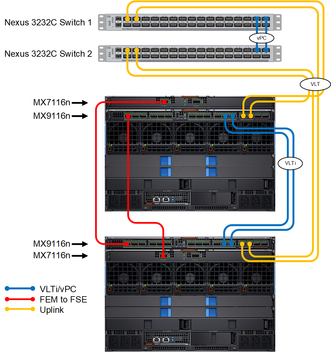
The figure below shows a topology using a pair of Cisco Nexus 3232C as leaf switches, but other Cisco Nexus switches may be used. This section details configuration of the Cisco Nexus switch with Ethernet - No Spanning Tree uplink, validation of the topology with Cisco Nexus switches, and creation of a SmartFabric with the corresponding uplinks.
Configure SmartFabric
Perform the following steps to configure SmartFabric:
- Physically cable the MX9116n FSE to the Cisco Nexus upstream switch. Make sure that chassis are in a Multi-Chassis Management group. For instructions, find the relevant version of the User Guide in the OME-M and OS10 compatibility and documentation table.
- Define VLANs to use in the Fabric. For instructions, see Define VLANs.
- Create the SmartFabric as per instructions in Create the SmartFabric.
- Configure uplink port speed or breakout. For more instructions, see Configuring port speed and breakout.
- After the SmartFabric is created, create the Ethernet - No Spanning Tree uplink. See Create Ethernet – No Spanning Tree uplink for more information.
- Set MX I/O modules global spanning tree configurations to Rapid Spanning Tree Protocol (RSTP).
- Create and deploy the appropriate server templates to the compute sleds. See Server Deployment for more information.
Cisco Nexus 3232C switch configuration
The following section outlines the configuration commands that are issued to the Cisco Nexus 3232C leaf switches with Ethernet - No Spanning Tree uplink connected from MX9116n FSE to the Cisco Nexus switch.
The switches start at their factory default settings, as described in Reset Cisco Nexus 3232C to factory defaults.
There are four steps to configure the 3232C upstream switches:
- Set switch hostname, management IP address, enable features vPC, LLDP, LACP, and interface-vlan.
- Configure vPC between the switches.
- Configure the VLANs.
- Configure the downstream port channels to connect to the MX switches.
Enter the following commands to set the hostname and enable required features. Configure the management interface and default gateway. Also run the global setting commands for Spanning Tree Protocol as mentioned in the following.
| Cisco Nexus 3232C Leaf 1 | Cisco Nexus 3232C Leaf 2 |
| |
Enter the following commands to create a virtual port channel (vPC) domain and assign the keepalive destination to the peer switch management IP. Then create a port channel for the vPC peer link and assign the appropriate switchport interfaces.
| Cisco Nexus 3232C Leaf 1 | Cisco Nexus 3232C Leaf 2 |
| |
Configure the required VLANs on each switch. In this deployment example, the Tagged VLAN used is VLAN 10 and Untagged VLAN used is VLAN 1. Disable spanning tree on VLANs.
| Cisco Nexus 3232C Leaf 1 | Cisco Nexus 3232C Leaf 2 |
| |
Enter the following commands to configure the port channels to connect to the downstream MX9116n FSEs. Then, exit configuration mode and save the configuration. Disable spanning tree on the port channel connected to MX9116n FSE.
| Cisco Nexus 3232C Leaf 1 | Cisco Nexus 3232C Leaf 2 |
| |
Trunk ports on switches allow tagged traffic to traverse the links. All flooded traffic for the VLAN is sent across trunk ports to all the switches, even if those switches do not have an associated VLAN. This takes up the network bandwidth with unnecessary traffic. VLAN or VTP Pruning is the feature that can be used to eliminate this unnecessary traffic by pruning the VLANs.
Pruning restricts the flooded traffic to only those trunk ports with associated VLANs to optimize the usage of network bandwidth. If the existing environment is configured for Cisco VTP or VLAN pruning, ensure that the Cisco upstream switches are configured appropriately. See the Cisco Nexus 3000 Series NX-OS Configuration Guide for additional information.
switchport trunk allow vlan all on the Cisco interfaces. The VLANs must be explicitly assigned to the interface. Configuration validation
This section covers the validation of the Cisco Nexus 3232C leaf switches. For information about the Dell Networking MX switch validation commands, see Common CLI troubleshooting commands for Full Switch and SmartFabric modes.
show vpc
The show vpc command validates the vPC configuration status. The peer adjacency should be OK, with the peer should show as alive. The end of the command shows which VLANs are active across the vPC.
NX3232C-Leaf1# show vpc
Legend:
                (*) - local vPC is down, forwarding via vPC peer-link

vPC domain id                     : 255
Peer status                       : peer adjacency formed ok
vPC keep-alive status             : peer is alive
Configuration consistency status  : success
Per-vlan consistency status       : success
Type-2 inconsistency reason       : Consistency Check Not Performed
vPC role                          : secondary, operational primary
Number of vPCs configured         : 1
Peer Gateway                      : Disabled
Dual-active excluded VLANs        : -
Graceful Consistency Check        : Enabled
Auto-recovery status              : Disabled
Delay-restore status              : Timer is off.(timeout = 30s)
Delay-restore SVI status          : Timer is off.(timeout = 10s)

vPC Peer-link status
---------------------------------------------------------------------
id   Port   Status Active vlans
--   ----   ------ --------------------------------------------------
1    Po255  up     1,10


vPC status
----------------------------------------------------------------------
id   Port   Status Consistency Reason                     Active vlans
--   ----   ------ ----------- ------                     ------------
255  Po1    up     success     success                    1,10
show vpc consistency-parameters
The show vpc consistency-parameters command displays the configured values on all interfaces in the vPC. The displayed configurations are only those configurations that limit the vPC peer link and vPC from coming up.
NX3232C-Leaf1# show vpc consistency-parameters vpc 255
Legend:
Type 1 : vPC will be suspended in case of mismatch

Name                        Type  Local Value            Peer Value
-------------               ----  ---------------------- -----------------------
STP Port Type               1     Normal Port            Normal Port
STP Port Guard              1     Default                Default
STP MST Simulate PVST       1     Default                Default
lag-id                      1     [(1000,                [(1000,
                                  20-4-f-0-cd-1e, 1, 0,  20-4-f-0-cd-1e, 1, 0,
                                  0), (7f9b,             0), (7f9b,
                                  0-23-4-ee-be-ff, 80ff, 0-23-4-ee-be-ff, 80ff,
                                   0, 0)]                 0, 0)]
mode                        1     active                 active
delayed-lacp                1     disabled               disabled
Speed                       1     100 Gb/s               100 Gb/s
Duplex                      1     full                   full
Port Mode                   1     trunk                  trunk
Native Vlan                 1     1                      1
MTU                         1     1500                   1500
Dot1q Tunnel                1     no                     no
Switchport Isolated         1     0                      0
vPC card type               1     N9K TOR                N9K TOR
Allowed VLANs               -     1,10                   1,10
Local suspended VLANs       -     -                      -
show lldp neighbors
The show lldp neighbors command provides information about lldp neighbors. In this example, Eth1/1 and Eth1/3 are connected to the two MX9116n FSEs, C160A2 and C140A1. The remaining links, Eth1/29 and Eth1/31, represent the vPC connection.
NX3232C-Leaf1(config)# show lldp neighbors
Capability codes:
  (R) Router, (B) Bridge, (T) Telephone, (C) DOCSIS Cable Device
  (W) WLAN Access Point, (P) Repeater, (S) Station, (O) Other
Device ID                Local Intf      Hold-time  Capability  Port ID
S3048-ON                 mgmt0           120        PBR         ethernet1/1/45
C160A2                   Eth1/1          120        PBR         ethernet1/1/41
C140A1                   Eth1/3          120        PBR         ethernet1/1/41
NX3232C-Leaf2            Eth1/29         120        BR          Ethernet1/29
NX3232C-Leaf2            Eth1/31         120        BR          Ethernet1/31
Total entries displayed: 5
show smartfabric uplinks
The show smartfabric uplinks command is used to verify the uplinks configured across the nodes in the fabric. This displays name, description, id, media type, native vlan, configured interfaces, and network profile associated with fabric. Run this command on MX9116n FSE. The following output shows that the uplink created is an Ethernet - No Spanning Tree uplink.
MX9116n-A1# show smartfabric uplinks
----------------------------------------------------------
Name                  : Uplink 1
Description           :
ID                    : 3d4f2222-f082-43c1-b034-b14a8df3a172
Media Type            : Ethernet - No Spanning Tree
Native Vlan           : 1
Untagged-network      :
Networks              : 9418125b-5f1f-48d7-8b5d-648b0977c643
Configured-Interfaces : 87QNMR2:ethernet1/1/41, 87QNMR2:ethernet1/1/42 8XRJ0T2:ethernet1/1/41, 8XRJ0T2:ethernet1/1/42
----------------------------------------------------------