


Direct from Development – PowerEdge MX and Intel QAT
Wed, 11 Nov 2020 12:36:28 -0000
|Read Time: 0 minutes
Summary
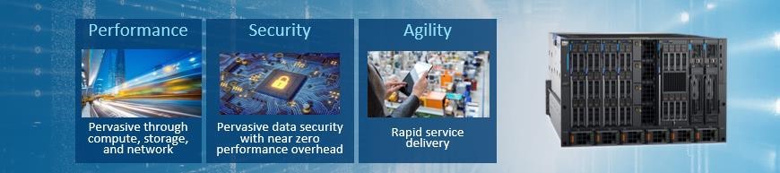
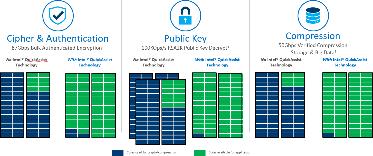
PowerEdge MX is the first Dell EMC server to offer a software licensing option to enable Intel® QuickAssist Technology. It provides a software-enabled foundation for security, authentication, and compression, and significantly increases the performance and efficiency of standard platform solutions. Intel QAT on PowerEdge MX servers offer performance across applications. That includes symmetric encryption and authentication, asymmetric encryption, digital signatures, RSA, DH, and ECC, and lossless data compression.

Encryption and Key Generation
Many users will be familiar with the “https” prefix on frequently-visited websites. Behind all of these secure websites is an implementation of TLS (transport layer security) or its predecessor SSL (secure sockets layer). Each protocol entails a “handshake” between the client and server that establishes authenticity of the server and creates a session key for encrypting the exchanged data. These Public Key Encryption (PKE) algorithms, historically performed by software, can be offloaded from the CPU into the Intel® QAT engine for providing significant performance gains for Web Server, eCommerce, VPN, Firewall or Security Load Balancer and Wan Acceleration solutions.
Data Compression and Decompression
Users of “zip” files will be familiar with the benefit of another common software function, data compression. Like cryptography, compression and decompression can be compute-intensive functions. Intel® QAT is comprised of acceleration engines for data compression as well, yielding faster performance and higher throughput for software and systems that rely on compressed data such as storage, web compression, big data, or high performance computing (HPC).
Benefit of Intel® QAT
It really boils down to the TCO, or total cost of ownership. A web server, cloud load balancer, or security gateway that can handle significantly more secure connections per second and provide high performance encrypted data throughput for reduced infrastructure cost. A storage system that uses accelerated compression to decrease the total required capacity vastly reduces storage footprint and subsequent costs. Application efficiency also reduces the thermal footprint of a datacenter or computing cluster, lowering energy costs. Improved efficiency and reduced active power for security and compression translate to reduced infrastructure.
Supported Operations
- Symmetric (Bulk) Cryptography
- Ciphers (AES, 3DES/DES, RC4, KASUMI*, ZUC, Snow 3G)
- Message digest/hash (MD5, SHA1, SHA2, SHA3) and authentication (HMAC, AES-XCBC)
Supported Operations (cont)
- Algorithm chaining (one cipher and one hash in a single operation)
- Authenticated encryption (AES-GCM, AES-CCM)
- AES-XTS
- Wireless
- KASUMI, Snow 3G and ZUC in encryption and authentication modes
- Asymmetric (Public Key) Cryptography
- Modular exponentiation for Diffie-Hellman (DH)
- RSA key generation, encryption/decryption and digital signature generation/verification
- DSA parameter generation and digital signature generation/verification
- Elliptic Curve Cryptography: ECDSA, ECDHE, Curve25519, SM2
- Compression/Decompression DEFLATE (Lempel-Ziv77) & Huffman.
Introducing Optional Software Licenses for Intel® QAT in PowerEdge MX
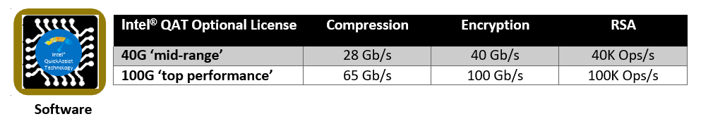
Intel® QAT has a long history with the deliveries of the 8920 model and the subsequent 8955 on PCIe cards. In the Intel® Xeon® Processor Scalable Family, Intel® is making the next generation of Intel® QAT available with significantly improved performance in a chipset-integrated version. Dell EMC is offering hardware-enabling licenses for chipset Intel® QAT on the MX series blade servers (MX740c and MX840c). These licenses can be installed without the need to add hardware to the system and occupy slots. Depending on the license level installed and the performance level desired, the chipset based Intel® QAT will be programmed to offer the bandwidth performance as defined below, mimicking the performance of the latest model 8960 and model 8970 PCIe cards. The licenses are installed through the iDRAC license manager.
Software is provided through the Intel open source site https://01.org/intel-quickassist-technology. The applicable drivers are associated with the C62x chipset. Application and library examples are posted here along with the API reference manuals, allowing users to build upon these open source libraries and examples or build their own applications. Release notes identify operating system compatibility.
Openssl
Openssl is a software library that implements cryptographic functions that secure communications over computer networks. It implements the aforementioned protocols SSL and TLS. OpenSSL versions 1.1.0 and beyond now have asynchronous support for hardware accelerators, which helps achieve power, performance, cost, capacity and efficiency benefits discussed above. Prior to this support, all cryptographic function calls were performed in a synchronous manner, which meant that any given CPU thread was “blocked” awaiting the result of an operation. With asynchronous operation, several operations can be queued for Intel® QAT engine, and the responses can be collected and consumed as soon as they are completed in rapid succession. The following resources describe how to get Intel® QAT working with openssl:
- https://www.openssl.org/source/
- https://github.com/01org/QAT_Engine
- https://github.com/openssl/openssl
Instructions to use openssl to integrate with applications such as NGINX web server and HAProxy, a load balancer and proxy, can be found on https://01.org/intel-quickassist-technology. NGINX has been demonstrated to handle more connections per second with the benefit of Intel® QAT.
DPDK (Data Plane Development Kit)
An open source project consisting of a set of libraries and drivers for fast packet processing, DPDK employs PMDs (Poll Mode Drivers) to interact with user space software, avoiding latency expensive context switches between kernel and user space. Instructions on installing the Intel® QAT PMD can be found at DPDK GUIDES LINK. Using DPDK, performance benefit has been demonstrated for IPsec (Internet Protocol Security), which provides security at a lower level in the protocol stack than TLS. For further reading on IPSEC, see the links Getting Started Guidehttps://software.intel.com/en-us/articles/get-started-with-ipsec-acceleration-in-the-fdio-vpp-project Sample Application Usage https://doc.dpdk.org/guides-16.04/sample_app_ug/ipsec_secgw.html.
Compression and Decompression
The primary vehicle for delivering sample code for data compression and decompression for Linux is QATZip, which is a user space library that produces data in standard gzip format. See the most recent release notes for the drivers and the API application guides for more information on data compression.
Intel® Key Protection Technology (Intel® KPT)
Inside the Intel chipset, there is a path for delivering keys directly from the key store in the chipset to the Intel® QAT engines. Software applications can utilize Intel® KPT to manage secure asymmetric and private key transactions for applications such as Hardware Security Modules(HSM) or Security Middle Box solutions.
Performance
Server workload performance is dependent on a wide variety of factors. The amount of CPU load on the system, the number of cores, the amount of memory, packet sizes, and compression levels are among many of such factors. Dell recommends specific testing to determine the exact improvements realizable by this offload. Below are some expected performance enhancements according to testing conducted Intel(r) Xeon Processor Scalable Family & Intel(r) C627 Chipset.
Crypto
NGINX* and OpenSSL* connections/second. Conducted by Intel Applications Integration Team. Claim is actual performance measurement. Intel® microprocessor. Processor: Intel® Xeon® processor Scalable family with C6xxB0 ES2
Performance tests use cores from a single CPU, Memory configuration:, DDR4–2400. Populated with 1 (16 GB) DIMM per channel, total of 6 DIMMs Intel® QuickAssist Technology driver: QAT1.7.Upstream.L.0.8.0-37 Fedora* 22 (Kernel 4.2.7) BIOS:
PLYDCRB1.86B.0088.D09.1606011736
Compression
24 Core Intel(r) Xeon Scalable Platform -SP @1.8GHz, Single (UP) Processor configuration. Intel(r) C627 PCH with crypto acceleration capability (in x16 mode) Neon City platform. DDR4 2400MHz RDIMMs 6x16GB(total 96 GB), 6 Channels, 1 x Intel® Corporation Red Rock Canyon 100GbE Ethernet Switch in the x16 PCIe slot on Socket 0. 8 cache ways allocated for DDIO.
Related Blog Posts

Direct from Development – PowerEdge MX7000 At the Box Serial Access
Thu, 12 Nov 2020 19:26:21 -0000
|Read Time: 0 minutes
Summary
PowerEdge MX7000 comes with a Management Module that provides chassis management. This technical white paper describes the step by step “at- the-box” serial access feature of the chassis management firmware. A typical use of the serial access feature is for troubleshooting purpose when remote access to the management firmware is not available.
Preparation
What you need?
To prepare for serial access, you need the correct cable for connection. You will need a “micro-USB to USB” cable (Figure-1) long enough to connect your client system to the micro-USB port in the Management Module.
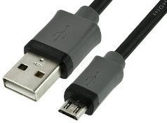
Figure 1 USB to Micro USB Cable
Where to connect?
The micro-USB port (Figure-2) for serial access is in the Management Module located at the rear of the chassis. If you see two Management Modules, look for the module that has the LED under “i” lit.
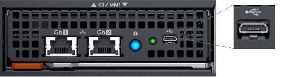
Figure 2 - Micro USB port to connect to
What you need in the client?
You can use any serial terminal client application of your choice, such as Tera Term or PuTTY.
Windows Client Host
If your client host system is running Windows, the default serial device driver should work. Open the Device Manager (type “devmgmt.msc” from command line) to determine which COM port Windows has created for your serial connection.
If Windows is not able to see the serial COM port or it is present but you are not able to connect, you may have to manually install the device driver. You can get this driver from a 3rd party vendor. Search for “cypress semiconductor usb serial driver download”. Look for the driver download link. After the manual driver installation, you should see the COM port for your connection (example in Figure-3).
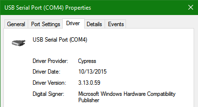
Figure 3 – 3rd party serial device driver in Windows
Linux Client Host
If your client host system is running Linux, the device driver to connect to the serial interface should already be installed. There is an extra step however that is required to correctly recognize the Management Module serial device.
The USB serial device is recognized by Linux as a “Thermometer” device and loads the cytherm kernel module. The following steps help to correctly recognize the Management Module serial device.
First, add this entry “blacklist cytherm” to the file “/etc/modprobe.d/blacklist.conf”. This will prevent loading the incorrect driver.
Next, connect the serial cable to the host system. If you have already connected the serial cable, you will need to unload the incorrect driver with the command “sudo rmmod cytherm”. Then re-connect the serial cable to the host system.
If you see “/dev/ttyACM0” then you are ready to connect. The “0” means it is the first serial device discovered.
Serial Console
Serial Console Menu
When a serial connection is established to the Management Module, the serial client application will be presented with the serial console’s main menu (Figure-4). It is populated with the available components to which serial connection can be made. On the upper right corner of the menu, it shows which Management Module you are connected to (the Active or the Standby). When you are finished, you may simply disconnect the cable and exit the serial client application.
The following sections describe each selection in the Main menu.
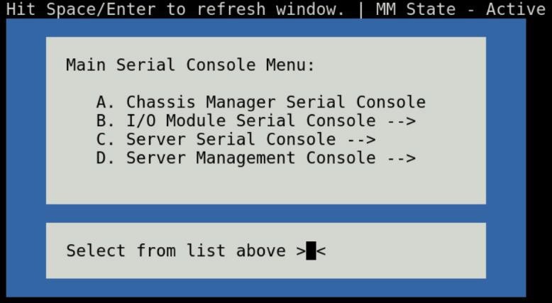
Figure 4 - Main menu
Chassis manager firmware console
Choosing option (A) from the Main menu takes you to the Chassis Manager firmware console. A serial session will open and a login prompt is displayed.
On successful login, you will have access to the Chassis Manager’s firmware racadm interface. To end the session, the exit sequence is “Ctrl-A Ctrl-X”. If using minicom in Linux, the exit sequence is “Ctrl-A Ctrl-A Ctrl-X”. Upon exit, you will see the Main menu.
I/O module firmware console
Choosing option (B) from the Main menu takes you to the I/O Module Console menu (Figure-5). The menu shows you the available I/O modules that support the serial interface.
Prior to selecting an I/O module, you will have the option to toggle the connection mode to either “binary” or non-binary” using option (B) from the menu. In “binary” mode, the terminal control characters from the client application are passed through the serial session.
Upon selection of an I/O module, a serial session will open and a login prompt is displayed. On successful login, you will have access to the I/O module firmware command line.
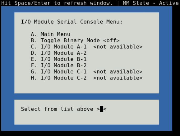
Figure 5 - I/O module console menu
To end a non-binary session, the exit sequence is “Ctrl-\”.
To end a binary session requires an extra step. The extra step is to login to the Chassis Manager’s web interface and go to Home > Troubleshoot > Terminate Serial Connection.
Server serial console
Choosing option (C) from the Main menu takes you to the Sled Host Serial Console menu (Figure-6). The menu shows you the available server host in a sled present in the chassis.
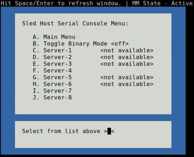
Figure 6 - Sled host serial menu
Prior to selecting a server sled, you will have the option to toggle the connection mode to either “binary” or non-binary” using option (B) from the menu. In “binary” mode, the terminal control characters from the client application are passed through the serial session.
Upon selection of a server sled, you will get access to the serial command line interface of the operating system running on the sled.
To end a non-binary session, the exit sequence is “Ctrl-\”. This exit sequence can be configured from the sled’s iDRAC UI.
To end a binary session requires an extra step. The extra step is to login to the Chassis Manager’s web interface and go to Home > Troubleshoot > Terminate Serial Connection.
Server management firmware console
Choosing option (D) from the Main menu takes you to the iDRAC Serial Console menu (Figure-7). The menu shows you the available iDRAC present in the chassis. iDRAC is the systems management firmware for a compute sled.
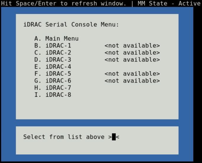
Figure 7- iDRAC console menu

Direct from Development – PowerEdge MX7000 LED Device Status
Thu, 12 Nov 2020 19:10:27 -0000
|Read Time: 0 minutes
Summary
The MX7000 chassis and modular devices in a MX7000 chassis are equipped with multi- purpose LEDs which can indicate the current health state of the device, provide identification or implement device specific features.
This whitepaper intends to provide a single point of comprehensive status information for LED behaviors on PowerEdge MX7000.
Users want to be able to look at the chassis and deduce its current health state when physically in front of the chassis. Most of the components that are present in the MX7000 chassis are able to display their current health state via LEDs.
Users also want to be able to accurately identify components in a chassis. A useful feature to do this is the Identify function that can be activated from the front panel, or remotely via the OpenManage Enterprise Modular GUI. This can be a very useful feature when you are managing a multi- chassis setup and want to remotely identify a particular device in the pool.
Some devices also implement their own specific LED behavior, for example PowerEdge MX5016s implement an LED feature that indicates mapping state. This document will cover these features.
Management Module LED Behavior
The Management Module (MM) is located at the rear of the chassis (Figure 1) and contains two LEDs: Power LED (Green only) and Status LED/Button (Blue or Amber).
Status LED/Button (Blue or Amber) is on the left and the Power LED (Green only) is on the right as shown by red highlights.
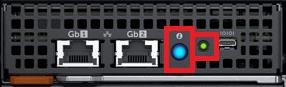
Figure 1: Management Module
The Power and Status LED (color is dependent on status) states are as follows:
Healthy Chassis
MM State | Power LED State | Status LED State |
Active | LED ON (Green) | LED ON (Blue-solid) |
Standby | LED ON (Green) | LED OFF |
Identify (Active) | LED ON (Green) | LED ON (Blue-blinking) |
Faulted Chassis
MM State | Power LED State | Status LED State |
Active | LED ON (Green) | LED ON (Amber-blinking) |
Identify (Active) | LED ON (Green) | LED ON (Blue-blinking) |
(Note: Only active MM will reflect faulted chassis state and provide identification functionality.)
Management Module Hardware Failure
Issue | Power LED State | Status LED State |
MM unable to power on | LED OFF | LED OFF |
MM unable to boot up | LED OFF | LED ON (Amber-solid) |
The Status LED/Button on the rear of the chassis changes to AMBER when any of the Front Panel iconic indicators shows AMBER. When the chassis/MM is in Identify State, the combo Status LED/Button shall always blink BLUE and override any other Status LED state.
IO Module LED Behavior
I/O Modules (IOMs) are inserted in the rear of the chassis and support a two-stacked arrangement of LEDS: Top = AMBER/GREEN, Bottom = BLUE.
Figure 2a – Typical Fab A/B IO Module: Power/Status LED on the top and Identification LED on bottom as shown by red highlights.

Figure 2b – Typical Fab C IO Module: Power/Status LED on the top and Identification LED on bottom as shown by red highlights.
The LEDs support the following functions:
IOM Health | Power/Status LED State | Identification LED State |
Healthy | LED ON (Green) | - |
Faulted | LED ON (Amber) | - |
Identify | - | LED ON (Blue-blinking) |
The green LED behavior can be overridden to indicate fabric mismatch. In case there is a fabric mismatch, green LED will blink for 2.5 seconds and then stay lit.
Sled LED Behavior
The Sleds are inserted in the front of the chassis and contain an LED for Power/Status/Identification via Blue or Amber colors.
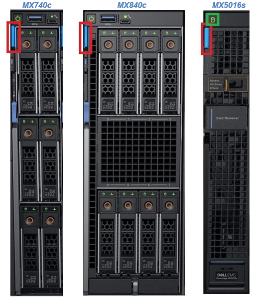
Figure 3: Current PowerEdge MX Sled Options
The Power/Status/Identification LED is on the top left highlighted in red.
The Power/Status/Identification (color is dependent on status) LED states for a sled device will be as follows:
Chassis manager firmware console
Sled Health | Power/Status/Identification LED State |
Off | LED_OFF |
Healthy | LED ON (Blue) |
Errors exist (System on/off) | LED ON (Amber-blinking) |
Identify | LED ON (Blue-blinking) |
Failsafe | LED ON (Amber-solid) |
For PowerEdge MX5016s (Figure 3), a cylindrical LED is also available marked with green highlight in the figure. Its behavior is as follows:
Mapping state | Cylinder LED on PowerEdge MX5016s |
Mapped to Compute that is powered ON | LED ON (Blinking) |
Unmapped | LED OFF |
All mapped compute sleds are off | LED OFF |
NOTE: It is unsafe to remove the PowerEdge MX5016s any time the LED is Blinking, as it is has active mappings to compute sleds that are powered on. To remove the PowerEdge MX5016s, either unmap storage from all compute sleds, or power down all compute sleds that are using this storage. See the User Guide for more information.
PSU LED Behavior
The Power Supply Units (PSUs) are inserted in the front of the chassis and utilize four LEDs: 3 on the front (figure below, left) and 1 in the back (figure below, right).

Figure 4 - Front and Rear PSU LEDs
The PSU LED states are as follows:
PSU State | Health LED (Front) | AC Present (Front) | DC Present (Front) | AC Present (Rear) |
Healthy | LED ON (Green) | LED ON | LED ON | LED ON |
Faulted | LED ON (Amber) | - | - | - |
On the front of the PSU, if the AC Present LED is illuminated, then AC is detected and within tolerance. If the DC Present LED is illuminated, then the PSU is supplying DC to the chassis. The AC Present LED on the rear of the chassis, when illuminated, indicates that AC is detected.
FAN LED Behavior
The Fans are inserted in the front and the back of the chassis (Figure 8) and contain one LED: Power/Status LED (Green or Amber).
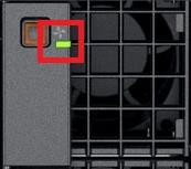
Figure 6 – Front Fans Power/Status LED
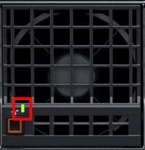
Figure 7 – Rear Fans Power/Status LED
The Power/Status/Identification (color is dependent on status) LED states will be as follows:
Fan Health | Power/Status LED State |
Off | LED_OFF |
Healthy | LED ON (Green) |
Fault | LED ON (Amber-blinking) |
Firmware Update in Progress | LED ON (Green-blinking) |
Conclusion: A thorough understanding of the physical LED status can ensure efficient health status and provide feedback for timely troubleshooting. The PowerEdge MX management module, compute sleds, storage sleds, IO Modules, power supply, and fans, each have LED state indicators that deliver identification on specific features.