
Blogs
Blog posts related to Dell Technologies PowerEdge MX products

Direct from Development – PowerEdge MX7000 At the Box Serial Access
Thu, 12 Nov 2020 19:26:21 -0000
|Read Time: 0 minutes
Summary
PowerEdge MX7000 comes with a Management Module that provides chassis management. This technical white paper describes the step by step “at- the-box” serial access feature of the chassis management firmware. A typical use of the serial access feature is for troubleshooting purpose when remote access to the management firmware is not available.
Preparation
What you need?
To prepare for serial access, you need the correct cable for connection. You will need a “micro-USB to USB” cable (Figure-1) long enough to connect your client system to the micro-USB port in the Management Module.
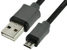
Figure 1 USB to Micro USB Cable
Where to connect?
The micro-USB port (Figure-2) for serial access is in the Management Module located at the rear of the chassis. If you see two Management Modules, look for the module that has the LED under “i” lit.
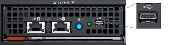
Figure 2 - Micro USB port to connect to
What you need in the client?
You can use any serial terminal client application of your choice, such as Tera Term or PuTTY.
Windows Client Host
If your client host system is running Windows, the default serial device driver should work. Open the Device Manager (type “devmgmt.msc” from command line) to determine which COM port Windows has created for your serial connection.
If Windows is not able to see the serial COM port or it is present but you are not able to connect, you may have to manually install the device driver. You can get this driver from a 3rd party vendor. Search for “cypress semiconductor usb serial driver download”. Look for the driver download link. After the manual driver installation, you should see the COM port for your connection (example in Figure-3).
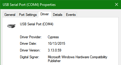
Figure 3 – 3rd party serial device driver in Windows
Linux Client Host
If your client host system is running Linux, the device driver to connect to the serial interface should already be installed. There is an extra step however that is required to correctly recognize the Management Module serial device.
The USB serial device is recognized by Linux as a “Thermometer” device and loads the cytherm kernel module. The following steps help to correctly recognize the Management Module serial device.
First, add this entry “blacklist cytherm” to the file “/etc/modprobe.d/blacklist.conf”. This will prevent loading the incorrect driver.
Next, connect the serial cable to the host system. If you have already connected the serial cable, you will need to unload the incorrect driver with the command “sudo rmmod cytherm”. Then re-connect the serial cable to the host system.
If you see “/dev/ttyACM0” then you are ready to connect. The “0” means it is the first serial device discovered.
Serial Console
Serial Console Menu
When a serial connection is established to the Management Module, the serial client application will be presented with the serial console’s main menu (Figure-4). It is populated with the available components to which serial connection can be made. On the upper right corner of the menu, it shows which Management Module you are connected to (the Active or the Standby). When you are finished, you may simply disconnect the cable and exit the serial client application.
The following sections describe each selection in the Main menu.
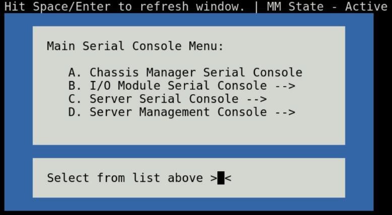
Figure 4 - Main menu
Chassis manager firmware console
Choosing option (A) from the Main menu takes you to the Chassis Manager firmware console. A serial session will open and a login prompt is displayed.
On successful login, you will have access to the Chassis Manager’s firmware racadm interface. To end the session, the exit sequence is “Ctrl-A Ctrl-X”. If using minicom in Linux, the exit sequence is “Ctrl-A Ctrl-A Ctrl-X”. Upon exit, you will see the Main menu.
I/O module firmware console
Choosing option (B) from the Main menu takes you to the I/O Module Console menu (Figure-5). The menu shows you the available I/O modules that support the serial interface.
Prior to selecting an I/O module, you will have the option to toggle the connection mode to either “binary” or non-binary” using option (B) from the menu. In “binary” mode, the terminal control characters from the client application are passed through the serial session.
Upon selection of an I/O module, a serial session will open and a login prompt is displayed. On successful login, you will have access to the I/O module firmware command line.
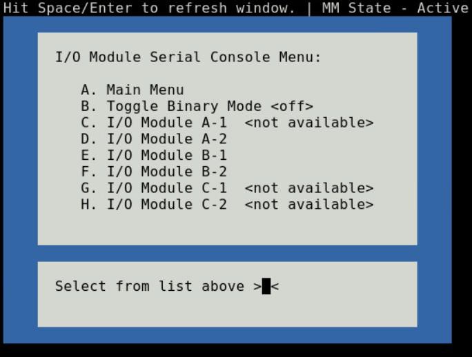
Figure 5 - I/O module console menu
To end a non-binary session, the exit sequence is “Ctrl-\”.
To end a binary session requires an extra step. The extra step is to login to the Chassis Manager’s web interface and go to Home > Troubleshoot > Terminate Serial Connection.
Server serial console
Choosing option (C) from the Main menu takes you to the Sled Host Serial Console menu (Figure-6). The menu shows you the available server host in a sled present in the chassis.
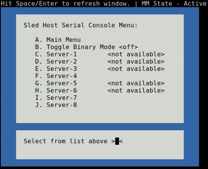
Figure 6 - Sled host serial menu
Prior to selecting a server sled, you will have the option to toggle the connection mode to either “binary” or non-binary” using option (B) from the menu. In “binary” mode, the terminal control characters from the client application are passed through the serial session.
Upon selection of a server sled, you will get access to the serial command line interface of the operating system running on the sled.
To end a non-binary session, the exit sequence is “Ctrl-\”. This exit sequence can be configured from the sled’s iDRAC UI.
To end a binary session requires an extra step. The extra step is to login to the Chassis Manager’s web interface and go to Home > Troubleshoot > Terminate Serial Connection.
Server management firmware console
Choosing option (D) from the Main menu takes you to the iDRAC Serial Console menu (Figure-7). The menu shows you the available iDRAC present in the chassis. iDRAC is the systems management firmware for a compute sled.
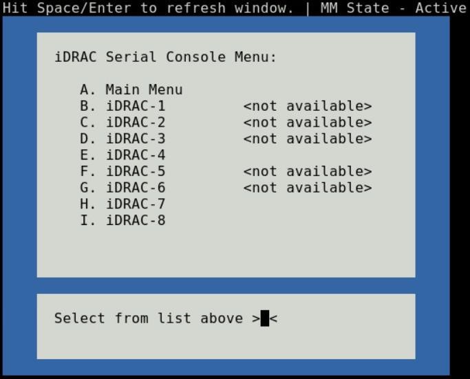
Figure 7- iDRAC console menu

Direct from Development – PowerEdge MX7000 LED Device Status
Thu, 12 Nov 2020 19:10:27 -0000
|Read Time: 0 minutes
Summary
The MX7000 chassis and modular devices in a MX7000 chassis are equipped with multi- purpose LEDs which can indicate the current health state of the device, provide identification or implement device specific features.
This whitepaper intends to provide a single point of comprehensive status information for LED behaviors on PowerEdge MX7000.
Users want to be able to look at the chassis and deduce its current health state when physically in front of the chassis. Most of the components that are present in the MX7000 chassis are able to display their current health state via LEDs.
Users also want to be able to accurately identify components in a chassis. A useful feature to do this is the Identify function that can be activated from the front panel, or remotely via the OpenManage Enterprise Modular GUI. This can be a very useful feature when you are managing a multi- chassis setup and want to remotely identify a particular device in the pool.
Some devices also implement their own specific LED behavior, for example PowerEdge MX5016s implement an LED feature that indicates mapping state. This document will cover these features.
Management Module LED Behavior
The Management Module (MM) is located at the rear of the chassis (Figure 1) and contains two LEDs: Power LED (Green only) and Status LED/Button (Blue or Amber).
Status LED/Button (Blue or Amber) is on the left and the Power LED (Green only) is on the right as shown by red highlights.
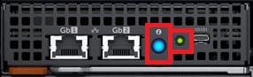
Figure 1: Management Module
The Power and Status LED (color is dependent on status) states are as follows:
Healthy Chassis
MM State | Power LED State | Status LED State |
Active | LED ON (Green) | LED ON (Blue-solid) |
Standby | LED ON (Green) | LED OFF |
Identify (Active) | LED ON (Green) | LED ON (Blue-blinking) |
Faulted Chassis
MM State | Power LED State | Status LED State |
Active | LED ON (Green) | LED ON (Amber-blinking) |
Identify (Active) | LED ON (Green) | LED ON (Blue-blinking) |
(Note: Only active MM will reflect faulted chassis state and provide identification functionality.)
Management Module Hardware Failure
Issue | Power LED State | Status LED State |
MM unable to power on | LED OFF | LED OFF |
MM unable to boot up | LED OFF | LED ON (Amber-solid) |
The Status LED/Button on the rear of the chassis changes to AMBER when any of the Front Panel iconic indicators shows AMBER. When the chassis/MM is in Identify State, the combo Status LED/Button shall always blink BLUE and override any other Status LED state.
IO Module LED Behavior
I/O Modules (IOMs) are inserted in the rear of the chassis and support a two-stacked arrangement of LEDS: Top = AMBER/GREEN, Bottom = BLUE.
Figure 2a – Typical Fab A/B IO Module: Power/Status LED on the top and Identification LED on bottom as shown by red highlights.

Figure 2b – Typical Fab C IO Module: Power/Status LED on the top and Identification LED on bottom as shown by red highlights.
The LEDs support the following functions:
IOM Health | Power/Status LED State | Identification LED State |
Healthy | LED ON (Green) | - |
Faulted | LED ON (Amber) | - |
Identify | - | LED ON (Blue-blinking) |
The green LED behavior can be overridden to indicate fabric mismatch. In case there is a fabric mismatch, green LED will blink for 2.5 seconds and then stay lit.
Sled LED Behavior
The Sleds are inserted in the front of the chassis and contain an LED for Power/Status/Identification via Blue or Amber colors.
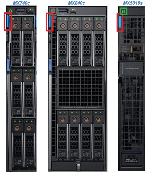
Figure 3: Current PowerEdge MX Sled Options
The Power/Status/Identification LED is on the top left highlighted in red.
The Power/Status/Identification (color is dependent on status) LED states for a sled device will be as follows:
Chassis manager firmware console
Sled Health | Power/Status/Identification LED State |
Off | LED_OFF |
Healthy | LED ON (Blue) |
Errors exist (System on/off) | LED ON (Amber-blinking) |
Identify | LED ON (Blue-blinking) |
Failsafe | LED ON (Amber-solid) |
For PowerEdge MX5016s (Figure 3), a cylindrical LED is also available marked with green highlight in the figure. Its behavior is as follows:
Mapping state | Cylinder LED on PowerEdge MX5016s |
Mapped to Compute that is powered ON | LED ON (Blinking) |
Unmapped | LED OFF |
All mapped compute sleds are off | LED OFF |
NOTE: It is unsafe to remove the PowerEdge MX5016s any time the LED is Blinking, as it is has active mappings to compute sleds that are powered on. To remove the PowerEdge MX5016s, either unmap storage from all compute sleds, or power down all compute sleds that are using this storage. See the User Guide for more information.
PSU LED Behavior
The Power Supply Units (PSUs) are inserted in the front of the chassis and utilize four LEDs: 3 on the front (figure below, left) and 1 in the back (figure below, right).

Figure 4 - Front and Rear PSU LEDs
The PSU LED states are as follows:
PSU State | Health LED (Front) | AC Present (Front) | DC Present (Front) | AC Present (Rear) |
Healthy | LED ON (Green) | LED ON | LED ON | LED ON |
Faulted | LED ON (Amber) | - | - | - |
On the front of the PSU, if the AC Present LED is illuminated, then AC is detected and within tolerance. If the DC Present LED is illuminated, then the PSU is supplying DC to the chassis. The AC Present LED on the rear of the chassis, when illuminated, indicates that AC is detected.
FAN LED Behavior
The Fans are inserted in the front and the back of the chassis (Figure 8) and contain one LED: Power/Status LED (Green or Amber).
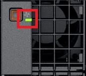
Figure 6 – Front Fans Power/Status LED
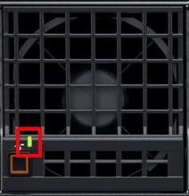
Figure 7 – Rear Fans Power/Status LED
The Power/Status/Identification (color is dependent on status) LED states will be as follows:
Fan Health | Power/Status LED State |
Off | LED_OFF |
Healthy | LED ON (Green) |
Fault | LED ON (Amber-blinking) |
Firmware Update in Progress | LED ON (Green-blinking) |
Conclusion: A thorough understanding of the physical LED status can ensure efficient health status and provide feedback for timely troubleshooting. The PowerEdge MX management module, compute sleds, storage sleds, IO Modules, power supply, and fans, each have LED state indicators that deliver identification on specific features.

Direct from Development – PowerEdge MX7000 LED Control Panel
Thu, 12 Nov 2020 18:43:08 -0000
|Read Time: 0 minutes
Summary
This blog describes the features and capabilities provided by the control panels, specifically the LED Options. There are two other left control panel options discussed in separate blogs.
MX7000 Chassis and Front Control Panels
PowerEdge MX7000 chassis comes with a left and right control panel that contains buttons, LEDs and ports that provide chassis power status, chassis power control, chassis component health status, system identify and chassis management connectivity.
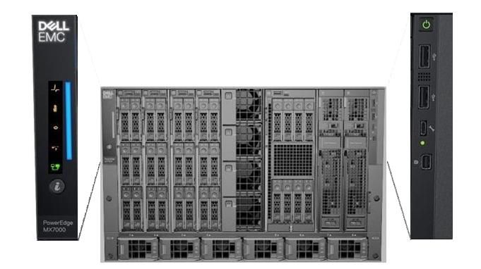
Figure 1 – PowerEdge MX7000 front control panels
Right Control Panel
Looking in front of the chassis, the right control panel contains the following button and ports.
- The chassis power button
- USB type-A port 1
- USB type-A port 2
- Micro-USB port
- Mini DisplayPort
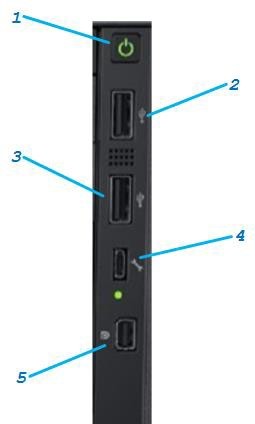
1. Power Button
The power button on the right control panel provides chassis power status and chassis power control. When the LED of the power button is lit green, the chassis power state is ON. If not lit, the state is OFF.
Turning chassis power ON
If the chassis power state is OFF, pressing the power button will cause the chassis power to turn ON.
Turning chassis power OFF
If the chassis power state is ON, pressing the power button and releasing it after a second will cause the chassis power to turn OFF “gracefully”. If there are no sleds present or there are sleds present but none are in the power on state, then the chassis power is turned OFF immediately. Otherwise, there are sleds present and powered on:
- Chassis power will turn OFF only when all sleds power state is off within one minute.
- A sled power turns off if the running operating system shuts down into completion.
- Otherwise, the sled power remains ON and the chassis power remains ON.
If the chassis power state is ON, pressing the power button and holding it pressed for at least 6 seconds before releasing will cause the chassis power to turn OFF “ungracefully”. The power is turned off from all chassis infrastructure include sleds that are present and powered on.
NOTE: Take caution when doing an “ungraceful” power OFF. Data that is actively being written to any storage device used within the chassis at the time of “ungraceful” power off may become corrupted.
Chassis power state transition is described in further detail in a separate whitepaper.
2. & 3. USB type-A port
There are two standard USB type-A ports present on the Right control panel. These ports are used for connecting keyboard & mouse used for the at-the-box KVM connectivity feature. The KVM feature is discussed in further detail in a separate whitepaper.
4. Micro-USB port
The micro-USB port is used to connect to the Chassis Management firmware. This port is currently not implemented and will be implemented in future release of the Management firmware.
5. Mini DisplayPort
The mini DisplayPort is used for connecting video used for the at-the-box KVM connectivity feature. The KVM feature is discussed in further detail in a separate whitepaper.
Left Control Panel Status - LED Version
Looking in front of the chassis, the left control panel contains the following button and LEDs.
- Chassis health status LED
- Ambient temperature health status LED
- Rear I/O module health status LED
- Fan health status LED
- Stacking state LED
- Status LED
- System identify button
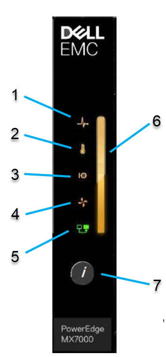
Figure 3 - Left control panel (Status LED Version)
1. Chassis Health Status LED
The Chassis health status LED blinks AMBER color when the Chassis health state is degraded; otherwise the LED is OFF.
2. Ambient Temperature Health Status
The ambient temperature health status LED blinks AMBER color when a thermal fault exists for the chassis; otherwise the LED is OFF. A thermal fault may occur with excessive chassis ambient temperature, IOM thermal status, power supply thermal status and fan status.
3. Rear I/O Module Health Status LED
The rear I’O module health status LED blinks AMBER color when an I/O module fault exists; otherwise the LED is OFF
4. Fan Health Status LED
The fan health status LED Blinks AMBER Color when there is a failure or warning associated to the front and rear fans; otherwise the LED is OFF.
5. Stacking State LED
The stacking state LED is currently not implemented and will be activated upon future release of the Management firmware
6. Status LED
The Status LED is used to present the overall health state of the chassis and also used for Chassis system identify.
- When the overall health status is not healthy (a fault exist), Status LED blinks AMBER.
- When system identify is enabled for the Chassis, Status LED blinks BLUE.
- Otherwise, the overall health status is healthy and Status LED is lit solid BLUE.
7. System Identify Button
The System identify button is used to blink/un-blink the chassis and sled status LED. The blink color is BLUE. System identify feature is described in detail in a separate technical whitepaper.
Left Control Panel Status - LCD Version
The left control panel configuration can be the graphical LCD panel. The LCD panel is a graphical touch screen panel that provides enhanced at-the-box control panel capability. The LCD feature is described in further detail in a separate technical whitepaper.

Direct from Development - PowerEdge MX7000 Chassis Management Networking Cabling
Thu, 12 Nov 2020 18:48:02 -0000
|Read Time: 0 minutes
Summary
This blog describes the new and improved features of the MX7000 chassis management network, provide recommended network cabling diagrams, and show the fault tolerant capabilities of the new network design in the new Dell EMC 14G MX7000 chassis.
The MX7000 chassis features dual redundant management modules, with each management module featuring two management network ports, for a total of 4 management network ports on the chassis.
The management network is meant to provide network connections for chassis management that is separate from the customer data network. There are several new and improved design points for this network compared to previous generation chassis that significantly impact how these new chassis should be cabled and managed.
New Feature: Automatic Uplink Detection
The first thing to notice about the MX7000 network physical chassis is labelling: as opposed to the older M1000e chassis, you will notice that the management ports are not labelled “STK” (stacking) or GB (uplink), but rather just GB 1 and GB 2. Because of the new automatic detection features in MX7000, you can use any port for stacking and/or uplink, and the management module will automatically detect each port to determine if it is a stacking or uplink port.
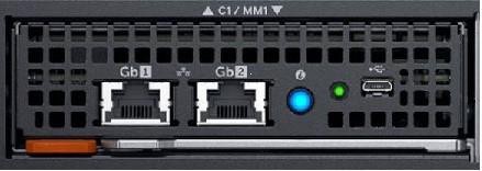
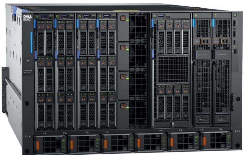
Figure 1 – MX7000 Management Module
New Feature: Network Loop Prevention
When cabling chassis in a stack, you will notice is what appear to be connections forming network loops and redundant connections between the chassis. The management modules will automatically detect redundant ports between chassis and will block packets automatically to prevent network loops from forming.
There are a couple points worth noting about this feature. First, when you stack chassis and cable them together, only one uplink will ever forward traffic out of the stack. The recommended cabling configuration has two links from chassis to the top of rack switch. However, if you have the recommended redundant connections out of the stack, all of the “extra” redundant connections will be in a “blocking” state, i.e. Link-UP, but not forwarding network traffic. If the system detects a link failure of the active link, the chassis will automatically fail over to the redundant links.
Cabling an Individual Chassis
When cabling an individual chassis, connect one network cable from each management module to the data center top of rack switch. Ensure that both ports on the top of rack switch are enabled and on the same network and VLAN.
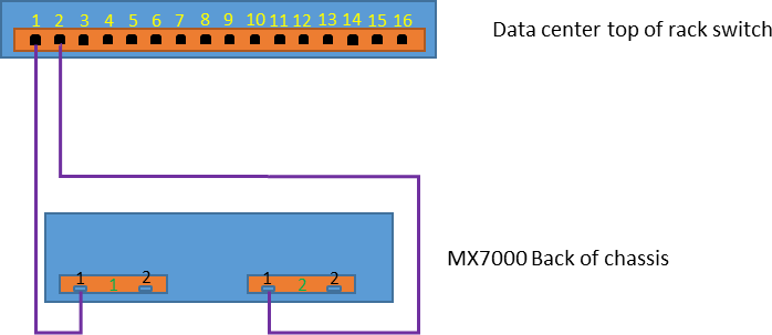
Figure 2 – Schematic representation of single chassis connection
This configuration provides redundant network access to the chassis, protecting against link failure or management module failure. You can cable the redundant connections to the same top of rack switch or to two redundant switches, just be sure to configure both connections the same and have them on the same network and VLAN.
As mentioned above, there is no need to prefer either GB 1 or GB 2 for these connections.
Cabling an Individual Chassis
With the automatic uplink detection and network loop prevention, it is possible to connect multiple chassis one to the other with cables to save port usage in the data center switches and still access each chassis over the network. When multiple chassis are cabled in this manner it is known as a “stack”.
Note: While the automatic uplink detect and network loop prevention allow for chassis to be interconnected without network issues, stacked chassis are not automatically part of a management group.
See the MX7000 Multi Chassis Management feature for group management. This feature (not covered in this blog) lets you manage multiple chassis through one management module, and requires the network stacking arrangement described here.
Recommended Topology for Multiple Chassis
While the auto sensing loop prevention algorithms allow for virtually any topology and provides access to all components in the stack of chassis, there are optimum topologies for connecting a group of chassis. These topologies provide redundant connections into the stack and optimize network down time for firmware updates and possible faults. The cabling diagram shown will protect against any single point of failure in the entire stack. With this configuration you can survive the followingfailures and retain full management network access to all nodes in the stack:
- Any single network cable failure
- Any single management module failure
- Power loss to any single chassis in the stack
It is important to note that these are the minimum failures that we have designed protection for. It is possible to have more failures than the above and still have full functionality, but it would depend heavily on where those failures occurred.
Here is an example topology for a 12 Chassis Dual MM chassis stack, connected to a top of rack switch at ports 1 and 4:
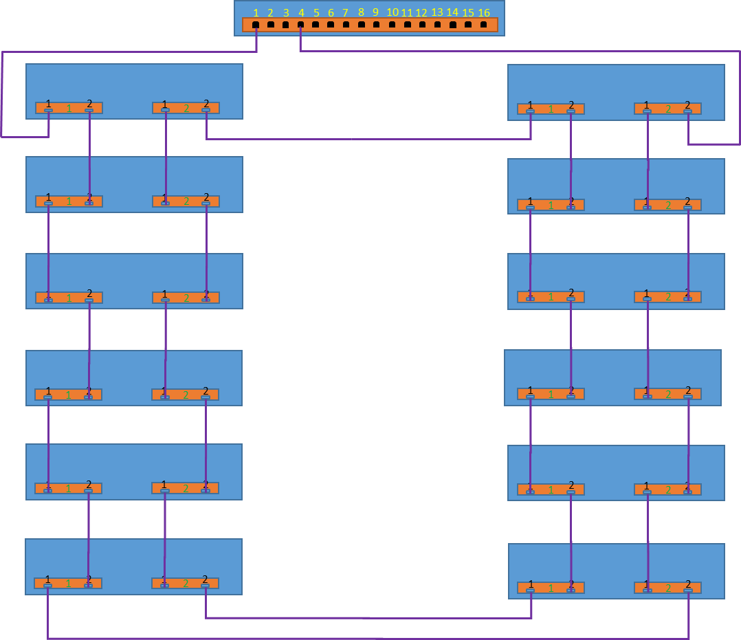 Figure 3 – Schematic representation of multiple chassis connections
For consistent access to all chassis and their components from a management network, it is important that both ports 1 and 4 are connected to the same layer 3 network. A very common misconfiguration that we have seen is accidentally connecting the two redundant uplink ports to different VLANs. If the chassis are connected to different VLANS, when the primary link fails, you will lose access to your management network.
As can be seen, all chassis are connected with their neighbor chassis with redundant connections. The two chassis that are connected to the top of rack switch are connected to each other, providing a redundant connected path. This redundant path is important to allow the stack to survive power loss to a full chassis in the middle of the stack.
While the management module contains a concept of “Active” versus “Passive” roles, networking for the chassis’ is independent of these roles.
The networking algorithm uses Spanning Tree Protocol to determine a network path to each and every component in the Fab-D stack. This may include forwarding paths through “Passive” MM modules. It is important to note that Spanning Tree is *not* enabled on any uplink ports to top of rack switches. Spanning Tree is automatically configured between MX7000 chassis, and is not ever configured on links that are not MX7000 chassis.
One important thing to be aware of are network disruptions caused by cabling or link changes in the stack. When links change, for example if a cable is pulled or added, the network may go down for approximately 30 seconds to re-compute the network topology. This affects all chassis in the stack. One thing you will notice is that every time cabling or link state changes in the stack, all iDRACs and management modules in the stack will reconfigure their network. If the components are configured for DHCP, you will see them refresh their IP addresses.
The above is true for both DHCPv4 and DHCPv6.
Reserved VLANS
To implement the features for auto uplink detection and network loop prevention, the MX7000 chassis internally use VLAN in the series 4000 through 4020. This series is reserved by the management module and chassis components and cannot be used for access through the uplink connection.
All other possible VLANS are available for use and VLAN tagged packets will forward through the stacked chassis.
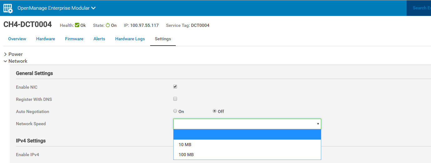
MX7000 External Port Settings
For all chassis in a stack, it is important that all chassis external port settings are set to the same configuration.
Each management module in the MX7000 chassis has two RJ-45 Ethernet ports labeled “gb1” and “gb2”. Each port is configured to be Auto MDI-X, which typically eliminates the need for an Ethernet crossover cable when connecting any MX7000 port to another chassis or top of rack switch. This is a non-configurable setting.
Some port settings, such as speed and auto-negotiation can be configured through the management GUI. All ports on the chassis will configured with the selected values. When actively changing this chassis setting, there will be a delay in access while the settings are applied.
Note: If non-auto negotiate settings are selected, the switch that the chassis is connected with MUST be also changed to the same speed and duplex values.
Additionally, Auto MDI-X may not function properly when auto- negotiate is off, resulting in a link down state.
In a dual management module chassis, all four external gb1 and gb2 ports are set to the same settings.
Direct from Development – PowerEdge MX7000 Reset to Default
Thu, 12 Nov 2020 18:50:43 -0000
|Read Time: 0 minutes
Summary
This blog discusses the “Reset to Default” feature found in Dell’s new PowerEdge MX7000 chassis, Also outlined are the front panel configuration storage options.
In this blog, we will outline all of the settings that are reset when a user performs a reset to defaults on the MX7000 chassis. Additionally, we describe the settings that are stored in the front panel so that users can understand what settings will need to be re-applied when management modules are replaced.
Reset to Default
Users can initiate a reset to defaults operation from either the racadm CLI utility, or via a REST API call to the management module. See below for the details on each of these.
During the reset configuration operation, the management module reboots, wipes out applicable configuration and restores them to the factory default values. Detailed information of reset configuration success/failures are logged in hardware logs (See CMC8731/CMC8732 in the Dell Message Registry). After a reset operation, you will always see the reset to defaults logged.
The Dell EMC MX7000 chassis supports a “Multi Chassis Management” (MCM) feature, which allows a stack of chassis that have been physically cabled together to be managed through a single management module.
Lead Chassis: If a chassis is lead chassis of a MCM group, then you must dissolve the MCM group before performing reset to default. The command will fail if you attempt to reset to defaults in an MCM Lead setup and an error message will return. Error Message: “Reset to defaults is not supported on a lead chassis in the MCM group.”
Member Chassis: If a chassis is member chassis of a MCM group, reset configuration is supported. However, chassis will be removed from the MCM group after the operation and become a standalone chassis.
Standalone Chassis: Reset configuration is fully supported for standalone chassis.

Resettable Management Module Configuration
This is a comprehensive list of configuration items which are impacted when a reset to default function is performed
- User Configuration
- Reset root password to factory shipped default password
- Identity Configuration
- Reset chassis to default brand
- Web SSL Certificate
- Re-generate web SSL certificate and key
- Firewall configuration
- Reset firewall configuration to default
- SNMP and SSH related configurations
- Network Configuration Settings
- Reset IPv4, IPv6, DNS, VLAN settings to defaults
- Other User Configurable Settings
- Reset below settings to defaults
- Chassis Power Settings
- Chassis Settings – Asset Tag, Chassis Name
- Chassis Topology Settings
- KVM Setting - Enable
- LCD Settings
- Network Switch Settings
- Quick Sync Settings
- Security Settings – Customer Certificate, Private Key
- Serial Settings
- Time Settings
- Reset below settings to defaults
Resettable Management Module Logs
- Hardware logs
- OpenManage Enterprise (OME) Modular logs
- Dumplog logs
Interfaces
To perform a reset to defaults, use one of the following interfaces:
- Redfish API
URI: api/ApplicationService/Actions/ApplicationService.ResetApplication JSON Payload:
{           "ResetType":"<ResetType value>"                                                            }
Supported ResetType values:
- RESET_CONFIG: Reset resettable management module configuration mentioned above
- RESET_ALL: Reset resettable management module configuration and logs mentioned above (RESET_ALL = RESET_CONFIG + logs)
- Racadm
The CLI racadm command is equivalent to Redfish API ResetType of RESET_CONFIG.
racadm racresetcfgLocked Management Module Configurations
Reset configuration with types of RESET_CONFIG and RESET_ALL will not reset these management module configuration settings:
- Chassis MAC Addresses
- Chassis Service Tag
- Factory Shipped Default Password
- Identity Certificates
Management Module Configuration Persistence
Management module configuration data persist through system boots and failovers. Some configuration settings persist through management module card replacement because they are stored in nonvolatile flash memory located in chassis right control panel. If the right control panel is replaced, the current management module configuration is lost and the system will assume the management module configuration in the new right control panel. If the new right control panel has not been configured or has been performed reset to defaults, new management module configuration will use the default factory values.
Below configurations persist through management module card replacement:
- Root Password
- Branding ID Module
- Network Configuration Settings (as listed above)
- Other User Configurable Settings (as listed above)
- Hardware Logs
- Chassis MAC Addresses
- Chassis Service Tag
- Factory Shipped Default Password
Conclusion
Periodically it might be necessary to reset a chassis and in this blog we discussed the methods and interfaces to perform reset to factory defaults, along with a listing of the settings that are reset, and settings that are not impacted. The retention of some persistent storage of the critical chassis information on the chassis right control panel, and which settings are retained in case of management card replacement mean that they reduce risk and increase chassis availability.

Direct from Development – PowerEdge MX Secure Chassis Management
Thu, 12 Nov 2020 18:53:31 -0000
|Read Time: 0 minutes
Summary
This blog describes the innovative new security features that are built-into the new Dell EMC MX7000 chassis.
We will cover the secure boot features built into the Management Modules and iDRAC, the ground-up security design incorporating SELinux and least-privilege processes, and our new mechanisms that ensure the security of all management traffic inside the chassis by authenticating and authorizing every component in the chassis, as well as the encryption for all internal management network traffic.
The intent of all of this work is to make a more secure system for customers, one that customers can trust and rely on, and is secured using the best available security techniques against hacking.
Secure Boot
The first principle of security of an embedded management controller is answering the question of what code is running on that management controller. Is the code running on the management controller authentic code from Dell, or has the device been attacked or compromised in any way? The way that we have comprehensively addressed this question for the MX7000 Management Module is our secure boot and chain of trust. Using these techniques, explained below, we can ensure that the Management Module is running unmodified code that has been authenticated by Dell, and that there is no way an attacker has tampered with or replaced any code, either through a supply-chain attack, or through any kind of online attack.

The technique that we use to secure the Management Module is based on the “Chain of Trust” concept. In this concept, each stage of the boot process uses digital signatures to cryptographically verify that the next stage of boot is signed properly before jumping to the next stage.
The beginning of this chain of trust starts in the factory, when the iDRACs and Management Modules that make up the MX7000 are being built. Our hardware is programed with keys, fused to the device, that allow the processor to verify the bootloader prior to starting, the bootloader in turn has its own keys to verify the verify the kernel. Once booted the Kernel runs on a read only file system, further preventing tampering. Each Management Module and iDRAC is also programmed with device unique Identity certificates, which are a public/private keypair used by the device to identify itself as authentic Dell to others. These are signed by the Dell Certificate Authority, are unique to the device and stored encrypted by the devices Hardware Root Key, described below. So each layer of the system verifies that the next is authentic and has not been modified, creating a complete chain of trust from hardware to running code.
One critical part of the secure boot process is the presence of a unique-per- machine Hardware Root Key (HRK). This symmetric encryption key is is physically fused into the microprocessor during manufacturing. This HRK is never visible or extractable from the OS or applications running on the management controller, however, applications can make cryptographic requests to the hardware crypto accelerator to encrypt or decrypt information using this key. More importantly to our security design, access to this HRK can be disabled at runtime in a manner that cannot be re-enabled without a power cycle. If at any point in the boot process the system detects that it is running non-Dell code, the HRK is disabled. Why this is important will be explained a little bit later.
SELinux and Least Privilege
After you have ensured that the physical flash is secure and running clean, signed Dell EMC firmware images, the next step is to protect the system from online attacks that would allow an attacker to gain access to a running system through some software vulnerability. We have done this through a combination of two techniques that we have integrated into our development process. First, we have adopted SELinux for all of the management controllers in the MX7000: the Management Module as well as the IDRACs. The 1.0 version of MX7000 firmware ships with SELinux fully enabled and set to the highest level of enforcement out of the box, without any configuration requirements for customers to worry about. The second major runtime security initiative that we have delivered is “least privilege”. This security concept enforces each process to run with an individually unique, non-administrative Unix user account. The combination of these two security techniques helps to mitigate any vulnerabilities that might be found: what would formerly have been a major security hole can sometimes be mitigated down to a minor inconvenience.
This combination of SELinux and “least privilege” protects the sensitive areas of the MX7000 iDRAC and Management Modules. Only the processes associated with establishing machine to machine trust have access to the private key information on the device and access to these processes limited. With defined separation of tasks and access between the difference processes, an attacker of the MX7000 would find their ability to modify or control a system extremely limited, and accessing a remote system unlikely.
Machine to Machine Trust
So far, we’ve been building up a single system piece-by-piece in a secure manner, first by encrypting and verifying the boot process, next by ensuring that the running firmware image is protected. Next, we need to think about how we ensure that each component in the chassis can trust the other components and communicate with them in a secure manner.
As noted previously, each Management Module and iDRAC have a unique Identity certificate, signed by a Dell Certificate Authority. These certificates are a key part of the trust establishment between the various iDRAC and Management Modules inside the MX7000. Each system on startup will verify the installed certificates against the Dell EMC Root CA to assure they are valid. Certificates that are corrupted or invalid will be unable to establish machine to machine trust with other devices in the chassis.
Once assembled and powered on the MX7000 Management Modules and iDRACs will automatically start the discovery and machine to machine trust establishment process. All network communication inside the MX7000 is done over private IPv6 VLANs. The addresses in these VLAN’s are stateless and based on the router advertisement from the Enclosure controller. To locate other devices over the 2^128 IPv6 address space, individual devices use mDNS announcements to broadcast their presence. As the iDRAC and Management Modules discover each other they begin the process of establishing machine to machine trust.
A Management Module or iDRAC wishing to access resources on a discovered iDRAC or Management Module will need to prove it is an authentic Dell device to gain access. A ECIES (Elliptic Curve Integrated Encryption Scheme) using a ECDH (Elliptic Curve Diffie-Hellman) key exchange is used to pass the public portion of a “clients” certificate to the discovered “server”. The server will validate the certificate chain of the public certificate against the Dell root CA. If valid, the server will use the public key present in the certificate to form the shared symmetric key. The final piece of the puzzle is giving the server a way to validate that the client actually has access to the private key for the unique identity certificate. To do this, the server uses a technique called “proof-of-possession” that is specified in RFC 7800. The proof- of-possession verification assures the server that the client has both public and private portions of a valid Dell Identity certificate. Having fully vetted the client, the server will provide the client with a temporary JWT (Java Web Token) that the server has signed and the client can use to access the resources of the server.
Encrypting management network traffic
In previous versions of PowerEdge servers, communications between devices with a chassis was expected to be secure due to the ‘physical’ security of a private internal network. A iDRAC blade would automatically become part of the chassis group by being physically inserted into the chassis. Communications to the sled from the CMC were done over telnet, HTTP, and other unencrypted channels. The authentication between the processes on the devices was often common shared passwords or other such preprogrammed credentials. While this was an extremely fast and robust design, Dell EMC has evaluated these processes and identified security concerns, concerns that have been addressed in the MX7000.
No longer are communications made over “clear text” HTTP connections, the new Redfish interface used in the chassis is done completely over HTTPS. The encryption of the REST information prevents packet snooping by other devices on the network. Previous multitenant chassis could be compromised by a malicious user, attempting to steal information from others on the same chassis. With the encrypted HTTPS communications this is no longer possible.
HTTPS is not the only communications path updated on the MX7000, all communications between iDRACs and Management Modules inside the chassis is encrypted. Linux sockets between iDRAC and the Management Module are encrypted using ECC (Elliptic Curve Cryptography). Communications over network sockets is possible only after iDRAC and Enclosure Controller have established bidirectional machine to machine trust. Only when both sides have vetted the other, are the connections established, using the keys transferred during trust establishment. This protects data passed between the devices, preventing snooping, as well as blocking attackers from pretending to be a Dell EMC device and accessing data.
Another issue addressed in the MX7000 is the use of a common default or fixed “hidden” user accounts with passwords programmed into the firmware. A fixed username/password know to the software allowed each device to quickly access and configure others without requiring the user interaction. The pitfalls of a common shared passwords are well documented and to avoid these issues the new MX7000 chassis uses unique, short duration and stateless token authentication. Unlike the normal username and password tokens are not tied to an actual user account on a device. In the MX7000 the iDRAC can issue an admin token to the MSM for reading/changing configuration without effecting user based authentication from its GUI. The MSM does not need a ‘user’ account and the new automated machine to machine trust assures the iDRAC is talking to an authentic MSM. Since the MSM is now a trusted administrator this presents all sorts of new possibilities.
Conclusions
In this blog, we demonstrated how the PowerEdge MX solution has a robust security protocol and architecture. By implementing a secure boot process within the MX7000 we ensure that the system starts running only if the code passes integrity checks. Subsequently runtime security measures ensure that the system remains safe from malicious hacking attempts. And additionally, a validated network security measure ensures that everything in the chassis is a system running trusted code. These enhanced security measures use best-in-class tools to protect customer systems, and we believe that this new chassis represents the most secure chassis management system in the industry.

Direct from Development – PowerEdge MX Power Redundancy
Thu, 12 Nov 2020 18:38:08 -0000
|Read Time: 0 minutes
Summary
This blog discusses core details associated with the PowerEdge MX redundant power features. Specifically called out are the grid power options and associated redundancy features.
Power considerations are key to a successful kinetic infrastructure deployment and planning for sufficient power and redundancy. Discussed are the AC & DC options associated with the chassis deployment options.
Shared Power Infrastructure
MX7000 continues Dell EMC’s commitment to maximize performance-per-watt through the consolidation of servers and network switchgear into a single high- density chassis using 14th generation ultra-efficient power supplies and dynamic power-efficient fans.
A shared power infrastructure takes advantage of the aggregation of multiple servers by distributing power across the system without the wasted power margin seen with individual monolithic servers and switchgear. Shared resources allow for a common power policy across all servers in chassis.
The power distribution inside the PowerEdge MX7000 Modular Server System consists of a 3+3 redundant power supply system, located in the rear bottom of the chassis. Each power supply is rated at 3000W bringing total system redundant power is approximately 9000W in a 3+3 power supply configuration. Each power supply unit (PSU) is hot-swappable and are accessed from the front of the chassis with power cables that can stay permanently attached to the rear.
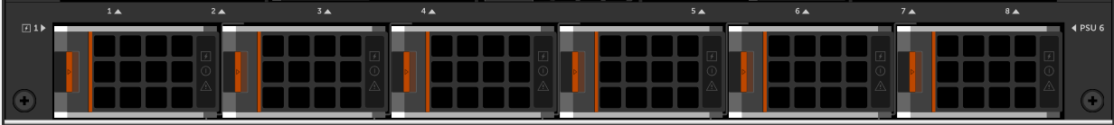
Figure 1 – PSUs Removable from the front of the chassis
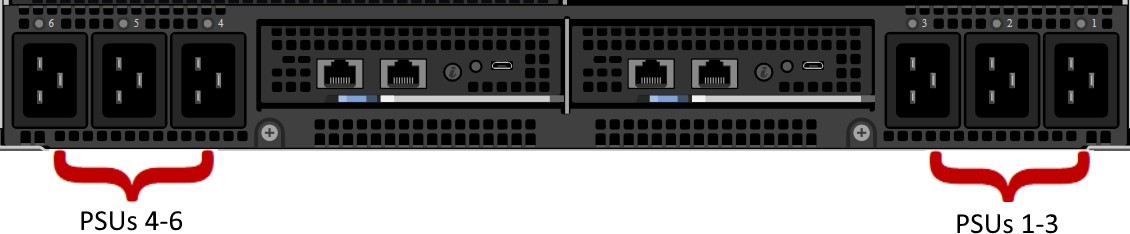
Figure 2 – AC power connected in the rear of the chassis
The chassis power supplies are on a common output bus so that, if any PSU fails, neighbor PSUs can pick up the load. Because of this, there are multiple PSU redundancy modes supported for the MX7000.
If there are two power grids feeding the data center racks, AC Grid Redundancy policy can provide the greatest protection against both AC loss or PSU failure:
- If Power Grid #1 fails, PSUs 4-6 will continue to operate from Power Grid #2
- If Power Grids #1 and #2 are operational, the system can suffer the failure of up to 3 PSUs in a 6-PSU configurations without affecting the operation of the chassis.
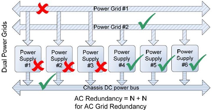
Figure 3 – AC Grid Redundancy – Loss of a power grid allows for uninterrupted operation.
Should either of these failure scenarios occur, the MX7000 will set a fault and can be configured to send notification of the issue.
Whether a single or dual AC Grid is employed, the MX7000 can be configured to support DC Redundancy. This configuration allows for 1 or more PSUs to fail yet keep the chassis fully operational.
As shown in Figure 4, the failure of one PSU will not cause failure of the chassis DC power bus. The likelihood of multiple power supplies failing at the same time is remote. If additional PSU capacity is installed (i.e. installing a fourth PSU in the bottom example of Figure 4), the chassis can suffer multiple PSU failures without affecting system operation.
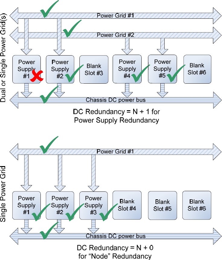
Figure 4 – DC Redundancy, 2 AC Grid or Single Grid
By default, the MX7000 is configured with no redundancy policy selected. If there is sufficient PSU capacity (i.e. extra PSUs above the capacity needed to operate the chassis), the system will continue to operate if there are any PSU failures. However, no fault will be raised.
Power Redundancy Policy Selection
Power Redundancy Policy selection can be changed via the MX7000 GUI. In the MX7000 web interface, click the Settings page. Then select the Redundancy Policy from the Redundancy Configuration section
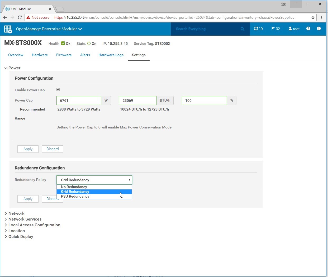
Figure 5 – Redundancy Configuration in the MX7000 Web Interface
Power Management
Shared power in modular systems take advantage of the power pool by distributing power without the waste seen in dedicated rack-mount servers and switchgear. The MX7000’s advanced power budget Inventory allows it to provide priority to powering infrastructure while guaranteeing computing resources can be used.
The Management Module and each server’s iDRAC management controller negotiates its required power, whether that be for simple power-on, AC recovery, or Wake-On-Lan. This inventory considers CPU, memory, storage, and other server I/O to provide additional margin should any power shortage occur.
Budgeting is transparent to the system administrator. The MX7000 automatically protects against using more power than is available by limiting which components can be powered on, as well as by dynamically limiting server power.
The MX7000 management module and the servers’ iDRAC modules work in concert to constantly monitor power conditions in the chassis. In the event of a power shortage, they will instantaneously limit power to servers, decreasing performance, but keeping the chassis online. Once the power shortage is corrected, servers will be allowed to return to their full performance.
Power Supply Fault Detection
The PowerEdge MX7000 logs failures of PSUs. Notifications will be sent per the configuration in the OpenManage Enterprise Modular web interface. The PSU utilizes four LEDs to help with issue identification: 3 on the front the PSU, one on the back:
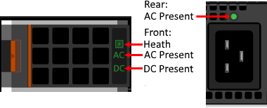
Figure 6 – PSU Fault LEDs in green
Front:
- Health – Green indicates the PSU is Healthy, Amber designates a fault
- AC Present – When illuminated, indicates that AC is detected and within tolerance.
- DC Present – When lit, shows that PSU is supplying DC to the chassis.
Rear:
AC Present – When illuminated, AC detected
Troubleshooting Tips:
- If the Rear AC Present LED fails to illuminate:
- Check to make sure the PSU in the front of the chassis is installed in the correct slot and is fully seated.
- Verify that the power cable is installed in an operating AC outlet/PDU
- If the Rear AC Present LED is illuminated but the Front AC Present LED is not:
- Verify that the AC power being provided by the utility is within tolerances.
- Check to make sure the PSU in the front of the chassis is installed in the correct slot and is fully seated.
- If the Health LED is Amber the PSU has a fault and needs to be cleared.
- Remove the PSU for a minimum of 30 seconds.
- Verify that nothing is obstructing the front outlet and the rear PSU pins are not damaged.
- Re-insert the PSU and verify that it is fully seated.
- If the Health LED blinks Amber multiple times and then turns off, PSU is indicating a capacity mismatch. Likely reasons for this are:
- PSU is connected to a different input voltage than the other PSUs (ex. 110 VAC instead of 208VAC).
- Input power power provided by the utility is not consistent or within tolerances.
- If the Health LED blinks Amber multiple times and then turns off, PSU is indicating a capacity mismatch. Likely reasons for this are:
- Re-insert the PSU and verify that it is fully seated.
Tolerances: 220VAC (single PSU runs 180V – 264VAC) or 110VAC input.

Direct from Development – PowerEdge MX and Intel QAT
Wed, 11 Nov 2020 12:36:28 -0000
|Read Time: 0 minutes
Summary
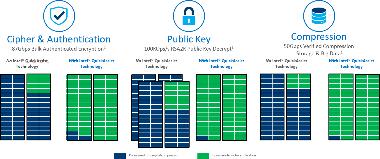
PowerEdge MX is the first Dell EMC server to offer a software licensing option to enable Intel® QuickAssist Technology. It provides a software-enabled foundation for security, authentication, and compression, and significantly increases the performance and efficiency of standard platform solutions. Intel QAT on PowerEdge MX servers offer performance across applications. That includes symmetric encryption and authentication, asymmetric encryption, digital signatures, RSA, DH, and ECC, and lossless data compression.
Encryption and Key Generation
Many users will be familiar with the “https” prefix on frequently-visited websites. Behind all of these secure websites is an implementation of TLS (transport layer security) or its predecessor SSL (secure sockets layer). Each protocol entails a “handshake” between the client and server that establishes authenticity of the server and creates a session key for encrypting the exchanged data. These Public Key Encryption (PKE) algorithms, historically performed by software, can be offloaded from the CPU into the Intel® QAT engine for providing significant performance gains for Web Server, eCommerce, VPN, Firewall or Security Load Balancer and Wan Acceleration solutions.
Data Compression and Decompression
Users of “zip” files will be familiar with the benefit of another common software function, data compression. Like cryptography, compression and decompression can be compute-intensive functions. Intel® QAT is comprised of acceleration engines for data compression as well, yielding faster performance and higher throughput for software and systems that rely on compressed data such as storage, web compression, big data, or high performance computing (HPC).
Benefit of Intel® QAT
It really boils down to the TCO, or total cost of ownership. A web server, cloud load balancer, or security gateway that can handle significantly more secure connections per second and provide high performance encrypted data throughput for reduced infrastructure cost. A storage system that uses accelerated compression to decrease the total required capacity vastly reduces storage footprint and subsequent costs. Application efficiency also reduces the thermal footprint of a datacenter or computing cluster, lowering energy costs. Improved efficiency and reduced active power for security and compression translate to reduced infrastructure.
Supported Operations
- Symmetric (Bulk) Cryptography
- Ciphers (AES, 3DES/DES, RC4, KASUMI*, ZUC, Snow 3G)
- Message digest/hash (MD5, SHA1, SHA2, SHA3) and authentication (HMAC, AES-XCBC)
Supported Operations (cont)
- Algorithm chaining (one cipher and one hash in a single operation)
- Authenticated encryption (AES-GCM, AES-CCM)
- AES-XTS
- Wireless
- KASUMI, Snow 3G and ZUC in encryption and authentication modes
- Asymmetric (Public Key) Cryptography
- Modular exponentiation for Diffie-Hellman (DH)
- RSA key generation, encryption/decryption and digital signature generation/verification
- DSA parameter generation and digital signature generation/verification
- Elliptic Curve Cryptography: ECDSA, ECDHE, Curve25519, SM2
- Compression/Decompression DEFLATE (Lempel-Ziv77) & Huffman.
Introducing Optional Software Licenses for Intel® QAT in PowerEdge MX
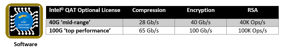
Intel® QAT has a long history with the deliveries of the 8920 model and the subsequent 8955 on PCIe cards. In the Intel® Xeon® Processor Scalable Family, Intel® is making the next generation of Intel® QAT available with significantly improved performance in a chipset-integrated version. Dell EMC is offering hardware-enabling licenses for chipset Intel® QAT on the MX series blade servers (MX740c and MX840c). These licenses can be installed without the need to add hardware to the system and occupy slots. Depending on the license level installed and the performance level desired, the chipset based Intel® QAT will be programmed to offer the bandwidth performance as defined below, mimicking the performance of the latest model 8960 and model 8970 PCIe cards. The licenses are installed through the iDRAC license manager.
Software is provided through the Intel open source site https://01.org/intel-quickassist-technology. The applicable drivers are associated with the C62x chipset. Application and library examples are posted here along with the API reference manuals, allowing users to build upon these open source libraries and examples or build their own applications. Release notes identify operating system compatibility.
Openssl
Openssl is a software library that implements cryptographic functions that secure communications over computer networks. It implements the aforementioned protocols SSL and TLS. OpenSSL versions 1.1.0 and beyond now have asynchronous support for hardware accelerators, which helps achieve power, performance, cost, capacity and efficiency benefits discussed above. Prior to this support, all cryptographic function calls were performed in a synchronous manner, which meant that any given CPU thread was “blocked” awaiting the result of an operation. With asynchronous operation, several operations can be queued for Intel® QAT engine, and the responses can be collected and consumed as soon as they are completed in rapid succession. The following resources describe how to get Intel® QAT working with openssl:
- https://www.openssl.org/source/
- https://github.com/01org/QAT_Engine
- https://github.com/openssl/openssl
Instructions to use openssl to integrate with applications such as NGINX web server and HAProxy, a load balancer and proxy, can be found on https://01.org/intel-quickassist-technology. NGINX has been demonstrated to handle more connections per second with the benefit of Intel® QAT.
DPDK (Data Plane Development Kit)
An open source project consisting of a set of libraries and drivers for fast packet processing, DPDK employs PMDs (Poll Mode Drivers) to interact with user space software, avoiding latency expensive context switches between kernel and user space. Instructions on installing the Intel® QAT PMD can be found at DPDK GUIDES LINK. Using DPDK, performance benefit has been demonstrated for IPsec (Internet Protocol Security), which provides security at a lower level in the protocol stack than TLS. For further reading on IPSEC, see the links Getting Started Guidehttps://software.intel.com/en-us/articles/get-started-with-ipsec-acceleration-in-the-fdio-vpp-project Sample Application Usage https://doc.dpdk.org/guides-16.04/sample_app_ug/ipsec_secgw.html.
Compression and Decompression
The primary vehicle for delivering sample code for data compression and decompression for Linux is QATZip, which is a user space library that produces data in standard gzip format. See the most recent release notes for the drivers and the API application guides for more information on data compression.
Intel® Key Protection Technology (Intel® KPT)
Inside the Intel chipset, there is a path for delivering keys directly from the key store in the chipset to the Intel® QAT engines. Software applications can utilize Intel® KPT to manage secure asymmetric and private key transactions for applications such as Hardware Security Modules(HSM) or Security Middle Box solutions.
Performance
Server workload performance is dependent on a wide variety of factors. The amount of CPU load on the system, the number of cores, the amount of memory, packet sizes, and compression levels are among many of such factors. Dell recommends specific testing to determine the exact improvements realizable by this offload. Below are some expected performance enhancements according to testing conducted Intel(r) Xeon Processor Scalable Family & Intel(r) C627 Chipset.
Crypto
NGINX* and OpenSSL* connections/second. Conducted by Intel Applications Integration Team. Claim is actual performance measurement. Intel® microprocessor. Processor: Intel® Xeon® processor Scalable family with C6xxB0 ES2
Performance tests use cores from a single CPU, Memory configuration:, DDR4–2400. Populated with 1 (16 GB) DIMM per channel, total of 6 DIMMs Intel® QuickAssist Technology driver: QAT1.7.Upstream.L.0.8.0-37 Fedora* 22 (Kernel 4.2.7) BIOS:
PLYDCRB1.86B.0088.D09.1606011736
Compression
24 Core Intel(r) Xeon Scalable Platform -SP @1.8GHz, Single (UP) Processor configuration. Intel(r) C627 PCH with crypto acceleration capability (in x16 mode) Neon City platform. DDR4 2400MHz RDIMMs 6x16GB(total 96 GB), 6 Channels, 1 x Intel® Corporation Red Rock Canyon 100GbE Ethernet Switch in the x16 PCIe slot on Socket 0. 8 cache ways allocated for DDIO.

Direct from Development - PowerEdge MX7000 Acoustical Options
Wed, 11 Nov 2020 00:11:49 -0000
|Read Time: 0 minutes
Summary
For the majority of PowerEdge MX7000 deployments, the acoustical experience meets customer expectations. For customers deploying MX7000 in noise-sensitive areas, a three-pillar strategy can help reduce the acoustical noise output. These pillars are: Configuration selection; Software settings; and Acoustical hardware.
Today’s server market is a challenging place to build quieter servers. Virtually every new generation of components require more power to drive incredible new features. Increased power means increased heat generation, stimulating increased airflow to achieve required cooling. For technology-dense data center products like the Dell EMC PowerEdge MX7000, increasing fan speed is the prescribed approach to deliver new features, though it comes with some acoustical output tradeoffs.
Leveraging the new efficient thermal design of the MX70001, the acoustical design of MX7000 fits well within the Dell EMC metrics for standard unattended modular data center products. However, Dell EMC acoustical engineers are aware of unique permanent or temporary applications where customers show increased acoustical noise sensitivity. For these applications, Dell EMC recommends a three-pillar strategy to achieve the desired level of noise for your application:
- Configuration selection;
- Software settings
- Acoustical hardware
Note: The MX7000 is not appropriate for office or general-use space deployments with or without the following pillars.

Image 1: The PowerEdge MX7000 modular platform
Configuration Recommendations
The most effective strategy for reducing acoustical output starts at the point of purchase. Though specific configuration recommendations are difficult to provide due to the wide range of workloads and applications that the MX7000 system supports, the following guidelines can be used to understand tradeoffs and optimize a system for a specific application space.
- Typically sled fans (rear fan modules) are the loudest component in the system, therefore reducing the total power consumption on individual sleds is the most successful approach to reducing acoustics. Choose lower wattage components, especially CPUs, and optimize DIMM counts to reduce sled power consumption.
- For compute sled configurations (MX740c & MX840c), CPU thermal design power (TDP) drives cooling requirements of the sled for most workloads. Choose the lowest TDP required achieve workload requirements. Where possible choose general purpose processors over low core-count or frequency optimized models to achieve lower acoustical output.
- For IOM-A/B options, 10 GbT and 25 GbE pass through, fabric expander (MX7116n) module and the switching module (MX5108n) provide better acoustical experience. Fabric switching engine (MX9116n) requires higher fan speeds to cool, which may compromise efforts to reduce acoustics.
- For IOM-C options, SAS storage IOM (MX5000s) requires lower fan speeds than the fibre channel module (MXG610s).
- When sled or module slots are empty, blanks must be installed to achieve efficient cooling and keep fan speeds from increasing.
The following table lists three configurations designed for specific workloads and deployment in attended data center applications.
Table 1: Select configurations that are designed for deployment in attended data center spaces.
Component | Computational | Transactional | Virtualization |
MX740c | 81 | 82 | 63 |
MX840c | 0 | 0 | 0 |
MX5016s | 0 | 0 | 23 |
IOM A1 | 10GBT PTM | 25gbe PTM | 10GBT PTM |
IOM A2 | 10GBT PTM | 25gbe PTM | 10GBT PTM |
IOM B1 | 10GBT PTM | Blank | Blank |
IOM B2 | 10GBT PTM | Blank | Blank |
IOM C1 | Blank | MXG610s | MX5000s |
IOM C2 | Blank | MXG610s | MX5000s |
- Computational MX740c sled configured with 2 145W CPUs, 12 32GB DIMMs, 4 1.6TB NVME SSD drives, 2 25Gb Mezzanine cards, and an H740 PERC.
- Transactional MX740c sled configured with 2 135W CPUs, 12 32GB DIMMS, 6 1.6TB 12Gb/s SAS SSD drives, 2 25Gb Mezzanine cards, 1 Fiber Channel MMZ, 2 M.2 Drives
- Virtualization MX740c configured with 2 135W CPUs, 12 32GB DIMMS, 6 1.6TB NVME SSD drives, 2 25Gb Mezzanine cards, 1 H745P PERC. MX5016s configured with 16 1.6TB SAS SSD drives.
Sound Cap
For some MX7000 deployments, noise sensitivity may be situational and/or temporary. For these applications Dell EMC developed a software-based solution that can be enabled on demand. Sound cap is a custom thermal profile available in the BIOS and iDRAC GUI on MX740c and MX840c sleds. The sound cap feature limits acoustical output by applying a percentage-based power cap to the CPU. Therefore, acoustical output reduction comes at some cost to system performance.
Currently, sound cap must be enabled manually in each compute sled installed in an MX7000 chassis to be most effective. Sled reboot is required to enable or disable sound cap. Currently, sound cap can only be enabled in a sled iDRAC interface or in the BIOS options during sled boot up, sound cap cannot be enabled through MSM.
Table 2: Sound power1 impact for typical and feature rich configurations of PowerEdge MX7000 chassis when all CPUs are stressed to maximum power.
Configuration | Sound Power with All CPUs @ Max Stress, Sound Cap Off, (bels) | Sound Power with All CPUs @ Max Stress, Sound Cap On, (bels) |
Typical A2 | 9.3 | 6.9 |
Typical B3 | 9.3 | 6.8 |
Feature Rich4 | 9.3 | 7.6 |
- Sound power reported in this table represent engineering measurements collected during the course of development and are not official declared sound power measurements for MX7000. For official MX7000 sound power output data, refer to the MX7000 environmental data sheet.
- Typical A configuration includes 4 MX740c sleds, 2 MX840c sleds, 4 MX5108n IOMs and 2 MXG610 IOMS. MX740c sleds configured with 2 140 W TDP CPUs, 12 32 GB DIMMS, 6 1.6 TB SAS SSD Drives, 2 25 Gb Mezzanine Cards, 1 Fibre Channel MMZ. H740+ PERC. MX840c sleds configured with 4 165 W TDP CPUs, 48 16 GB DIMMS, 6 1.6 TB NVME Drives, 2 25 Gb Mezzanine Cards, 1 Fibre Channel MMZ.
- Typical B configuration includes 6 MX740c sleds, 4 MX5108n IOMs and 2 MXG610 IOMs. MX740c sleds configured with 2 140 W TDP CPUs, 12 32 GB DIMMS, 6 1.6 TB SAS SSD Drives, 2 25 Gb Mezzanine Cards, 1 Fibre Channel MMZ. H740+ PERC.
- Feature Rich configuration includes 6 MX740c sleds, 2 MX5016s sleds, 2 MX9116n IOMs, 2 MX7116n IOMs, and 2 MX5000s SAS Switches. MX740c sleds configured with 2 165W TDP CPUs, 24 32 GB DIMMs, 6 1.6 TB NVME Drives, 2 25 Gb Mezzanine Cards, H745p PERC. MX5016s sleds configured with 16 1.6 TB SAS SSD,
Acoustical Baffle
Finally, for persistent acoustically-sensitive deployments, Dell EMC has developed a hardware baffle solution, available as an optional add-on package to the MX7000 chassis. The baffle fits behind the MX7000 chassis and is designed to reduce the acoustical contribution of the rear fan modules. The baffle features a tool-less install; and fits within a standard rack depth without impacting cable management or rack door operation.
For more information about the MX7000 Acoustical baffle, see the Direct from Development tech note, “PowerEdge MX7000 Acoustical Baffle”.
Customer-driven design
During product development, the MX7000 acoustical baffle and sound cap were tested under iterative usability studies. 26 IT professionals provided their experiential insights and acceptable performance tradeoffs for the MX7000 acoustical baffle and sound cap under simulated MX7000 workloads. The baffle alone was reportedly effective in reducing some shrill tones, even at 100% CPU utilization. Usability testing resulted in resoundingly positive testing scores, as the baffle scored the highest grade averaging an ‘A’. IT Professionals reported the acoustical benefit of shrill tones being blocked, making the MX7000 an acceptably quiet chassis to work around. Thus, the sound cap coupled with the acoustical baffle was worth the acoustic-to-performance trade-off in certain work environments. In these unique work scenarios, peer communication and employee discomfort-to-noise can be managed where employees may be mandated to work around exceptionally loud blade servers.
Conclusion
The new PowerEdge MX7000 chassis is a versatile and dense modular infrastructure that comes with acoustical noise tradeoffs. For the majority of MX7000 deployments in unattended data centers, the acoustical experience will meet customer expectations. For customers deploying MX7000 in noise sensitive areas, these three pillars can help reduce the acoustical noise output of the PowerEdge MX7000.
Notes:
1. See the Direct from Development tech note, “PowerEdge MX7000 Chassis Thermal Airflow Architecture”

Direct from Development - PowerEdge MX7000 Acoustical Baffle
Tue, 10 Nov 2020 23:59:32 -0000
|Read Time: 0 minutes
Summary
For highly-sensitive noise environments, the new PowerEdge MX7000 offers an optional Acoustical Baffle. Users have commented that the baffle improved sound quality “to a kind of white noise”. Installation of the MX7000 Acoustical Baffle can be performed quickly in the field, no tools required.
Modular systems can be loud: The power, density, scalability and dynamic range of rack-mounted modular systems (such as PowerEdge blade enclosures and PowerEdge FX2) requires a powerful cooling capability that can generate more acoustical energy than a traditional rack-mount server. Customers that choose the scalability and flexibility of a modular platform often sacrifice noise sensitivity in the process and are left with few choices when it comes to mitigating the increased noise associated with these products. In the 14thgeneration of PowerEdge servers, Dell EMC has embraced this acoustical challenge and worked with a jury of IT professionals to develop several solutions for customers to reduce the noise impact of modular systems One of these solutions is the MX7000 Acoustical Baffle.
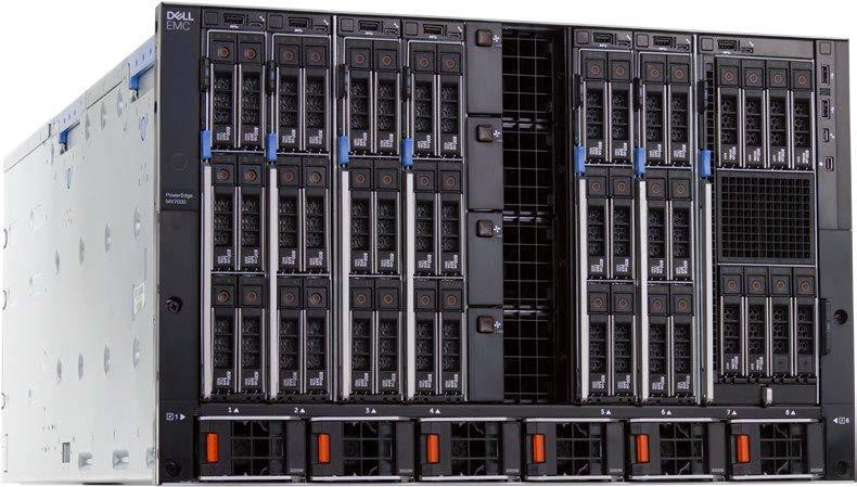
Image 1: The new PowerEdge MX7000 modular platform
The acoustical baffle is an optional, simple-to-install add-on that snaps to the rear of the MX7000 chassis directly behind the rear fans. When installed, the baffle improves the acoustical output of the rear fans and diffuses some of the airflow away from someone working behind the chassis. The acoustical baffle is specifically designed for noise-sensitive deployments that may require temporary or permanent noise mitigation. IT professionals surveyed on the performance of the baffle reported that it improved sound quality “to a kind of white noise”, and that it “removed shrill tones by muffling the higher frequencies”. Most importantly, when the baffle is deployed in conjunction with the Sound Cap profile in iDRAC, noise levels typically remain low enough to carry on a conversation within a meter of the chassis.
MX7000 Acoustical Baffle installation instructions
Installation of the MX7000 Acoustical Baffle is simple and straightforward:
- Access the rear of an MX7000 chassis.
- Align the acoustical baffle with arms facing (inwards) toward the rear of the chassis and optical window on the bottom.
- Locate the cut outs on each side of the rear of the chassis.
- Push the baffle until the tabs engage onto the chassis.
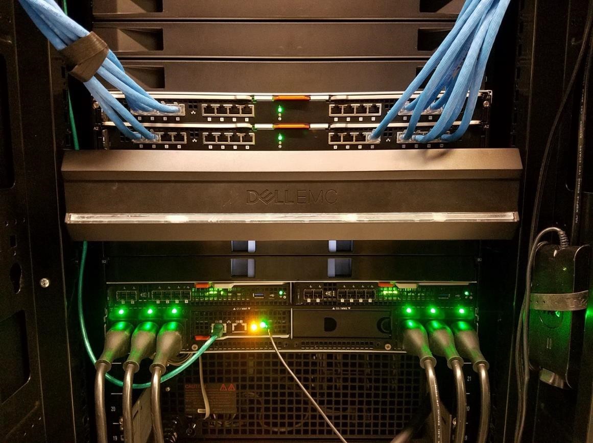
Image 2: MX7000 Acoustical Baffle installed at the rear of MX7000 chassis.
MX7000 Acoustical Baffle restrictions
- Although the geometry of the MX7000 Acoustical Baffle is optimized to minimize any impact to the cooling capability of the rear fans, the baffle is not recommended for systems configured with CPU’s that have TDP specifications greater than 140W1 operating in environments warmer than 35°C. In these situations, system performance may be impacted.
- The acoustical baffle is not designed as a cable management tool and cannot support the weight of cables. Do not lay cables on the baffle or affix cables to the baffle.
Conclusion
For noise-sensitive deployments, the optional PowerEdge MX7000 Acoustical Baffle can be installed to mitigate acoustical output. The acoustical baffle improves sound quality “to a kind of white noise”, as users have commented. Users comfortable with Data Center levels of noise need not install the optional acoustical baffle, but where quiet operation is paramount, the MX7000 Acoustical Baffle is highly effective.
Notes:
1. Performance of some low core-count processors with TDPs below 140W may also be impacted by the presence of the baffle in higher ambient environments. Reach out to your Dell representative for more information.

Direct from Development – PowerEdge MX-Series Optimizations for the Software Defined Data Center
Tue, 10 Nov 2020 23:17:51 -0000
|Read Time: 0 minutes
Summary
The Software Defined Data Center is emerging as one of the leading architectural approaches for customers who wish to cut costs, increase agility and improve reliability without incurring vendor lock-in. The new MX-Series Modular solutions from Dell EMC were designed specifically to enable SDDC by integrating key optimizations for Software Defined Storage and Software Defined Networking with the industry leading Dell EMC PowerEdge Server family.
Background
The term Software-Defined Data Center (SDDC) defines the extension of virtualization to all data center resources. According to Wikipedia, an SDDC virtualizes “all elements of the infrastructure – networking, storage, CPU and security and delivers them as a service.” The benefits include reduced acquisition cost, reduced operating cost, increased levels of automation with each component potentially provisioned, operated and managed through an application programming interface (API). Most customers have started the journey towards SDDC with the implementation of server based hypervisors like VMWare, Hyper-V and KVM for the compute layer and many have extended this concept to storage with Software Defined Storage (SDS) solutions. For these customers, the next stage in the journey will often be the virtualization of Network Services (SDN). The Dell EMC MX-Series has been designed specifically to assist customers with this journey.
MX Optimizations for SDS
Software Defined Storage (SDS) solutions aggregate disk storage local to each server into a highly reliable, extremely scalable, high performance storage pool that is easy to deploy and manage. This approach costs less, performs better and has helped many customers reduce the time it takes to deploy new solutions but has historically been a poor fit for blade environments due to their low disk counts.
The complexity of managing large numbers of servers led to the development of blade systems where multiple servers could be enclosed and managed from a single chassis. The challenge for many customers as they evolve to SDS based storage is that these systems were designed for the SAN based storage technologies available and simply do not offer the local disk capacities necessary for SDS.
With drive subsystems optimized primarily for boot functions, most blade designs offer only 2 drives. In designing the MX-Series, Dell EMC Engineers took the opportunity to rethink the entire architecture and to design a solution that not only exceeds the management efficiencies of existing blade solutions but adds in key design elements that make it an ideal solution for SDS environments.
MX SDS Capacity Enhancements
A key element of SDS optimization is capacity. Unlike other 2 socket blade solutions on the market, the Dell EMC PowerEdge MX740c offers up to 8 drives including 6 front-mount hot pluggable 2.5” drives and 2 internal SSD’s installed on the optional Boot Optimized Storage System (BOSS) controller.
For customers desiring the cost efficiency of traditional disks, this allows for up to 5 x 2.4TB SAS drives for a total of 12TB of raw capacity, 1 SSD for caching and then offers the optional BOSS controller to provide space for the operating system and log files.
For customers desiring maximum capacity and performance, the system can be configured for “All Flash” operation with raw capacities up to 23TB using 6 x 3.84TB SSD’s. The optional BOSS controller can again be utilized maintain the operating system and log files allowing all hot pluggable drives to be utilized for SDS.

Additional Expansion
For customers with even more demanding storage requirements, the optional MX5016s storage system can be added. With support for up to 16 additional hot plug SAS drives, this device can be used add drive slots to 1 server or to divide the drive slots between other servers in the enclosure to increase the capacity of an SDS solution.
Other considerations for optimized SDS
SDS solutions are designed to accommodate network bottlenecks however, it is logical that reducing latency and increasing bandwidth can also increase the efficiency of the storage pool by reducing the replication time required to protect the pool. “All Flash” environments in particular can deliver significantly higher Input/Outputs per second (IOP’s) than traditional disks and the subsequent increase in disk activity can more quickly be processed in an environment where network latency is reduced and/or network bandwidth is increased.
Dell EMC Engineers addressed both of these elements in the MX-Series. First, all compute devices have standardized on 25Gb/s Ethernet which more than doubles the throughput available with existing 10Gb/s technologies. Second, the MX-Series offers network switching options specifically designed to accommodate the full bandwidth of the solution with no oversubscription. With industry-leading latency rates of sub-600ns for the MX5108n and Sub-500ns for the MX9116n, the MX-Series also processes network transactions faster.
Note: an SDS solution can survive the failure of multiple disks but not the failure of all the disks. For this reason, Dell EMC Engineers designed the MX5016s to support a maximum of 16 drives and to allow the addition of multiple MX5016’s in a single enclosure to avoid the risk of creating a single point of failure for the entire SDS pool. This design dramatically reduces the impact of a storage sled failure. Each MX5016s has redundant, hot plug expanders and is connected to redundant SAS switches in the enclosure.
MX Optimizations for SDN
All MX switch options come enabled for SDN. Delivering on the promise of “Open Networking,” both the MX5108n and the MX9116n ship pre-configured with Dell EMC Networking OS10 but include ONIE, enabling the option for third party SDN solutions from Dell EMC Networking partners.
Conclusion
The Dell EMC MX-Series was designed specifically to help customers facilitate their move to a Software Defined Data Center. From compute, to storage through to networking, the solution has been designed to work seamlessly and deliver uncompromised performance, reliability and efficiency. Tying all of these elements together is the new Open Manage Enterprise management framework which is built on the same API’s that Dell EMC provides to customers for custom development. This open approach allows customers to integrate the MX-Series seamlessly within their own management tools and workflows or, use the interface provided by Dell. Most importantly, this “open” approach allows customers to avoid costly vendor lock-in.
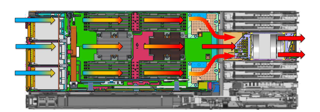
Direct from Development - PowerEdge MX7000 Chassis Thermal Airflow Architecture
Tue, 10 Nov 2020 23:06:50 -0000
|Read Time: 0 minutes
Summary
Creating a modular infrastructure that can efficiently cool the high-power, high- density workloads of today and tomorrow requires intelligent, scalable design.
Dell EMC’s PowerEdge MX7000 modular infrastructure meets these thermal challenges through an innovative, patent- pending chassis architecture design.
The Multiple Airflow Zone architecture of the new MX7000 chassis enables enhanced energy efficiency in the cooling of higher power and denser system configurations, extends the lifecycle of the chassis to accommodate multiple generations of future IT technology, and delivers excellent investment protection.
Modular infrastructures enable customers to be flexible in configuration, agile in management, and efficient in design, over several generations of compute, storage, and networking needs. The unique thermal design of the new Dell EMC PowerEdge MX7000 chassis ensures that customers can confidently grow over many generations of IT technology, satisfying forthcoming demands for scalable expansion and performance while providing excellent investment protection. The multiple airflow zone architecture of the MX7000 is engineered to ensure fresh air is delivered to each component of the chassis, enabling enhanced cooling of higher power and dense system configurations.
Chassis Architecture
The overall chassis architecture of the PowerEdge MX7000 uses dedicated, independent airflow paths for each critical subsystem (Compute, I/O, and Power Supplies) to provide fresh air to each individual zone. This design allows for expanded feature support, improved cooling efficiency, and the flexibility to scale with future needs. Figure 1 below provides a view of the front and rear of the MX7000 chassis with each zone highlighted.
- Zone 1 (Blue): Cooling air for the eight vertically-arranged Compute and Storage sled slots at the front of the chassis is drawn thru the chassis by five horizontally-arranged fans at the rear
- Zone 2 (Yellow): Four vertically arranged fans at the front of the chassis push cooling air into the I/O Modules (IOMs) at the rear of the chassis
- Zone 3 (Green): The bottom of the chassis is populated with up to six power supply units (PSUs) each with a dedicated fan and exhaust airflow path out the rear of the chassis
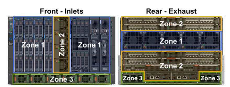
Figure 1: Front and rear view of PowerEdge MX7000 chassis with dedicated airflow zones highlighted
The orthogonal layout of these zones allows for simple, front-to-back airflow thru the chassis. By avoiding overly complex airflow paths to each subsystem, the overall chassis minimizes its impedance, allowing for increased airflow capability compared to traditional modular chassis architectures. Additionally, the independent airflow zones allow for more granular fan control algorithms which increase fan speeds only when and where it is needed to further increase efficiency.
Compute and Storage Sled Cooling
Compared with previous modular chassis from Dell and competitors, the MX7000 chassis contains no vertical midplane that would restrict the airflow through the chassis. Instead, sleds within the chassis mate directly with rear IOMs in A1/A2/B1/B2 slots through direct orthogonal interconnects. In the space between the A1/A2 and B1/B2 IOMs, the MX7000 80mm fan modules are directly ducted to the sleds to pull air through compute and/or storage sleds in Zone 1. Multiple chassis seals ensure that the low pressure generated by the rear 80mm fans stays within Zone 1. Containing the low pressure is critical in enabling the increased sled storage density with support for up to six 2.5” HDDs in the front end of the Dell EMC PowerEdge MX740c.
Figure 2 below provides a cross-sectional view of the chassis to highlight the Zone 1 airflow path thru a compute sled. Cool air enters thru the hard disk drive (HDD) bay of the sled before cooling the CPUs, memory, and peripheral components. The 80mm fan modules at the rear of the chassis pull air through the sleds and exhaust hot air out of the system. Fans are positioned in line with the critical heat loads, the CPUs, to avoid complex ducting and provide efficient cooling. Since there are no downstream components in this flow path, a large temperature difference is allowed across CPUs to maximize processor TDP support with headroom to scale with future generations.

Figure 2: Cross-sectional view of airflow through Zone 1 of the MX7000 chassis, showing cooling of Compute sleds. Air enters at front of chassis (on left) and exhausts thru rear of chassis (on right). Other airflow zones have been greyed out in this graphic.
Networking and I/O
Due to their internal layout, modular infrastructures have traditionally been forced to cool networking fabrics with preheated air from upstream components or through tortuous pathways that limit the amount of cooling airflow available. With limited airflow capability, the ability to support future networking and I/O technologies becomes more difficult as these technologies continue to advance at a rapid pace. In contrast, the MX7000 chassis has been designed for fresh inlet air delivery to all rear IOMs and Chassis Management Modules (CMMs) via four dedicated fan modules in the front of the chassis. The direct airflow path is shown in the cross-sectional graphic in Figure 3 (at the top of Page 3), which highlights airflow Zone 2. The four 60mm fan modules arranged vertically share a large plenum down the center of the chassis. An air ducts splits the airflow into an upper path which cools IOMs A1/A2 and a lower path to cool IOMs B1/B2/C1/C2 and CMMs. The fresh air entering these modules ensures the MX7000 chassis can run fans at lower speeds and operate over a wider range of environmental conditions as well as providing sufficient airflow capability for future networking technologies.
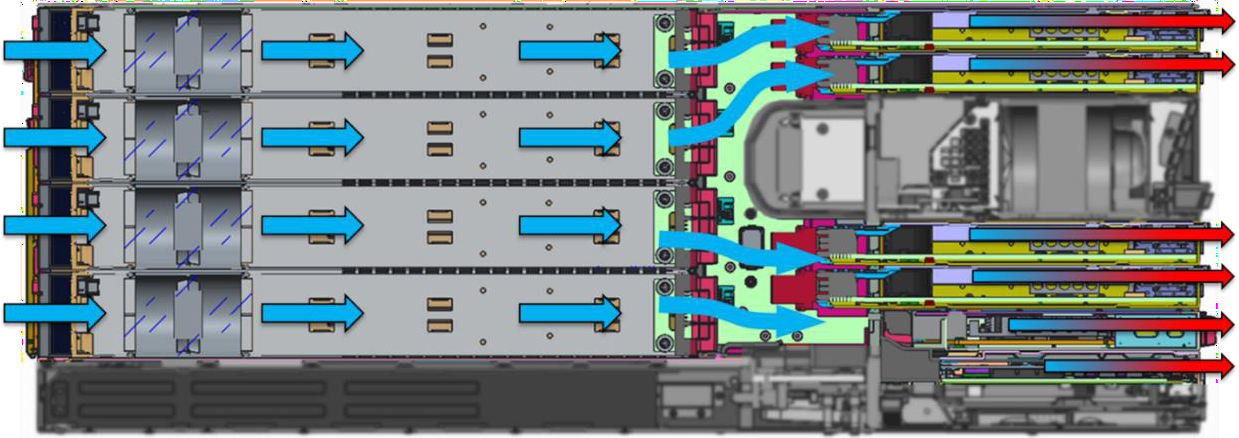
Figure 3: Airflow through Zone 2 of the MX7000 chassis, showing cooling of IOMs. Other airflow zones have been greyed out in this graphic.
Power Supplies
Power supplies in the MX7000 chassis benefit from a simple, independent airflow path at the bottom of the chassis, as shown in the cross sectional view of Figure 4 below. PSUs intake fresh air at the front of the chassis. Dedicated fans in the front of each PSU push airflow through dense electrical components and under the power connector at the back of the PSU. Since there are no downstream components to cool, PSUs can operate with very high exhaust temperatures of 60°C or higher. This thermal design helps ensure reliable delivery of up to 3000W supplied power in the dense form factor of each MX7000 PSU.
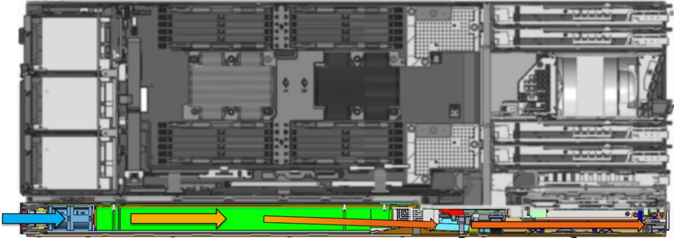
Figure 4: Airflow through Zone 3 of the MX7000 chassis, illustrating cooling of PSUs. Other airflow zones have been greyed out in this graphic
Conclusions
Traditional modular architectures have been characterized by complex airflow pathways that restrict airflow available to cool internal components, or require downstream components to operate within the constraints of preheated air from upstream components. This results in sub-optimal energy efficiency as well as places limitations on feature support, which in turn adversely impacts scalable growth for higher performance and/or capacity expansion.
The innovative multiple airflow zone architecture of the new PowerEdge MX7000 chassis overcomes these challenges and ensures that fresh air is delivered to each component in the chassis, enhancing cooling for higher power and denser system configurations. This design enables increased energy efficiency, extends the lifecycle of the chassis to accommodate multiple generations of future IT technology, and delivers excellent investment protection.

Direct from Development – PowerEdge MX-Series Fabric Management
Tue, 10 Nov 2020 19:37:43 -0000
|Read Time: 0 minutes
Summary
Storage technologies have been evolving at an accelerated rate driven primarily by changes in workloads. Solutions like virtualization, big data and in-memory databases utilize storage in very different ways. This evolution results in customers needing flexibility in their server infrastructure to meet these diverse needs.
The PowerEdge MX-Series has been designed specifically to reduce this complexity while at the same time, deliver the robust, flexible storage architecture that customers need to optimize for all of these environments.
Background
In many cases, workloads are now optimized for specific storage solutions. Virtualization environments benefit from the low latency, high capacity capabilities of Software Defined Storage (SDS). Scale-up In-memory Databases benefit from locally attached SSD’s for faster Database loading and Scale-out In-memory Databases require low latency shared storage solutions like SAN for shared access to data and fast database loading.
Adding to this complexity is wealth of options available for connection to storage environments. Traditional storage attach would include Fibre Channel (FC) or iSCSI and in recent years, Fibre Channel over Ethernet (FCoE). Conversely, newer technologies, like SDS, benefit from large pools of locally attached SAS storage using internal drive and/or JBOD enclosures.
MX storage connectivity options
To meet these diverse needs, the MX-Series has been designed to deliver a wealth of storage connectivity options. Traditional SAN connections are available through a pair of redundant Brocade 32Gb FC switches. In environments where SAS is required, the FC switches can be replaced with a pair of redundant SAS switches that connect to the optional MX5016s drive sled, with future support for external SAS JBOD enclosures. Traditional iSCSI, FCoE, and FC NPIV support is built into the integrated network switches and customers have the option to also use these devices to connect directly to a Dell EMC or 3rd party SAN.
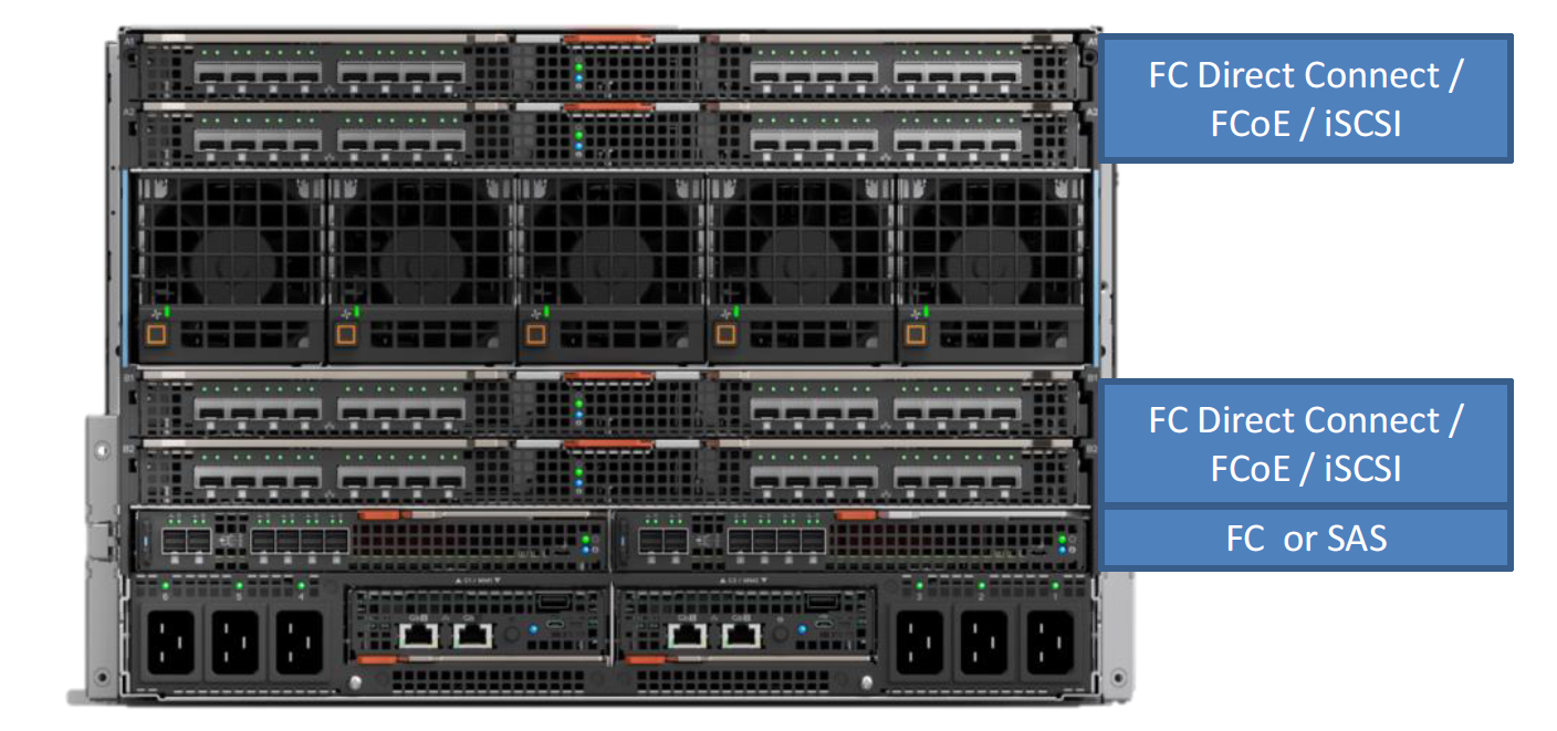
FC direct connect allows a Fibre Channel storage array to connect directly to the MX9116n Fabric Switching Engine (FSE) without the use of external FC switches. In this mode, SAN access becomes available to all servers in the connected chassis as well as all servers installed in the chassis that are connected to the MX Scalable Fabric.
Internal Storage expansion
For customers looking to take advantage of SDS or simply to utilize SAS as their primary disk storage, the new MX-series offers enhanced local drive support with up to 6 hot plug drives in the MX740c and 8 hot plug drives in the MX840c. Both models also support 2 internal mirrored M.2 drives with the optional BOSS card. Additional expansion is available with the MX5016s storage sled. This sled houses up to 16 x 2.5” dual port SAS drives which connect through a pair of redundant SAS switches to provide additional storage internal to the enclosure. Drives hosted in this sled can be dedicated to a single server, be divided amongst all of the servers or, have their capacity aggregated and shared amongst all of the servers in the enclosure in operating environments that support this mode. For more demanding environments, multiple MX5016s sleds can be added to a single enclosure to increase the number of disks available to the servers.
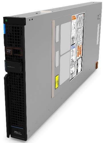
External Storage expansion
For customers looking to connect to an existing FC SAN, the optional redundant FC switches support connection speeds of up to 32Gb/s and integrate into existing SAN fabrics without compromise.
Integration with existing FCoE or iSCSI environments can be accomplished natively through the optional Ethernet switch options for the MX. For FCoE, these switches can be configured to pass traffic directly through to an external gateway. Additionally, the MX9116n FSE can be configured as an NPIV gateway to an existing Brocade or Cisco MDS SAN.
As noted above, the MX9116n FSE can also be directly connected to a Dell EMC or 3rd party FC storage array. This mode provides access to shared storage that is dedicated to the devices connected to the MX Scalable Fabric and reduces complexity and latency to serve demanding application environments like big data.
Conclusion
As workloads have evolved, storage technologies have been dramatically affected. Customers now find that they often require multiple storage options in their environment to meet this need. Optimizing storage for a virtualization environment often means deploying a Software Defined Storage solutions like Microsoft Storage Spaces, VMWare vSAN or Dell EMC ScaleIO. This approach requires large pools of server based storage devices. Optimizing for solutions like in-memory database can be more complex with scale-up solutions requiring extremely fast server based storage and scale-out solutions benefiting from SAN based storage solutions. Similarly, big data solutions may require extremely large pools of centralized storage to deliver the capacity necessary for large data-sets.
Regardless of the storage technology required, the PowerEdge MX-Series delivers. From multiple connection options for SAN to a robust, flexible architecture for server based storage, customers can configure the MX system for uncompromised storage optimization.

Direct from Development – PowerEdge MX-Series Fabric Management
Tue, 10 Nov 2020 19:04:14 -0000
|Read Time: 0 minutes
Summary
The Dell EMC PowerEdge MXSeries offers a wide range of connectivity options. Optional switch modules provide full L2/L3 switching capabilities and implement industry standard Open Networking technologies for true software defined networking. Additionally, customers can choose to enable SmartFabric Services to greatly reduce the administrative burden of switch management.
Background
The new PowerEdge MX-Series platform offers a wealth of networking options designed to scale from a single chassis to many. Offering a Future Forward design, MX-Series networking offers end to end 25GbE/100GbE connectivity while still maintaining backwards compatibility with 1/10/40GbE networks.
For single chassis requirements, the MX5108n Ethernet switch provides low latency, high bandwidth network access and supports a variety of uplink types.
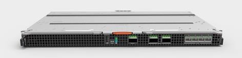
Figure 1. MX5108n
For more demanding environments, the MX9116n Fabric Switching Engine reduces latency and increases bandwidth even further, while scaling up to 10 chassis. This model adds 32G Fibre Channel and Fabric Expansion capabilities via Dell EMC’s Scalable Fabric Architecture. The MX9116n also supports heterogeneous rack servers and other Ethernet devices, for a total of 104 devices.
Both switches support Open Networking, Full-switch and SmartFabric operating modes.
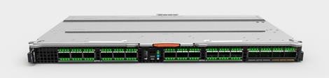
Figure 2. MX9116n
Each system supports ONIE, enabling the option for third party SDN solutions from Dell EMC Networking partners. Most installations, however, will be deployed with Dell EMC Networking OS10 Enterprise Edition, which can operate in two modes:
Full-Switch mode provides industry standard L2/L3 switching with full customization and can be configured using the Command Line Interface (CLI), API, or DevOps solutions such as Ansible.
SmartFabric Services is the latest Dell EMC Networking innovation and is designed to greatly reduce the complexity of fabric configuration, management, failure remediation and firmware updates. SmartFabric Services also provides I/O aggregation, Active-Active multi-pathing and physical topology validation.
SmartFabric Services
In SmartFabric mode, these devices provide I/O aggregation to eliminate complex upstream switch configuration. By providing Active-Active multi-pathing to all hosts, load balancing and fault tolerance is delivered seamlessly. In addition, error prone tasks like VLAN and priority assignments are attached to server profiles and drive automated Quality of Service (QoS) configuration on the switch. Management is achieved with a single CLI and/or API to manage multiple switches and multiple fabrics.
With an unprecedented level of automation for a Modular design, Firmware updates are managed at the “Fabric level” to ensure consistency and in the event of replacement, the new device will be updated automatically and physical topology confirmed before the new switch is brought on-line.
SmartFabric Services automatically detects misconfiguration and link level failure conditions and notifies the administrator of the error as well as corrective actions required. Upon resolution, the system will automatically “heal” the fabric once the conditions are resolved.
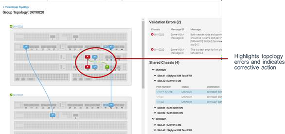
Scalable Fabric Architecture
One of the critical design elements that have made Modular servers so popular is their ability to consolidate administration functions for all servers into a single management console. The new MX Scalable Fabric Architecture extends this concept even further with the development of the new MX7116 Fabric Expander Module.
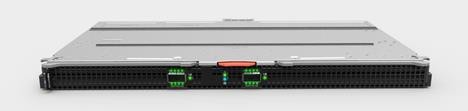
Figure 3. MX7116 Fabric Expander Module
With this innovation Dell EMC Engineers were able to deliver a robust fabric expansion solution that integrates with the MX9116n Fabric Switching Engine to connect up to 10 MX-Series chassis together into a single, manageable domain. Installed in pairs, full fault tolerance can be achieved without adding additional switches. This device is completely unmanaged, performs no switching functions, runs no OS, and has a latency of only 55ns. It reduces cabling and provides a seamless connection back to the MX9116n with no port to port oversubscription.
Conclusion
The Dell EMC MX-Series was designed specifically to help customers facilitate their move to a more automated, resilient and high performing infrastructure. For those customers not yet ready to make this move, traditional management process can be used to configure the networking elements of the MX-Series infrastructure using Full-Switch mode or Open Networking but for those looking for ease of use, self-healing technologies, automated configuration of VLAN and QoS as well as the convenience and cost savings of reduced administration, SmartFabric Services is the ideal solution.
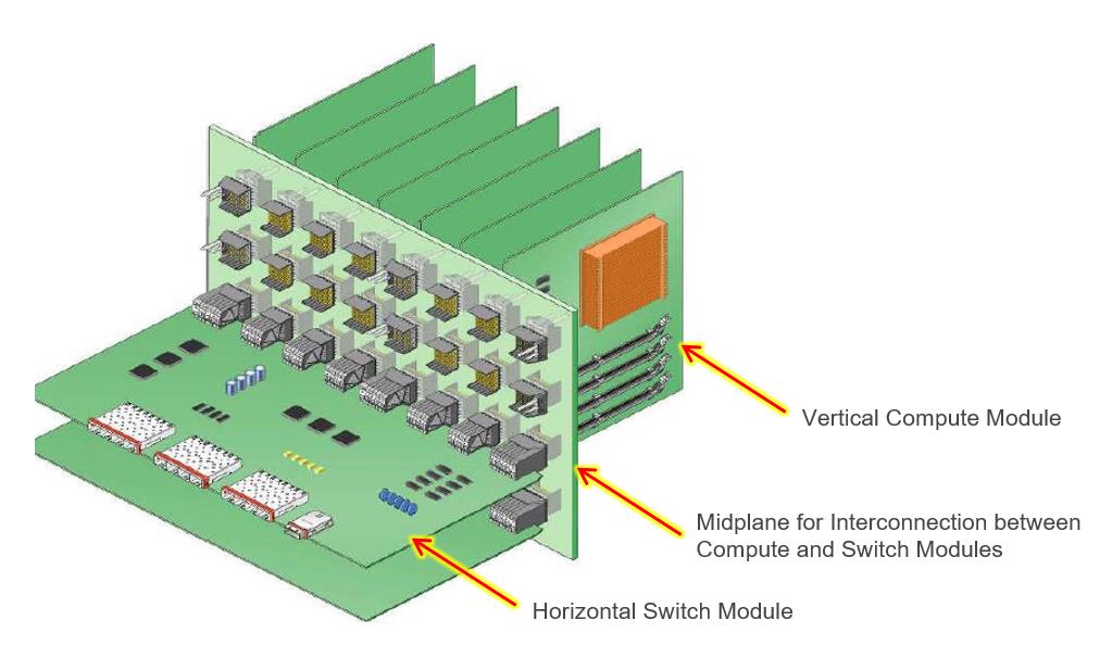
Direct from Development - PowerEdge MX7000 Direct Orthogonal Connectors
Tue, 10 Nov 2020 16:54:16 -0000
|Read Time: 0 minutes
Summary
The trend of increasingly higher- power processors and DIMMs creates challenges for traditional midplane architectures, particularly with regard to airflow and cooling, high speed signal transmission, and power delivery.
The new PowerEdge MX7000 modular platform eliminates the midplane and instead uses Direct Orthogonal Connectors for internal interconnection of compute, storage and switch modules.
Elimination of the midplane greatly optimizes airflow and enhances cooling. Signal transmission and power delivery are also improved by this new, innovative design.
Modular systems (such as the Dell EMC PowerEdge M1000e blade enclosure) integrating both compute/storage modules and switch (I/O) modules require an intricate method of interconnection within the chassis. A traditional interconnect architecture contains vertical compute/storage modules and horizontal switch modules, and a midplane enabling interconnection between these modules, as shown in Figure 1 below.

Figure 1: A traditional interconnect architecture using a midplane for interconnection of compute and switch (I/O) modules
A traditional midplane architecture such as the above has been an effective means of interconnect for many generations of servers, but a number of design challenges have been apparent and need to be overcome. Airflow has been a key challenge. Proper airflow is critical in order to ensure cooling of the compute modules, especially with current and future systems with high-power processors and DIMM’s. One attempt to resolve this has been to incorporate vent holes into the midplane to allow airflow. However, due to signal and power routing within the midplane, properly sized and effective placement of the vent holes is not always feasible. Moreover, signal integrity (SI) may be impacted when routing high speed signal traces long distances within the midplane. Even the use of Low Loss PCB material (such as Megtron 6) for high speed signal traces has limitations.
Consequently, in the development of the PowerEdge MX7000 Modular Chassis, the elimination of the midplane was a key design goal to improve airflow and signal integrity. To accomplish this, the implementation of Direct Orthogonal Connectors was selected to provide the interconnection between compute modules and switch modules. Fundamentally, Orthogonal Connectors provide a direct, right angle interconnection between a vertical PWA (Printed Wiring Assembly, also known as a Printed Circuit Board Assembly, PCBA) such as a compute module, and a horizontal PWA, i.e. a switch module, without a midplane. This direct interconnection is shown in Figure 2 below:
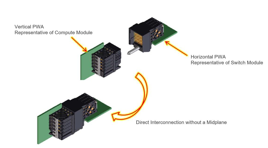
Figure 2: The PowerEdge MX7000 Orthogonal Connectors enable direct interconnection of compute/storage and switch (I/O) modules, liberating the architecture from the encumbrances and cost of a midplane.
The use of direct orthogonal connectors in the MX7000 eliminates airflow impedance caused by a midplane, and enhances overall airflow and cooling. The schematic in Figure 3 below illustrates how eliminating the midplane opens up internal areas of the PowerEdge MX7000 and improves airflow:
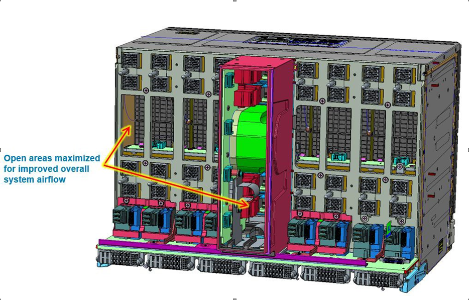
Figure 3: Elimination of the midplane in the PowerEdge MX7000 architecture opens up internal areas to improve airflow.
In addition to improving airflow and enhancing cooling, use of Direct Orthogonal Connectors in the PowerEdge MX7000 enables the formation of a comprehensive interconnection for high speed signal transmission between compute/storage modules and switch (I/O) modules, as well as for effective power delivery to these modules. Figure 4 below illustrates direct orthogonal interconnections between a vertical Compute Module and horizontal Switch Module, as well as power delivery using both Vertical and Horizontal Power Distribution PWA’s to those modules:
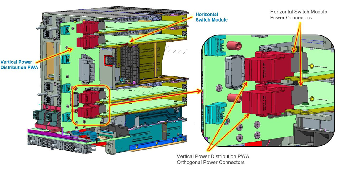
Figure 4: Schematic showing orthogonal power connectors for horizontal switch modules and vertical compute/storage modules.
Conclusion
While earlier servers and modular systems relied on a traditional midplane architecture, implementation of innovative Direct Orthogonal Connectors in the new PowerEdge MX7000 eliminates the midplane and greatly optimizes airflow through the compute and switch modules. This enhances cooling and ensures that current and future high-power processors and DIMM’s can be cooled more effectively, even at high ambient temperatures. Additionally, signal integrity will be optimal without being compromised by long Printed Circuit Board (PCB) traces, allowing for high speed signals (including PCIe Gen 4).
- For more information about airflow and cooling in the new PowerEdge MX7000, including its Multiple Airflow Zone design, see the Direct from Development tech note, PowerEdge MX7000 Chassis Thermal Airflow Architecture.

Direct from Development - Acceleration over Ethernet for Dell EMC PowerEdge MX7000

Mon, 09 Nov 2020 23:18:01 -0000
|Read Time: 0 minutes
Summary
Many of today’s demanding applications require GPU resources. This reference architecture incorporates GPUs to the PowerEdge MX infrastructure, utilizing the PowerEdge MX Scalable Fabric, Dell EMC DSS 8440 GPU Server and Liqid Command Center Software.
Request a remote demo of this reference architecture or a quote from Dell Technologies Design Solutions Experts at the Design Solutions Portal
Background
Emerging workloads, like AI represent a powerfully uneven series of compute processes, such as data-heavy ingest and GPU-heavy data training. When coupled with the fact that these workloads can demand even more resources over time, it becomes clear this complex new paradigm demands a new type of IT infrastructure.
Dell EMC PowerEdge MX7000 modular chassis simplifies the deployment and management of today’s challenging workloads by allowing IT to dynamically assign, move and scale shared pools of compute, storage and networking. It provides IT the ability to deliver fast results, not spend time managing and reconfiguring infrastructure to meet ever-changing needs. Composable GPU Infrastructure from Liqid powered by Dell Technologies expands the promise of software-defined composability for today’s AI-driven compute environments and high value applications.
GPU Acceleration for MX7000
For unique workloads like AI that require accelerated computing, the addition of GPU acceleration within the MX7000 is paramount. With Liqid, supported GPUs can be quickly added to any new or existing MX7000 compute sled, delivering the resources needed to effectively handle each step of the AI workflow including data ingest, cleaning/tagging, training, and inference. Spin-up new bare-metal servers with the exact number of GPUs required, and add or remove dynamically as needed, via Liqid software.
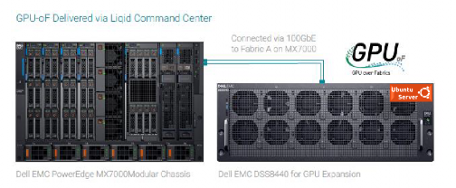
Essential PowerEdge Components and Ethernet Cabling
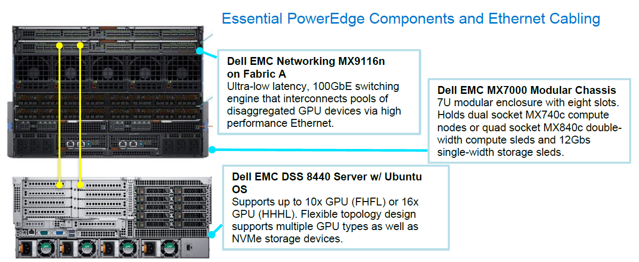
Liqid Command Center Software
The first step in the GPU expansion process, is to install up to 16x HHHL or 10x FHFL GPUs into a Dell EMC DSS 8440 server. As noted in the table 1, this solution supports several GPU device options. The next step is to connect the DSS 8440 to Fabric A on the MX7000 via 100GbE.
Liqid Command Center software resides on the fabric and will discover the GPU devices in the DS8440 and enable them for utilization by the MX7000 compute nodes. The users can distribute GPU-centric jobs from any compute sled on the MX7000 to GPUs located within the DSS 8440.
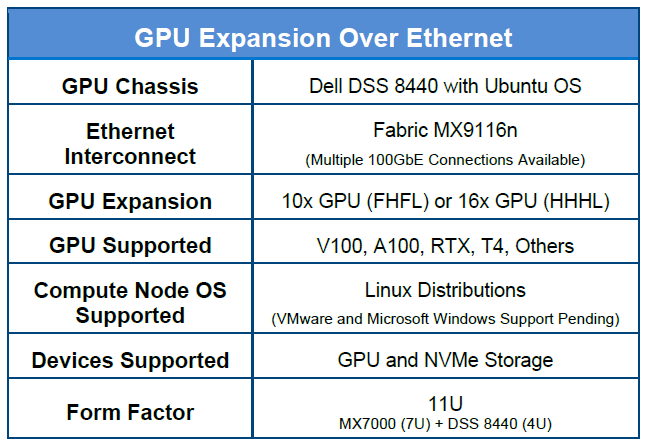
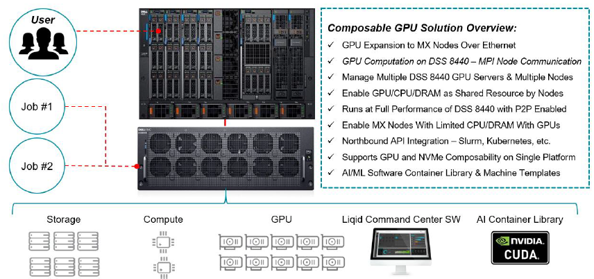
Accelerator Performance
To effectively demonstrate the performance of GPU accelerated MX7000 compute sleds, we tested it against DSS 8440 server with local GPUs and measured minimal to no overhead. The deep learning benchmark tests were run on the following networks: ResNet-50, ResNet-152, Inception V3, VGG-16. The DS8440 was outfitted with 8x NVDIA Tesla RTX8000 GPUs. The results clearly demonstrate that GPU enabled MX7000 delivers unrestricted performance on various industry standard benchmarks, using accelerator optimized Dell PowerEdge infrastructure.
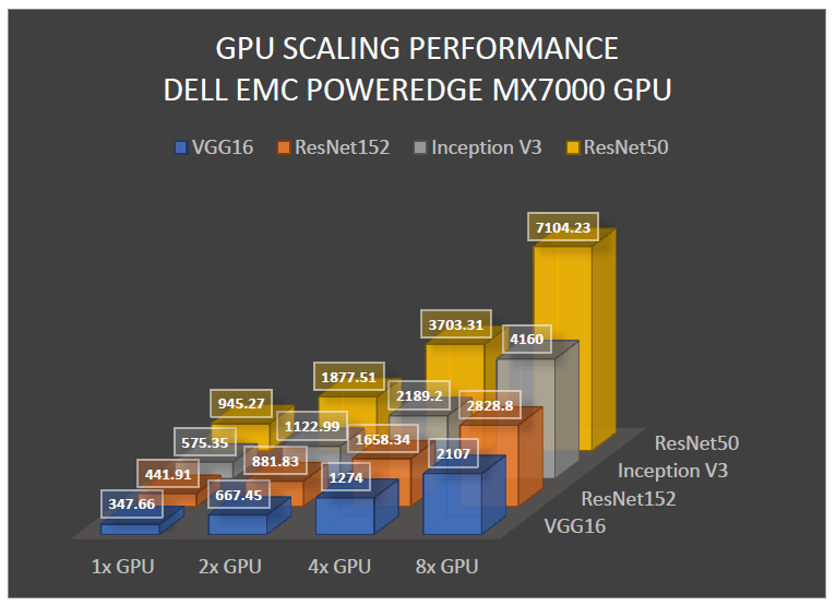
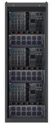
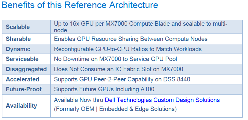
In Conclusion
GPU expansion for the MX7000 unlocks the ability to handle the most demanding compute workloads for both new and existing AI and HPC deployments. Liqid Command Center on Dell EMC PowerEdge Servers accelerates applications by dynamically composing GPU resources directly to workloads without a power cycle on the compute sled.

Reference Architecture: Acceleration over PCIe for Dell EMC PowerEdge MX7000
Thu, 12 Nov 2020 19:31:58 -0000
|Read Time: 0 minutes
Summary
Many of today's demanding applications require GPU resources. Our reference architecture incorporates GPUs to the PowerEdge MX infrastructure, utilizing the PowerEdge MX Scalable Fabric, Dell EMC DSS 8440 GPU Server, and Liqid Command Center Software. Request a remote demo of this reference architecture or a quote from Dell Technologies Design Solutions Experts at the Design Solutions Portal.
Background
The Dell EMC PowerEdge MX7000 Modular Chassis simplifies the deployment and management of today’s most challenging workloads by allowing IT administrators to dynamically assign, move and scale shared pools of compute, storage and networking resources. It provides IT administrators the ability to deliver fast results, eliminating managing and reconfiguring infrastructure to meet ever-changing needs of their end users. The addition of PCIe infrastructure to this managed pool of resources using Liqid technology designed on Dell EMC MX7000 expands the promise of software-defined composability for today’s AI-driven compute environments and high-value applications.
GPU Acceleration for PowerEdge MX7000
For workloads like AI that require parallel accelerated computing, the addition of GPU acceleration within the PowerEdge MX7000 is paramount. With Liqid technology and management software, GPUs of any form factor can be quickly added to any new or existing MX compute sled via the management interface, quickly delivering the resources needed to manage each step of the machine learning workflow including data ingest, cleansing, training, and inferencing. Spin-up new bare-metal servers with the exact number of accelerators required and then dynamically add or remove them as workload needs change.
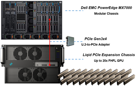 Figure 1 Essential PowerEdge Expansion Components
GPU Expansion Over PCIe | |
Compute Sleds | Up to 8 x Compute Sleds per Chassis |
GPU Chassis | PCIe Expansion Chassis |
Interconnect | PCIe Gen3x4 Per Compute Sled |
GPU Expansion | 20x GPU (FHFL) |
GPU Supported | V100, A100, RTX, T4, Others |
OS Supported | Linux, Windows, VMWare and Others |
Devices Supported | GPU, FPGA, and NVMe Storage |
Form Factor | 14U Total = MX7000 (7U) + PCIe Expansion Chassis (7U) |
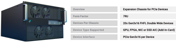 Figure 2
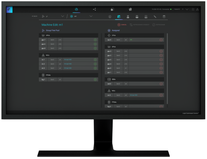 Figure 3 Liqid Command Center
Implementing GPU Expansion for MX
Figure 3 Liqid Command Center
GPUs are installed into the PCIe expansion chassis. Next, U.2 to four PCIe Gen3 adapters are added to each compute sled that requires GPU acceleration, and then they are connected to the expansion chassis (Figure 1). Liqid Command Center software enables discovery of all GPUs, making them ready to be added to the server over native PCIe. FPGA and NVMe storage can also be added to compute nodes in tandem. This PCIe expansion chassis & software are available from the Dell Design Solutions team.
Software Defined Composability
Once PCIe devices are connected to the MX7000, Liqid Command Center software enables the dynamic allocation of GPUs to MX compute sleds at the bare metal. Any amount of resources can be added to the compute sleds, via Liqid Command Center (GUI) or RESTful API, in any ratio (GPU hot-plug supported). To the operating system, the GPUs are presented as local resources direct connected to the MX compute sled over PCIe (Figure 3). All operating systems are supported including Linux, Windows, and VMware. As workload needs change, add or remove resources on the fly, via software including NVMe SSD and FPGA (Table 1).
Enabling GPU Peer-2-Peer Capability
A key feature included with the PCIe expansion solution for PowerEdge MX7000 is the ability for RDMA Peer-2-Peer between GPU devices. Direct RDMA transfers have a massive impact on both throughput and latency for the highest performing GPU-centric applications. Up to 10x improvement in performance has been achieved with RDMA Peer-2-Peer enabled. Below is the overview of how PCIe Peer-2-Peer functions (Figure 4).
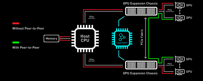 Figure 4 PCIe Peer-2-Peer
Bypassing the x86 processor and enabling direct RDMA communication between GPUs, realizes a dramatic improvement in bandwidth and in addition a reduction in latency is also realized. This chart outlines the performance expected for GPUs that are composed to a single node with GPU RDMA Peer-2-Peer enabled (Table 2).
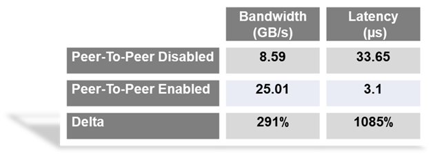
Application Level Performance
RDMA Peer-2-Peer is a key feature in GPU scaling for Artificial Intelligence, specifically machine learning based applications. Figure 5 outlines performance data measured on mainstream AI/ML applications on the MX7000 with GPU expansion over PCIe. It further demonstrates the performance scaling from 1-GPU to 8-GPU for a single MX740c compute sled. High scaling efficiency is observed for ResNet152, VGG16, Inception V3, and ResNet50 on MX7000 with composable PCIe GPUs measured with Peer-2-Peer enabled. These results indicate a near-linear growth pattern. and with the current capabilities of the Liqid PCIe 7U expansion sled one can allocate up to 20 GPUs to an application running on a single node.
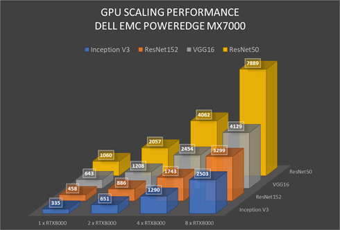 Figure 5 GPU Performance Scaling Comparison: MX7000 Leverages RTX8000 in PCIe expansion chassis measured with P2P Enabled
Conclusion
Liqid PCIe expansion for the Dell EMC PowerEdge MX7000 unlocks the ability to manage the most demanding workloads in which accelerators are required for both new and existing deployments. Liqid collaborated with Dell Technologies Design Solutions to accelerate applications by through the addition of GPUs to the Dell EMC MX compute sleds over PCIe.