
VCF components
VCF components
-
Each version of VCF includes a bill of materials (BOM) which dictates the versions for each component of the solution. VMware offers no ability to substitute. For example, even if there is a newer update for ESXi at the time of installation, VMware requires the version on the BOM. The versions are shown in Table 3.
Table 3. Bill of Material
Software Component
Version
Build Number
Cloud Builder VM
4.5.2
22223457
SDDC Manager
4.5.2
22223457
VMware vCenter Server Appliance
7.0 Update 3m
21784236
VMware ESXi
7.0 Update 3n
21930508
7.0 Update 3l
21424296
VMware NSX-T
3.2.3.1
22104592
VMware vRealize Suite Lifecycle Manager
8.10
21950667
Note: The BOM for VCF 5.x versions include VMware vSphere 8.x, which is supported with PowerFlex NFS for all VCF storage types and SDC for supplemental storage on custom PowerFlex nodes.
Network topology
At the physical layer, two Top of Rack (TOR) switches are used for redundancy and load-balancing purposes. There are four connections from each Dell host, two to TOR A and two to TOR B. VCF requires two of the connections to form the vSphere Distributed Switch (VDS).
The following table shows the different networks that are configured for this solution.
Note: All VLANs are tagged except for management (1109). An untagged VLAN requires setting VLAN ID to 0 in vSphere.
Table 4. Network VLANs
Network type
VLAN ID
Management
0
vMotion
1612
vSAN
1613
NSX-T Host Overlay
1614
PowerFlex topology
The PowerFlex 4.x system consists of five nodes, three for the MDM cluster and two for File. The characteristics of these servers are covered in Table 5.
Table 5. PowerFlex node configurations

VCF servers
The VCF environment as described in this paper consists of six servers, four for the management domain and two for the workload domain. Although the specifications of all servers are the same, they are listed below in Table 6 for completeness.
Table 6. VCF server configurations

vSAN
The following are the prerequisites to build the required vSAN storage setup for VCF:
- One SAS or SATA host bus adapter (HBA), or a RAID controller that is in passthrough mode or RAID 0 mode.
- For cache storage: One SAS or SATA solid-state disk (SSD) or PCIe flash device.
- For capacity storage: An All-flash disk group configuration that must have at least one SAS, or SATA solid-state disk (SSD), or PCIe flash device.
Generally, the first bullet point is standard for most servers so that is unlikely to cause a problem with vSAN. For the other two bullet points, there is a known issue where during the validation of the Planning Guide VMware is unable to identify devices for use with vSAN. VCF requires a ratio of one cache device to seven capacity devices. If the disks are available and visible on ESXi, but they are not recognized, it is possible to manually assign them as vSAN-eligible. This is a two-step process which is outlined below.
Formatting
The first issue is common during the validation step of the install. VMware reports that the devices on the servers have existing partitions, which render them ineligible for vSAN. To determine which devices are problematic, issue the command vdq -qH in ESXi to view all the devices and check the State row. An example is shown in Figure 5:
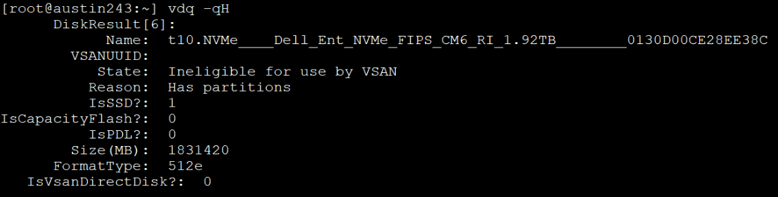
Figure 6. Ineligible for vSAN due to existing partitions
For this particular issue, the solution is to wipe the existing partition. This can be achieved by using the utility partedUtil to create a new gpt partition on the disk, clearing out the existing ones. The following is an example of the CLI command:
partedUtil mklabel /vmfs/devices/disks/t10.NVMe____Dell_Ent_NVMe_FIPS_CM6_RI_1.92TB________0130D00CE28EE38C gpt
While the command itself does not return any response, running the vdq command once more shows that the State of the disk is now eligible, as shown in Figure 6.
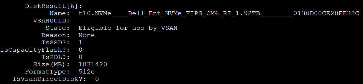
Figure 6. Eligible for vSAN
Capacity versus cache
The second issue for vSAN occurs when the devices are all of the same type, as they are on the servers in this environment. In such cases VMware treats all the devices as cache storage and thereby leaves no devices for capacity, which is required. This appears to be the most common of the two issues, and impacted the environment detailed in this paper. Fortunately, VMware provides a CLI command to “tag” devices as “capacityFlash” so that VCF will claim all tagged devices as capacity devices, and any non-tagged devices as cache, thereby satisfying the requirements for building the vSAN cluster. Since vSAN needs at least one cache device, it is best to tag all available devices for capacity, save one. Use the following command to tag devices:
esxcli vsan storage tag add -t capacityFlash -d t10.NVMe____Dell_Ent_NVMe_FIPS_CM6_RI_1.92TB________0130D00CE28EE38C
After running the command in Figure 7 and querying the disk, the row IsCapacityFlash? now shows a positive ‘1’.
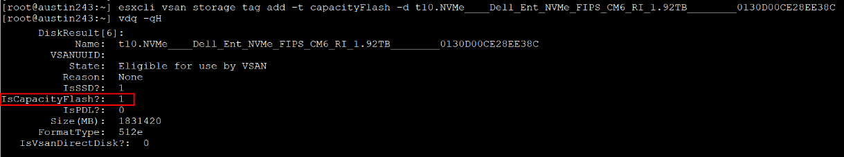
Figure 7. Setting the vSAN capacity tag
With the devices tagged, the Cloud Builder installer can create the vSAN cluster. In this environment, which includes 11 devices, VCF creates three vSAN disk groups for each host. Two of the disk groups will have three capacity devices and one cache device, and one of the disk groups will have two capacity devices and one cache device. One of these hosts is shown in Figure 8.
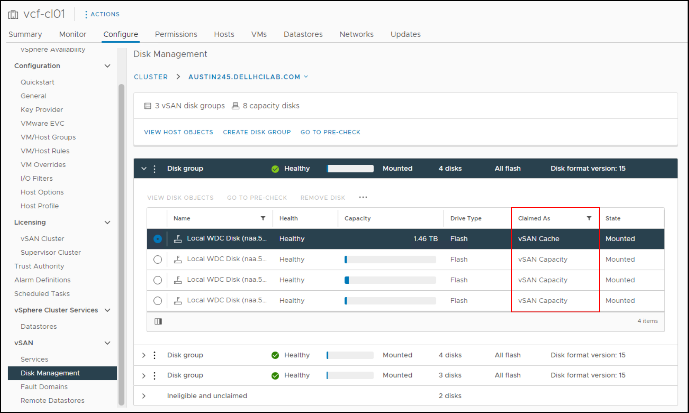
Figure 8. vSAN disk groups in VCF
Domains
VCF uses a concept called domains. Domains are essentially a set of resources such as servers, storage, and software. There are two types of domains in VCF: management and workload. There is one management instance per VCF. The management domain is the set of resources that runs VCF. The management domain is the control center of the environment, handling all aspects of life cycle management through an optional component, VMware vRealize Lifecycle Manager. The basic management functions are handled through the SDDC Manager, which is the interface to VCF, much like vCenter is to clusters of ESXi. VCF does not support controlling the management domain directly through the vCenter, though its hosts are managed by one.
Workload domains are deployed from the SDDC Manager and consist of their own vCenter, cluster, hosts, and storage. These workload domains are typically used to run the applications for a business. Unlike the management domain, the workload domain offers great flexibility in storage, so customers with array storage can take full advantage of the features of an array for their applications. The number of workload domains is only limited by the resources available to support them. An example of a VCF instance with two workload domains is shown in Figure 9.
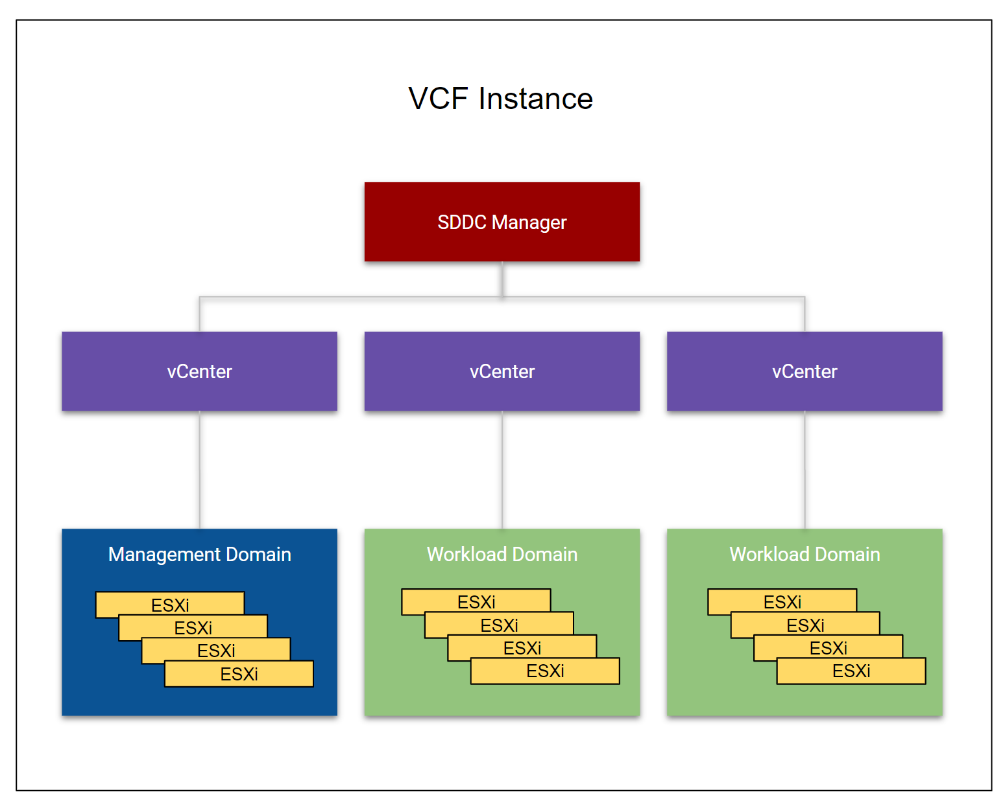
Figure 9. VCF instance with two workload domains
While the management and workload domains typically include separate hardware, for those customers with less server resources, or want a smaller footprint or even a POC lab, it is possible for the management domain to also be a workload domain. This is known as a consolidated architecture. In such a configuration the same vSAN that is used for the management domain can also be used for the workload domain, alleviating the need for more disk.
Storage
Storage plays an important role in VCF as vSAN is part of the solution. There are two different categories of storage in VCF, each serving different functions in the solution. They are called principal and supplemental. Principal storage is what is required to deploy a domain–management (vSAN only) or workload–or to deploy a new cluster in an existing workload (including the management domain). It can be of type vSAN, FC, vVols, or NFS. Supplemental storage is the storage that can be added to any existing management or workload domain to offer more space post deployment. Supplemental storage supports all the types of principal storage, as well as iSCSI and the PowerFlex specific SDC. These storage options are shown in Figure 10.
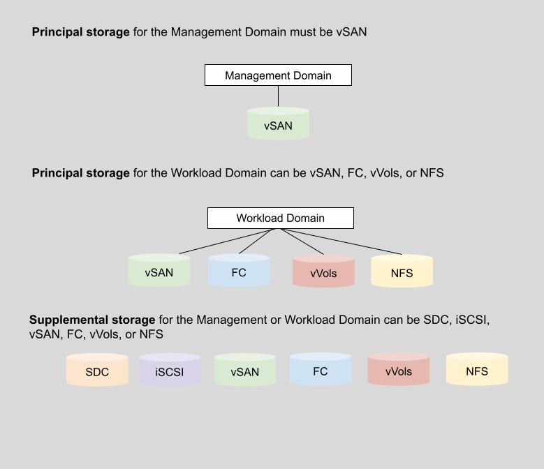
Figure 10. VCF storage options
As noted, vSAN is the only supported principal storage for the management domain. VMware requires vSAN in the management domain in order to have full control over storage life cycle management from creation to deletion. VCF does not provide this level of control for non-vSAN storage and thus requires the user to manage the life cycle. The entire VCF solution can run on vSAN with no other storage (and VMware strongly recommends this), but at a minimum vSAN must be used to deploy the management domain.
Note: The VCF release covered in this paper is 4.5.2. In the most recent VCF 5.x releases, VMware added support for NVMeoF for supplemental storage. It would therefore be possible to use NVMe/TCP on PowerFlex with VCF 5.x. See the VMware documentation for specific releases and their storage support.
Vendor storage support
VMware does not publish storage support for VCF by vendor, rather they rely on the VMware Compatibility Guide for Storage/SAN (https://www.vmware.com/resources/compatibility/search.php?deviceCategory=san). If the vendor is listed as supporting the protocol for the version of ESXi in the BOM, then it is supported with VCF. For example, Dell PowerFlex is listed as supporting ESXi 7 and 8 running on NFS, therefore NFS can be used as principal or supplemental storage with VCF.