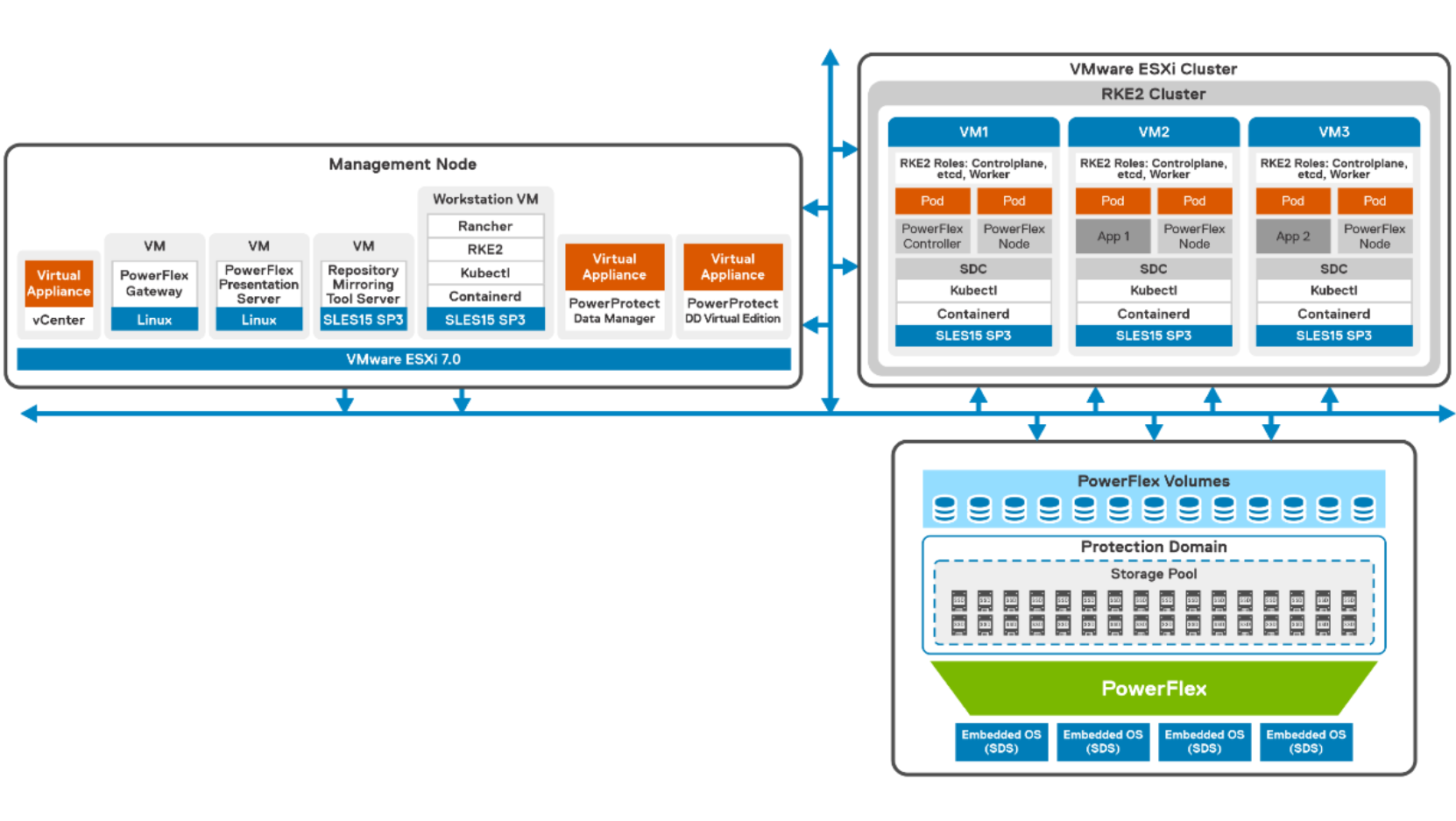
Logical architecture of RKE2 cluster on two-layer PowerFlex cluster
Home > Storage > PowerFlex > White Papers > SUSE Rancher and RKE2 Kubernetes cluster using CSI Driver on Dell PowerFlex > Logical architecture of RKE2 cluster on two-layer PowerFlex cluster
Logical architecture of RKE2 cluster on two-layer PowerFlex cluster
-
The following diagram shows logical architecture of the RKE2 cluster that is deployed on a two-layer PowerFlex cluster setup with four storage-only nodes and three compute-only nodes.

Figure 3. Logical architecture of RKE2 cluster in VMware environment
In this example, each storage-only node includes two Intel Xeon Scalable 12-core processors, 224 GB RAM, and eight 1.92 TB SSDs. From the PowerFlex standpoint, the Embedded operating system storage only nodes run the SDS component of PowerFlex to provide storage capacity. A single protection domain is created from these four SDS systems. A single storage pool is created within this protection domain from which persistent storage volumes can be provisioned for attachment to Kubernetes pods. The PowerFlex SDC component is installed into the VMware ESXi 7.x hypervisor running on the three compute only nodes, this provides access to volumes created within the storage pool.
In this solution, each of the virtual machines are installed with latest SLES15 Service Pack operating system. The RKE2 cluster is deployed on VMs in a VMware vSphere 7.0 cluster. For SUSE Rancher to work, the minimum hardware requirement to run Kubernetes node components is two CPU and 4 GB of memory. Considering the CPU and memory, it is recommended to host the different roles of the Kubernetes cluster such as, etcd , control plane, and workers on different nodes, so that they can scale independently from one another. In this solution, each virtual machine is configured with 2 virtual CPUs, 8 GB RAM, and thick provisioned disks on the PowerFlex backend storage.
For more information about configuration of PowerFlex nodes, see Configuration details.
