Home > Workload Solutions > SQL Server > Guides > Reference Architecture Guide—Consolidate and Simplify Mixed Database Workloads > Compute and network design
Compute and network design
-
ESXi host configuration
We installed and configured both the PowerEdge MX840c database servers—one for Oracle and one for SQL Server—with ESXi 6.7 U1 by using the Dell EMC customized ISO image (Dell Version: A03, Build# 10764712). This image is available on Dell EMC Online Support at VMware ESXi 6.7 U1.
Converged network adapter configuration
In this solution, the LAN and SAN traffic were converged within the blade servers by using four QLogic QL41262 dual-port 25 GbE CNAs. These CNAs support multiple network traffic protocols (Ethernet, FCoE offload, and iSCSI offload) and provide plenty of bandwidth to support the various LAN and SAN network functionalities in this solution. We partitioned these CNAs using NPAR, the network partitioning feature of the adapter, which enabled us to use the combined high network bandwidth available across the CNAs while also providing high availability. We partitioned the CNAs in both the Oracle and SQL Server hosts with the following functionality and bandwidth assignments:
Table 27. CNA configuration within MX840c database hosts
Mezz/CNA slot
Port number
Partition number
Partition type
Percentage bandwidth assigned
Application function
Mezz 1A
Port 1
Partition 1
NIC
0% (0 Gb)
None (initial ESXi management)
Partition 2
FCoE
100% (25 GbE)
Database SAN/FCoE 1
Mezz 1B
Port 1
Partition 1
NIC
0% (0 Gb)
None
Partition 2
FCoE
100% (25 GbE)
Database SAN/FCoE 2
Mezz 2A
Port 1
Partition 1
NIC
20% (5 Gb)
ESXi management and VM network uplink 1
Partition 2
NIC
20% (5 Gb)
Oracle/SQL vMotion uplink 1
Partition 3
NIC
60% (15 Gb)
Oracle/SQL public network uplink 1
Mezz 2B
Port 1
Partition 1
NIC
20% (5 Gb)
ESXi management and VM network uplink 2
Partition 2
NIC
20% (5 Gb)
Oracle/SQL vMotion uplink 2
Partition 3
NIC
60% (15 Gb)
Oracle/SQL public network uplink 2
Note: The NPAR feature, by default, creates four partitions on each port of the adapter. The partitions that are not listed in the table were disabled.
For detailed steps on how to create partitions on the QLogic CNAs, see one of the following documents:
- QLogic User's Guide for Fibre Channel Adapter, Converged Network Adapter and Intelligent Ethernet Adapters
- Dell EMC PowerEdge MX Series Fibre Channel Storage Network Deployment with Ethernet IOMs
Note: The MX I/O fabric slots A2 and B2 were not populated with any IOMs because they were not needed in this solution. As a result, the second port of each mezzanine or CNA card that internally connects to these fabric slots was unavailable or unused.
As shown in Table 25, we configured both database hosts with the following LAN and SAN design and best practices:
- LAN and SAN (FCoE) traffic on separate CNAs
- Two 25 Gb/s FCoE partitions (total 50 Gb/s) across two separate CNAs for high bandwidth and highly available SAN network connectivity
- Two 15 GbE NIC partitions (total 30 GbE) across two separate CNAs for high bandwidth and highly available LAN or database public network connectivity
- Two 5 GbE NIC partitions (total 10 GbE) across two separate CNAs for high bandwidth and highly available vMotion connectivity
- Two 5 GbE NIC partitions (total 10 GbE) across two separate CNAs for high bandwidth and highly available ESXi host management and VM network connectivity
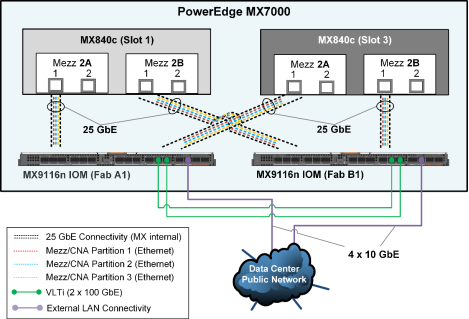
The following figure shows how the CNAs that are used for the LAN traffic (mezzanines in slots 2A and 2B within each of the MX840c blade servers) are connected internally to the MX9116n IOMs within the MX chassis. It also shows how the IOMs are connected to uplink switches for external LAN connectivity and access.

Figure 23. LAN network: Internal and external connectivity
As shown in the preceding figure, the first (5 GbE) NIC partition that was created on each of the mezzanine or CNA cards was used for ESXi host and VM management traffic, the second (5 GbE) NIC partitions were reserved for vMotion traffic, and the third (15 GbE) NIC partition on each of the CNAs was used for the database public traffic. To provide external connectivity and to provide sufficient Ethernet bandwidth for all three NIC functions across both the database ESXi hosts, we configured one external-facing QSFP28 (100 GbE) port on each MX9116n in 4 x 10 GbE mode. We uplinked the ports to spine switches in the data center using QSFP+ to SFP+ breakout cables (purple connectivity).
ESXi virtual network design
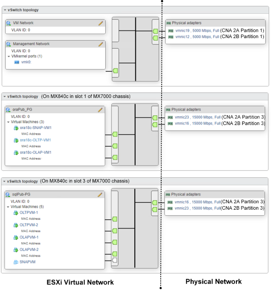
The following diagram shows the virtual switch design topology that we implemented on the ESXi hosts for the network connectivity that was required for both the Oracle and SQL Server databases. The vmnics in the following diagram are the respective NIC partitions that were created on the CNAs that appear as physical adapters within the ESXi hosts.

Figure 24. Virtual network design in the ESXi hosts
As shown in Figure 14, the virtual network design on the two MX840c database servers consists of:
- VM and management traffic—The VM network and ESXi management traffic uses the default standard virtual switch (vSwitch), which contains two default standard ports groups. The Management Network port group provides the VMkernel port vmk0 to manage the ESXi host from VMware vCenter Server Appliance. The VM Network port group provides the virtual interfaces for in-band management of the database VMs. For high availability and bandwidth, two 5 GbE uplink ports (partition 1) on two separate CNAs (in slots 2A and 2B) in the MX840c ESXi database servers were used for routing the management traffic.
- Public traffic—We created an additional dedicated standard vSwitch for the database public traffic on each of the ESXi database hosts for the Oracle and SQL Server databases. For high bandwidth, availability, and load balance, we used two 15 GbE uplink ports (partition 3) on two separate CNAs (in slots 2A and 2B) in the MX840c ESXi database servers for routing the database public traffic. Within each public vSwitch, we created one standard port group (oraPub-PG and oraSQL-PG, respectively) that provides the virtual network interfaces for the Oracle and SQL Server databases’ public traffic within their respective database VMs.
The Dell EMC customized ESXi 6.7 ISO image that we used contains the qedf FCoE driver for the QLogic QL41262 CNA. This driver ensures that the FCoE partition that we created on the QLogic CNAs for the SAN traffic was automatically recognized as FCoE virtual HBAs (vmhba64 and vmhba65) or storage adapters within the ESXi hosts, as shown in the following figure:

Figure 25. FCoE virtual HBAs or storage adapters recognized in ESXi hosts
FCoE-to-FC connectivity and zoning
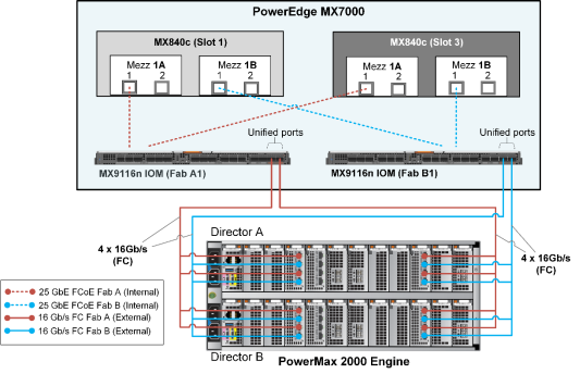
The following figure shows the internal FCoE connectivity between the CNAs or mezzanine cards within the MX840c blade servers and the MX9116n FSE IOMs. It also shows the external direct-FC connectivity between the MX9116n FSE IOMs and the PowerMax storage array.

Figure 26. FCoE-to-FC SAN fabric connectivity design
As shown in the preceding figure, we configured the first port on both the mezzanine cards in slots 1A and 1B of each MX840c server for FCoE traffic over 25 GbE internal connectivity to the respective MX9116n IOMs in MX fabric slots A1 and B1. We configured the two external-facing QSFP28 (100 Gb) unified ports on the MX9116n IOMs in 4 x 16 Gb/s FC breakout mode. The ports are directly attached to the PowerMax front-end FC ports using Multi-fibre Push On (MPO) breakout cables. This recommended SAN connectivity design ensures high bandwidth, load balance, and high availability across two FCoE-to-FC SAN fabrics—SAN Fabric A (red connectivity) and SAN Fabric B (blue connectivity).
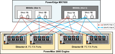
Dell EMC recommends single-initiator (FCoE partition on the CNA in this case) zoning of zone sets on the FC switches (MX9116n in this case). For high availability, bandwidth, and load balance, each initiator or CNA FCoE partition on the ESXi host is zoned with four front-end PowerMax storage ports that are spread across the two SLICs and the two storage directors, as shown in the following logical representation of zone sets:

Figure 27. FC zoning: Logical representation
As illustrated in the preceding figure, to provide the same high availability and equal storage front-end bandwidth access to both the Oracle and the SQL Server databases, we zoned each initiator with a unique front-end port distributed across the array. This design ensured that both the Oracle database ESXi host and the SQL Server database ESXi host had eight unique paths to the storage array.
For detailed steps on how to configure the FCoE-to-FC connectivity between the PowerEdge MX7000 and the PowerMax storage array, including best practices, see the following guides.
Note: Although the following FCoE-to-FC deployment guides use different Dell EMC storage arrays (Unity) and Dell EMC networking (unified) switches (S4148U), the concepts and network configuration steps are applicable to the PowerMax array and to the MX9116n IOMs that are used in this solution.
- Dell EMC PowerEdge MX Series Fibre Channel Storage Network Deployment with Ethernet IOMs
- Dell EMC Networking FCoE-to-Fibre Channel Deployment with S4148U-ON in F_port Mode Deployment Guide
Apply the recommended QoS (DCBx) configuration steps as specified in either of the two guides to ensure that the FCoE configuration is lossless. The QoS configuration is automatically applied when the two MX9116n IOMs are configured in Smart Fabric mode (Dell EMC PowerEdge MX Series Fibre Channel Storage Network Deployment with Ethernet IOMs). However, the configuration must be applied manually in Full Switch mode (Dell EMC Networking FCoE-to-Fibre Channel Deployment with S4148U-ON in F_port Mode). In this solution, we configured the FCoE-to-FC connectivity on the two MX9116n IOMs manually.
Multipath configuration
We configured multipathing on the ESXi 6.7 host according to the following best practices:
- Used vSphere Native Multipathing (NMP) as the multipathing software.
- Retained the default selection of round-robin for the native path selection policy (PSP) on the PowerMax volumes that are presented to the ESXi hosts.
- Changed the NMP round-robin path-switching frequency of I/O packets from the default value of 1,000 to 1. For information about how to set this parameter, see the Dell EMC Host Connectivity Guide for VMware ESX Server.
In vSphere 6.7, the administrator can add latency to the NMP configuration as a subpolicy to direct vSphere to monitor paths for latency. By default, the latency setting in vSphere 6.7 is disabled, but it might be enabled in vSphere 6.71 Update 1. Setting the path selection subpolicy to latency enables the round-robin policy to dynamically select the optimal path for latency to achieve better results. To learn more, see vSphere 6.7 U1 Enhanced Round Robin Load Balancing.
