Home > Storage > PowerFlex > White Papers > Oracle RAC on PowerFlex rack > PowerFlex deployment architectures
PowerFlex deployment architectures
-
PowerFlex software-define storage offers flexibility of deployment architecture to help best meet the specific deployment and architectural requirements. PowerFlex can be deployed in a two-layer (Server SAN), single-layer (HCI), or in storage-only architectures.
Two-layer (Server SAN) architecture
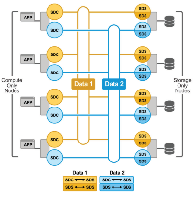
In two-layer architecture, nodes that provide storage capacity and host datasets are separated from nodes that host applications and workloads. PowerFlex manager provides LCM and IOTM for the entire infrastructure, including nodes that provide storage and nodes that host the applications. Compute and storage resources can be scaled by adding respective node to the cluster. This segregation of compute and storage resources can be helpful to minimize software licensing costs in certain situations. This architecture could be most suitable for hosting high-performance high-value databases and application workloads.
The two-layer approach is where the SDS and SDC components are on two different nodes chassis. The following figure illustrates the two-layer deployment of PowerFlex:

Figure 2. PowerFlex two-layer deployment
Single-layer (HCI) architecture
For this paper, the hyperconverged deployment option is taken into consideration.
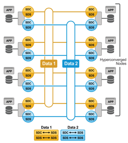
In this architecture, each node in the cluster contributes storage resources as well as hosts applications and workloads. This architecture allows you to scale your infrastructure uniformly and with a pre-defined building block that adds both storage and compute resources. PowerFlex Manager provides ITOM and LCM capabilities for the entire infrastructure. This architecture is most suitable for datacenter and workload consolidation.
The hyperconverged approach is where the SDS and the SDC reside on the same node chassis. In this type of deployment, the applications can reside on the same node.

Figure 3. PowerFlex single-layer (HCI) deployment
Storage-only architecture
In this architecture, PowerFlex provide only storage resources. Using PowerFlex storage-only nodes, a software-defined block storage environment is created that can be accessed and consumed by a number of applications and workloads that are hosted outside of PowerFlex cluster. PowerFlex Manager provides LCM and ITOM for the storage infrastructure. This is a suitable architecture where customer has existing compute infrastructure but needs high-performance SDS. This can be a starting point with the customer and may expand to a two-layer Server SAN deployment in the future as the external compute is migrated to PowerFlex.
