
Test failover without TimeFinder
Test failover without TimeFinder
-
Some customers require all disaster recovery testing to be true tests of their ability to fail over. This means the steps taken to test the failover process must be absolutely identical to the steps of the actual failover process. This requirement, therefore, assures no variables are missed in test failovers and consequently the test failover is a true test of the disaster recovery process. In the typical test failover scenario, local replication technologies are used on the remote site to make a copy of the R2 devices. The copy is then presented to the recovery ESXi cluster and the environment is powered on from those replica devices. In an actual SRM failover, the replication is halted from the protected site and the remote R2 device is presented to the host and the production VMs are brought up on the remote R2 device. These scenarios differ due to the fact that the test failover uses a copy of the SRDF replicated target and the actual failover uses the SRDF replicated target. To replicate a true test, the SRDF replicated target would be used to perform a test failover.
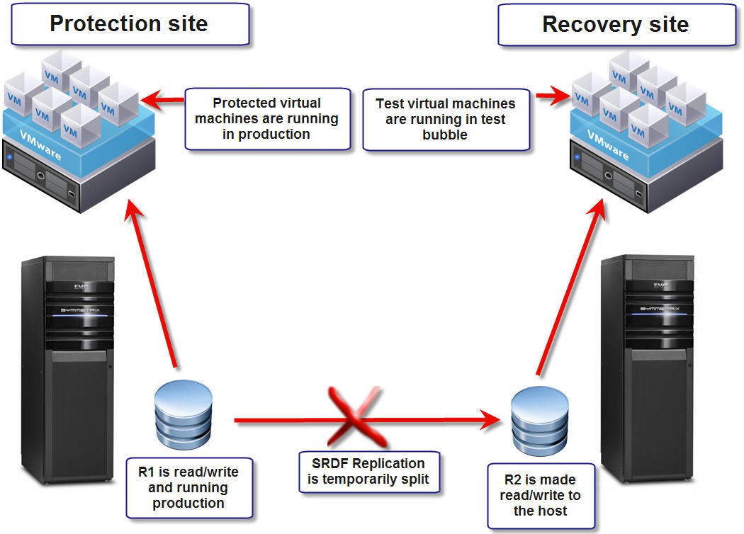
Fortunately, the SRA does allow this configuration. This feature enables the user to perform test failover operations directly off of the R2 devices at the remote site by splitting the link and write enabling the R2’s. The R2 is then presented (if not already) to the remote ESXi cluster for test recovery of the replicated virtual environment.
Note: Dell does not generally recommend using this method for test failovers. Since this process temporarily splits the link, remote data protection is consequently suspended and could lead to data loss or unavailability in the event of a simultaneous protected site failure. In addition, the clean-up operations after a test (resynchronization) can take a significant amount of time to complete and may require adjusting the storage timeout to a very high value (see Configuring advanced VMware SRM options). Before using this method of test failover, carefully consider the possible ramifications of doing so.
Note: Because of the active-active nature of SRDF/Metro, it is not possible to run a test failover with the R2 devices.
This section is divided into seven separate sub-sections. Note that Concurrent SRDF/Non-Star includes both 3-site SRDF/Metro and MetroDR:
- TestFailoverWithoutLocalSnapshots overview and configuration
- TestFailoverWithoutLocalSnapshots with 2-site SRDF
- TestFailoverWithoutLocalSnapshots with Concurrent SRDF/Star
- TestFailoverWithoutLocalSnapshots with Cascaded SRDF/Star
- TestFailoverWithoutLocalSnapshots with Concurrent SRDF/Non-Star
- TestFailoverWithoutLocalSnapshots with Cascaded SRDF/Non-Star
- TestFailoverWithoutLocalSnapshots with IgnoreActivatedSnapshots
TestFailoverWithoutLocalSnapshots overview and configuration
For a quick comparison, the traditional form of test failover using TimeFinder is schematically drawn out in Figure 75 and this form of test failover that does not use TimeFinder is laid out in Figure 76.
Figure 75. Traditional test failover with TimeFinder replication
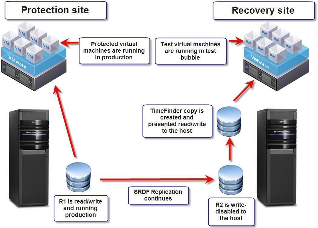
Figure 76. Test failover using SRDF without local replication
In order for the Dell SRDF SRA Adapter to perform a test failover in this manner (directly off the R2) an advanced option in the EmcSrdfSraGlobalOptions file must be altered. The option <TestFailoverWithoutLocalSnapshots>[33] must be set to “Enabled”. This will force the adapter to ignore any TimeFinder configurations in the options file and will then perform subsequent test failovers off of the R2.
TestFailoverWithoutLocalSnapshots with 2-site SRDF
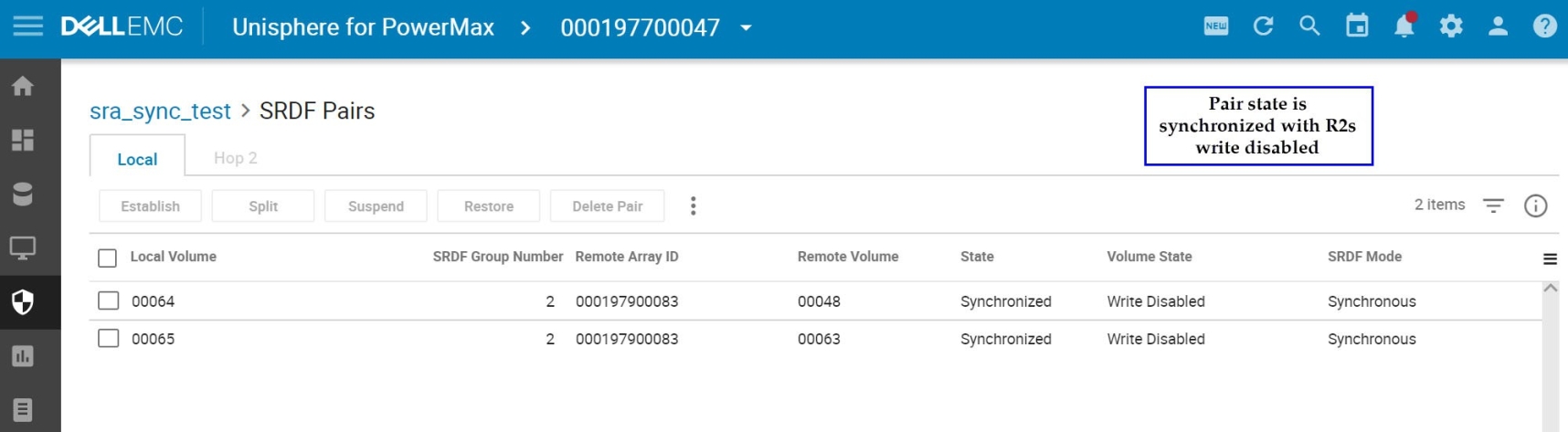
With 2-site SRDF, the replication state should be either “Synchronized” or “Consistent” (depending on the replication method) before test failover. Figure 77 show the replication and the device states before the test failover operation.
Figure 77. Replication and device state before test failover in Unisphere for PowerMax
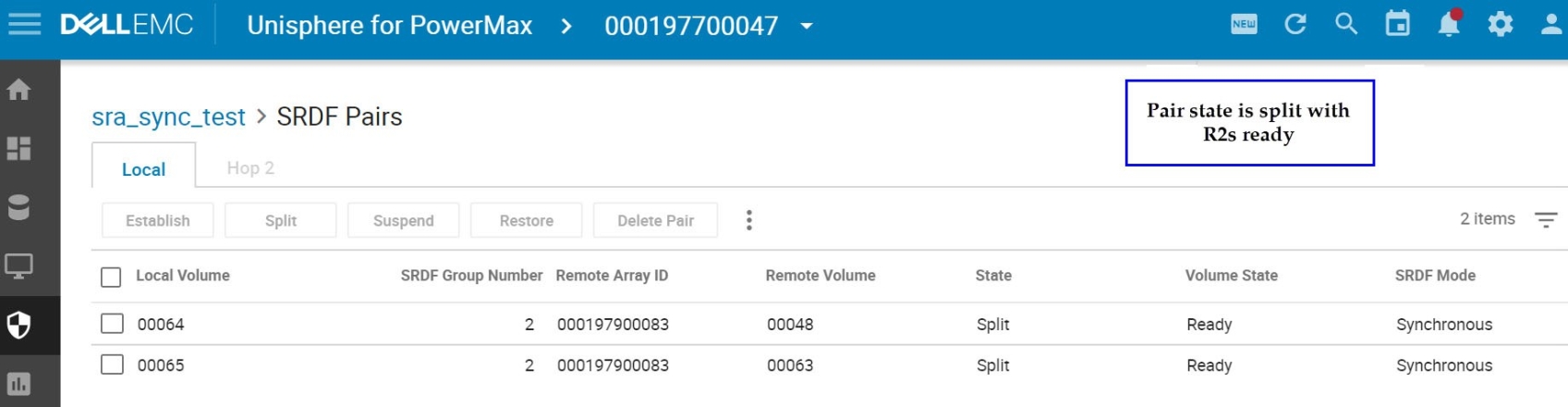
When the test failover is initiated, the SRA performs an “RDF Split” operation on the RDF link. This makes the R2 devices “Ready” as shown in Figure 78.
Figure 78. Split state of SRDF replication after test failover is initiated
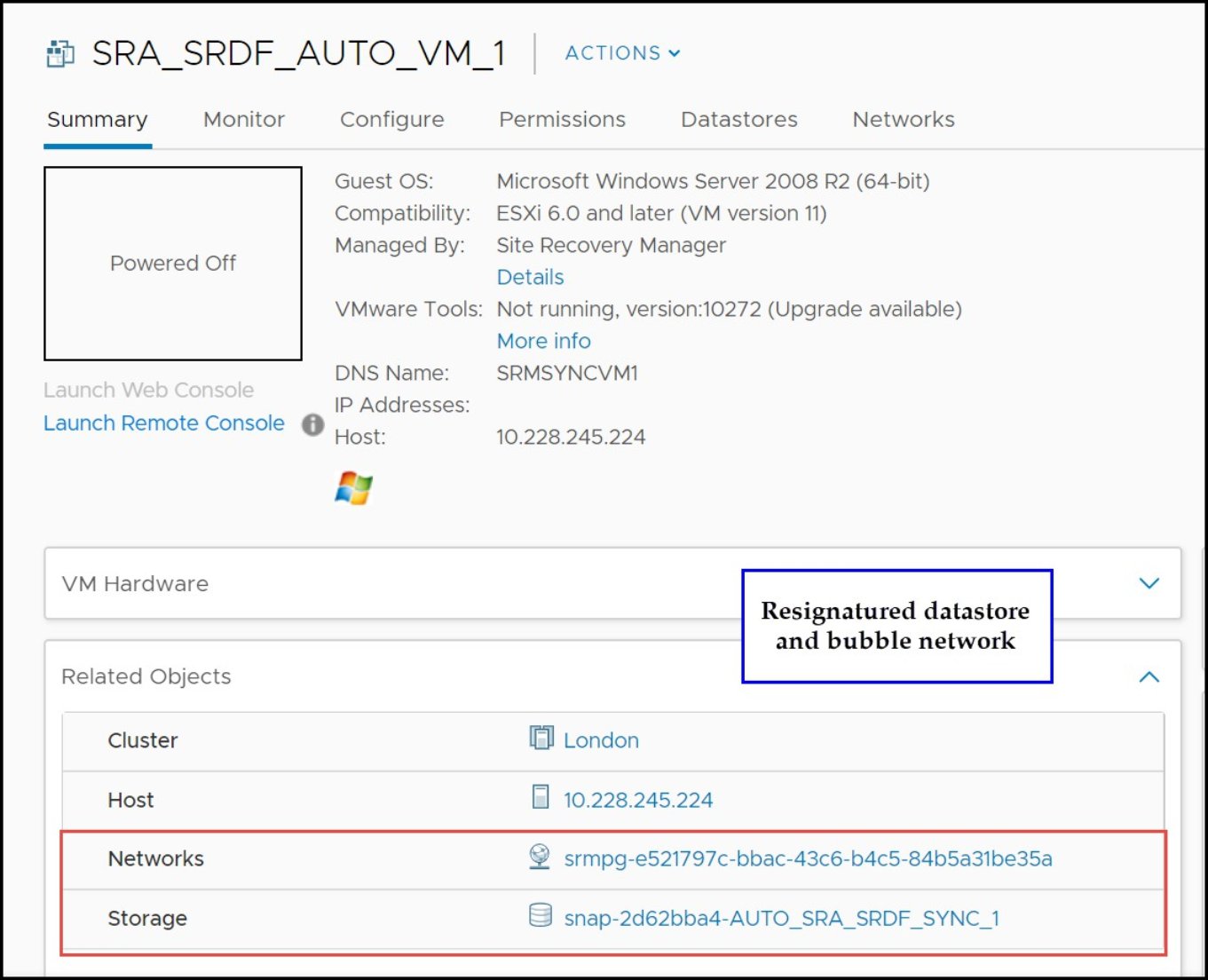
The SRA then initiates the test virtual machine recovery from the R2 devices directly. Looking at one of the VMs in the vSphere Client, it is apparent it is running on the R2 device in Figure 79.
Figure 79. Recovered test virtual machine running on the R2
When the user executes the “Cleanup” operation to complete the test failover process, the RDF link is incrementally re-established, making the R2 devices once again “Write Disabled” and replication re-initiates.
TestFailoverWithoutLocalSnapshots with Concurrent SRDF/Star
Since Star configurations are inherently more complex than 2-site SRDF, the process to use the R2 device requires different actions from the SRA.
Whether the recovery SRM server is on the Synchronous site or the Asynchronous site of the Star configuration, the process is essentially the same. What differs in the test failover workflow between the two different setups is which leg of the SRDF/Star setup is isolated and recovered.
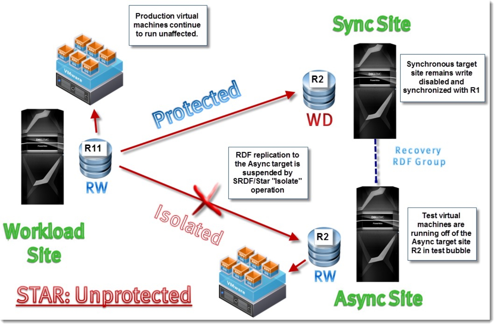
Figure 80 and Figure 81 show a diagram of the state of the Concurrent SRDF/Star environment when a test failover operation has executed with the TestFailoverWithoutLocalSnapshots option enabled. Figure 80 shows an environment with failover set to the Sync site (FailoverToAsyncSite is disabled) and Figure 81 shows an environment with failover set to the Async site (FailoverToAsyncSite is enabled).
Figure 80. TestFailoverWithoutLocalSnapshots enabled for Concurrent SRDF/Star to the Sync target site
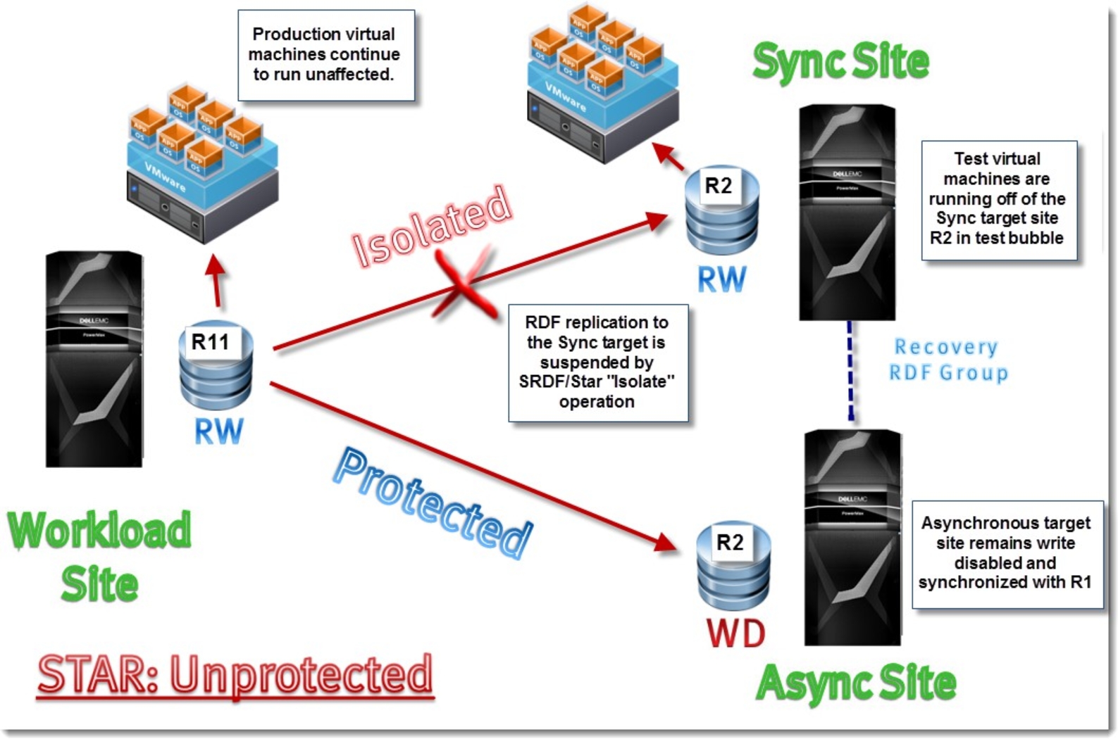
Figure 81. TestFailoverWithoutLocalSnapshots enabled for Concurrent SRDF/Star to the Async target site
For the purposes of demonstration, the following example will be a test failover run off of the Synchronous site devices.
Before a test can be executed, both active links of the Concurrent SRDF/Star configuration must be in the “Protected” state. If either link is in a state besides “Protected” the operation will fail.
Note: The overall Star state can be “Protected” or “Unprotected” for test failover but it is highly recommended that the Star state be in a “Protected” state. It should also be noted that if the Star state is “Unprotected” before the test failover, the SRA will fully protect Star during the cleanup stage regardless of the initial Star state.
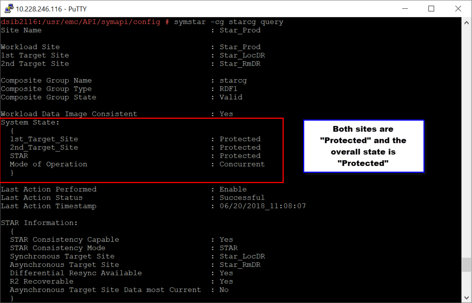
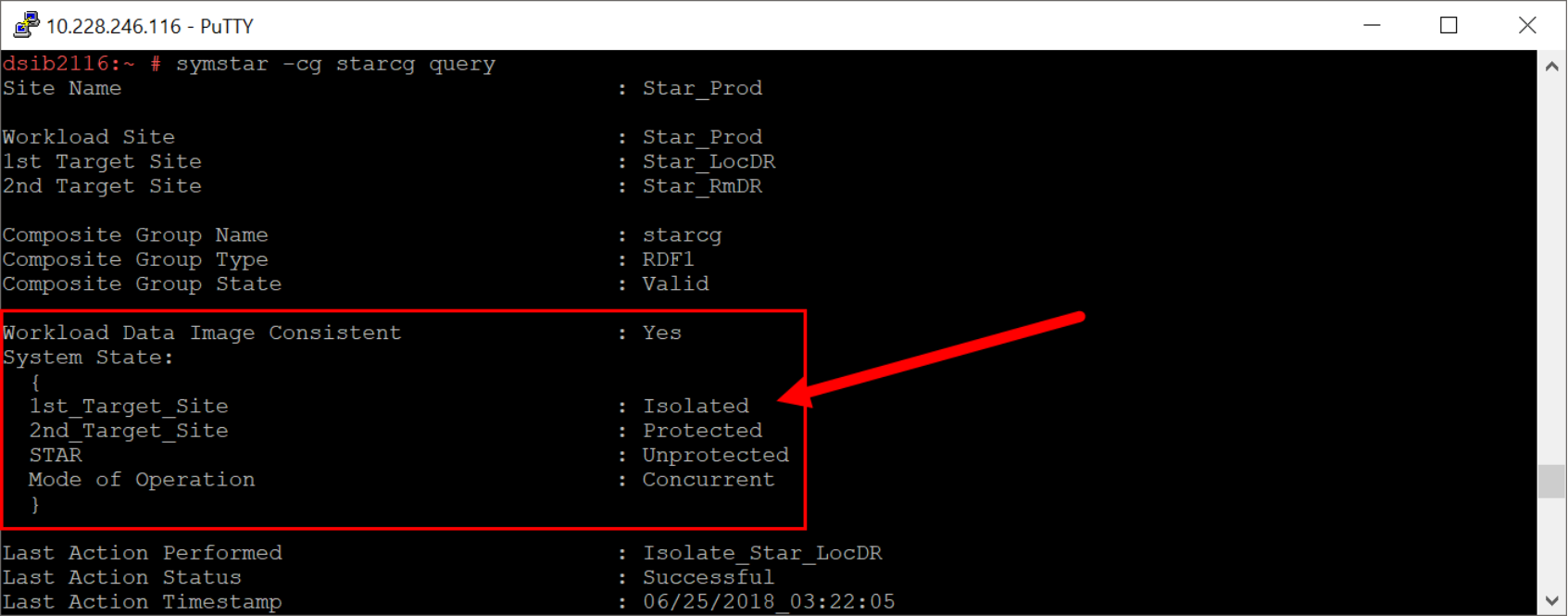
An example of a Concurrent SRDF/Star configuration prior to test failover can be seen in a screenshot in Figure 82. It should be noted that both active links are in the “Protected” state[34] and the overall Star state is also “Protected”.
Figure 82. Concurrent SRDF/Star before test failover
Once the test failover begins the SRDF SRA will disable Star (if not already in the “Unprotected” state). Then, depending on whether the recovery VMware environment is at the asynchronous target site or the synchronous target site the SRDF SRA will perform a Star “isolate” operation on the target devices. The “isolate” operation splits the RDF pairs and sets the R2 devices to Read/Write enabled allowing them to be used by the recovery environment.
From this point, the recovery operation proceeds normally. The expected state of a Concurrent SRDF/Star environment after a test operation but before a cleanup can be seen in Figure 83.
Figure 83. Concurrent SRDF/Star before test failover cleanup
The screenshot shows three things:
- An “Unprotected” overall Star state
- An isolated Synchronous target site
- A protected Asynchronous target site
This shows that the VMware environment is at the Synchronous site and that the devices in that location are R/W enabled while the asynchronous target site devices are unaffected.
Once the test failover has completed and all desired application tests are verified, the test failover can be ended and reverted by clicking the Cleanup operation button. During the cleanup operation, the SRDF SRA will execute the following Star operations:
- Disconnect the appropriate target site. This is required because the subsequent connect operation requires the site to be in the “Disconnected” state.
- Connect the target site. This will resume incremental replication to the target site and overwrite any changes made to the R2 devices with the data from the R11.
- Protect the target site. This will re-enable consistency to the target site.
- Enable/protect Star. The last operation will be to fully enable Star to revert the environment back to the protected state.
[33] TestFailoverWithoutLocalSnapshots and TestFailoverForce are not supported for simultaneous use.
[34] The target sites being in a protected state is a hard requirement