Home > Workload Solutions > Computer Vision > Guides > Design Guide—Flexible Computer Vision Solutions with Dell APEX Infrastructure > Ipsotek architecture
Ipsotek architecture
-
The Ipsotek VISuite Computer Vision platform extracts metadata from RTSP video streams, allowing you to improve response times, drive operational efficiencies, and generate new revenue streams. This intelligent capability produces alarms for specific behaviors and events, allows operators to perform forensic searches, and generates dynamic dashboards.
VISuite supports multiple use cases and can automatically generate alerts for operators to manage and log. For example, in airport-specific scenarios, the workflows include intrusion into aircraft-only zones, driving violations, and speeding. Alerts can be displayed on dynamic dashboards and updated according to operational requirements. VISuite can also be integrated with an email system to notify managers when certain events have occurred.
Scale-out architecture
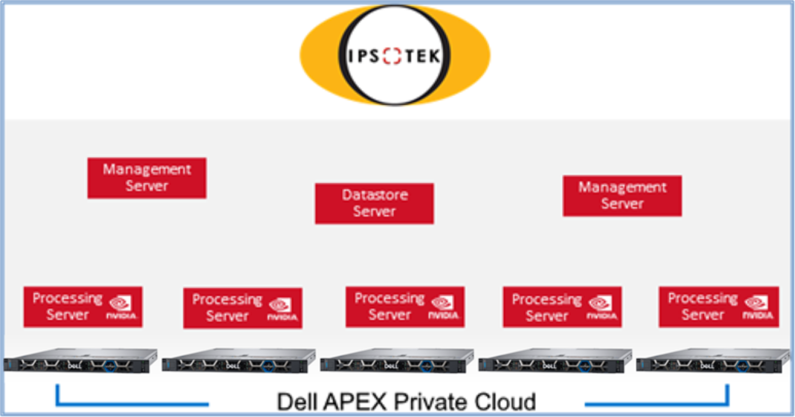
The Ipsotek VISuite system architecture consists of Management Nodes, Processing Nodes, and Database Nodes that are interconnected as shown in Figure 5. There are also services that manage rules and user interfaces, perform Video Analytics, and provide event and metadata storage, respectively. These roles could be deployed in a distributed manner and/or coexist on the same physical or virtual server.

Figure 5. Ipsotek scale-out architecture
Supported hardware redundancy
- N:N redundancy for active/active operation with zero downtime.
- Requires hardware duplication.
- N+1 redundancy for Processing Nodes.
- Requires load balancing.
Note: Redundancy does not require a software license.
Configuration best practices
The following guidelines are based on previous internal testing and reports from customer field experience. None of these guidelines were exceeded during testing.
Virtual Machines
- Each VM is configured to the specifications provided by Ipsotek.
- Each processing node is presented a full A16 card in passthrough mode.
- Uses a maximum of two processing nodes per node.
CPU
- Do not over allocate vCPUs.
Storage
- All Ipsotek nodes leverage the vSAN storage for operating system and auxiliary drives.
- Data is protected with a RAID 5 storage policy to provide maximum performance and protection with the trade-off of reduced available capacity.
Networking
- No network limits for Ipsotek. Sufficient bandwidth is needed at the processing nodes to consume the camera streams.
High availability
It is critical to design a high availability deployment of Ipsotek to avoid loss of alerts during an unplanned outage.
HA options
It is possible to configure Ipsotek in two modes:
- N:N architecture
- N+1 architecture
Ipsotek N:N architecture
The N:N Architecture involves provisioning a full clone of all VMs in the Ipsotek system. This involves a full duplication of all servers in the cluster running on separate hardware. One cluster acts as the primary and both clusters have connectivity to the camera streams. When running two identical clusters, Ipsotek has logic to ensure that configuration and alarms are synchronized to avoid duplication. Use this architecture when full redundancy is required.
Ipsotek N+1 architecture
The Ipsotek N+1 Architecture provides high availability within a single cluster. In this configuration, multiple management VMs are created and multiple Processing nodes are configured as a cluster.
With this approach, the processing nodes automatically join the cluster when they are booted. When they join the cluster, the Processing nodes start to process camera streams. The camera streams are load balanced by the Management cluster to allow an even distribution of workload across the cluster.
Ipsotek roles
The Ipsotek system is made up of multiple roles. Some of the critical roles for CV are:
Role
Supports
HAComments
Management Node
Yes
Central administration of the Ipsotek Cluster. Multiple nodes run in an Active/Passive manner using a Windows failover cluster.
Processing Node
Yes
Node where CV analytics is performed. Multiple processing nodes exist across the cluster. Workload is balanced across the nodes.
Database Node
Yes
Storage location for all Ipsotek config and metadata. Multiple nodes can be added together to form a cluster.
Note: A minimum of three data nodes is required to form a cluster. Only one was used for this testing.
The recommended approach for Ipsotek in a virtualized environment is to enable a GPU as a passthrough device. This means that it is not possible to easily migrate an Ipsotek processing node across the compute cluster. To combat this requirement, all four active nodes in the cluster must have a processing node configured. It is critical not to overload the four nodes and to allow enough capacity so that one of the nodes can become unavailable while the workload is still being processed.
VM designs
This section details the VMs on which the different roles reside:
VM name
Cores
Memory
GPU
Storage
OS
Role
ipso-mgmt-1
8
34GB
None
200GB
Win 2019 Server
Ipsotek Management Node
ipso-db-1
16
64GB
None
200GB
Win 2019 Server
Ipsotek Database Node
ipso-ps-1
24
64GB
1 x A16
c:\ 200GB d:\ 400GB
Win 2019 Server
Ipsotek Processing Nodes
High level architecture
The distribution of Ipsotek VMs is managed by DRS, except for the processing nodes. The processing nodes cannot be migrated easily across the cluster because they require passthrough GPUs.

Figure 6. Ipsotek VMs across the Dell APEX Private Cloud cluster
