This section details the recommended minimum hardware requirements for the network. This example shows Dell PowerSwitch Z9264F-ON spines and Dell PowerSwitch S5232F-ON leafs . However, all Dell PowerSwitches support Ansible automation.

This section details the recommended minimum hardware requirements for the network. This example shows Dell PowerSwitch Z9264F-ON spines and Dell PowerSwitch S5232F-ON leafs . However, all Dell PowerSwitches support Ansible automation.
To demonstrate the features of a typical Layer 3 underlay or Layer 3 border gateway protocol (BGP) Ethernet virtual private network (EVPN), this PoC uses a leaf-spine architecture. In a leaf-spine architecture, a series of access layer switches form the leaf layer. These switches are connected to a series of spine switches. Each leaf connects to each of the spine switches. The spines do not connect to one another when using the routed leaf-spine example in this deployment. Instead, leaf switches are deployed as a bridge between the server and the core network. The design ensures that leaf switches are no more than one hop away from one another, minimizing latency and the likelihood of bottlenecks. Furthermore, given any single-link failure scenario, all leaf switches retain connectivity to one another through the remaining links.
The connections between spine and leaf switches can be Layer 2 or Layer 3. Each leaf connects to all spine switches, so the total number of connections equals the number of leaf switches multiplied by the number of spine switches. The deployment scenario in this guide uses Layer 3 connections. Therefore, the leaf layer is the Layer 2/Layer 3 boundary for this topology.
The following figure shows the switches and interconnections for a Layer 3 network:
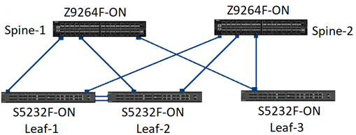
The following physical concepts apply to all leaf-spine topologies:
The Ansible control host communicates with the switches through the out-of-band (OOB) interface. To reduce complexity, the management network that is detailed in this PoC is a simple Layer 2 network on a single subnet.
The following diagram shows the management network and required connectivity:
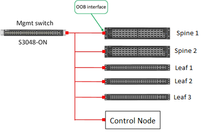
In this PoC, we assign the following IP addresses to the switches:
| Switch Name | IP Address |
| spine1 | 94.107.15 |
| spine2 | 94.107.14 |
| leaf1 | 94.107.13 |
| leaf2 | 94.107.12 |
| leaf3 | 94.107.11 |
A control node is a Linux server running Ubuntu Server with Ansible installed. The required Ansible roles are also installed in the system. The control node is used to manage remote Dell SmartFabric OS10 switches.