
Use cases
Use cases
-
This section provides a description of the use cases that we used to validate the correct behavior of the NF after deployment.
NRF use cases
This section describes the objective, procedure, and expected results for NRF use cases.
Objective: Registration of an NF profile in NRF
The following figure shows the call flow:
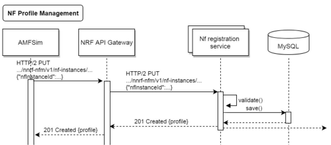
Figure 37. NF profile registration in NRF call flow
Procedure: Simulating an NF as SMF or AMF, an HTTP2 PUT request is sent to NRF with the NF profile to be registered.
Expected result: A 201 answer, indicating that registration is successful. Also, when registered profiles are checked in NRF using the REST API to display detailed profile information, the response returns the same information as was sent in the request.
NF profile discovery
Objective: Discovery of NF profiles registered by NFs in NRF.
The following figure shows the call flow:
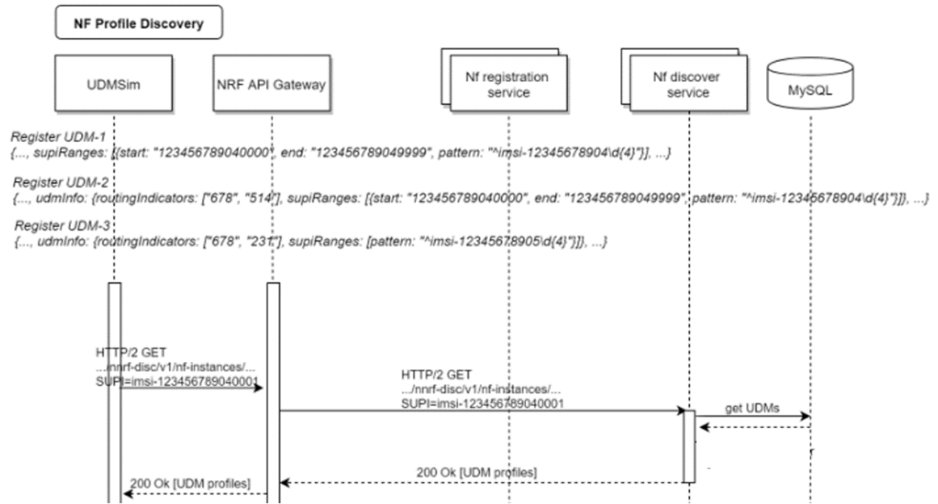
Figure 38. NF profiles in NRF discovery call flow
Procedure: One or more NF profiles is registered, including a real (nonsimulated) NF such as PCF, and an HTTP2 GET request requesting a registered NF profile is sent from a simulated NF to NRF.
Expected result: A 200 response, including the profile information of the NF that was registered in NRF.
PCF/BSF use cases
This section describes the objective, procedure, and expected results for PCF/BSF use cases.
SM session establishment
Objective: Create a session in PCF simulating an SMF. PCF will select a policy based on information in the request and the policy configuration in PCF.
The following figure shows the call flow:
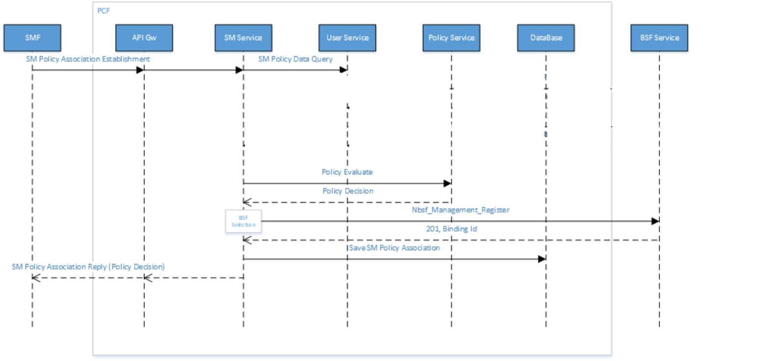
Figure 39. SM session establishment call flow
Procedure: A session establishment request is sent by the SMF simulator to PCF. Policies in PCF are selected based on the session information in the request and the conditions that are defined in the project. One rule is selected (it can be static or dynamic) and sent back to SMF.
Expected result: The selected rule in the response is based on information in the request and on conditions and actions that were configured in policy projects in PCF. The session should also be registered in BSF with PCF fqdn.
SM session update
Objective: Modify the SM session that you created with new parameters.
The following figure shows the call flow:
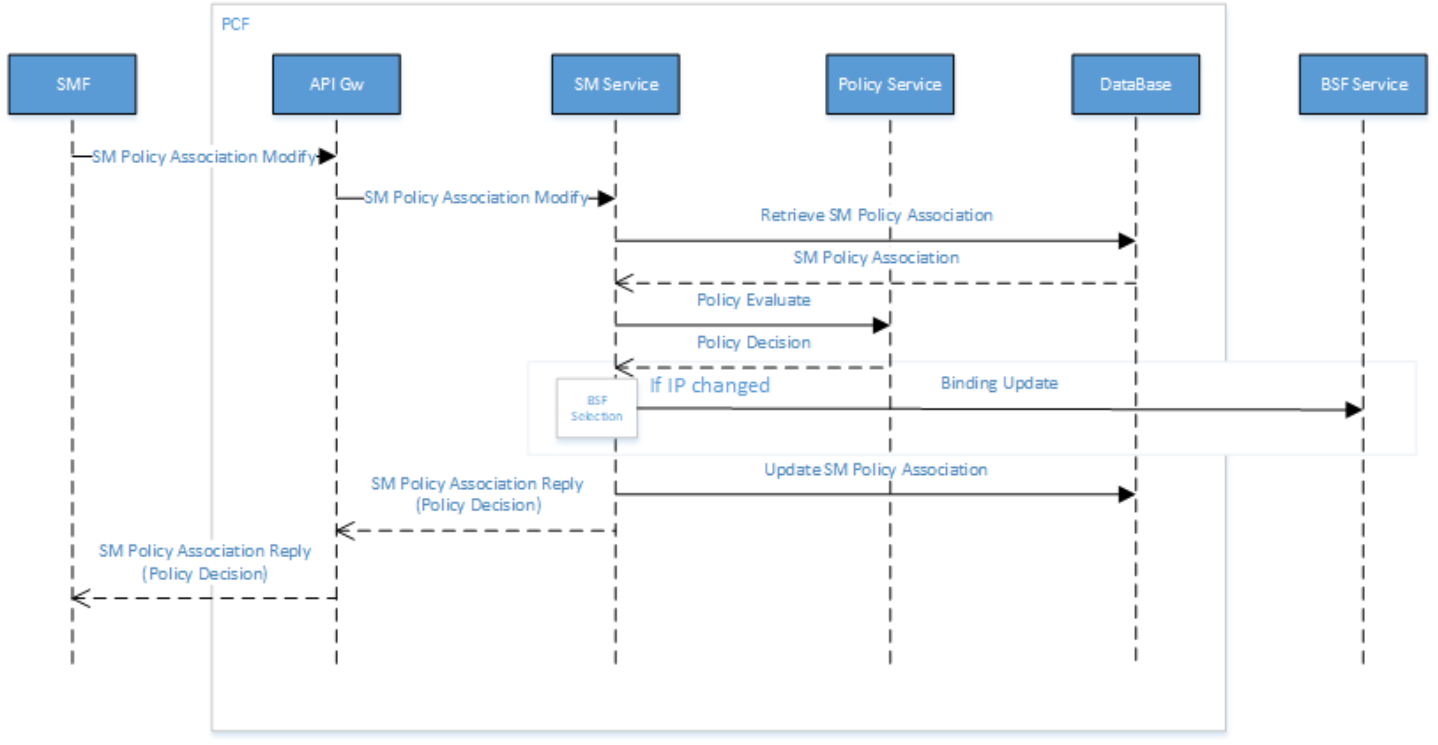
Figure 40. SM session update call flow
Procedure: An SM policy association modify request is sent by the SMF simulator to PCF with modified session information. SMF checks policies to select a new rule if applicable for the new information.
Expected result: Correct rule information is sent in response from PCF based on the information received and the conditions and action that are configured in the policy. Also, if there is an IP change, binding information is updated in BSF.
SM session termination
Objective: Terminate the SM session that you previously created and updated.
The following figure shows the call flow:
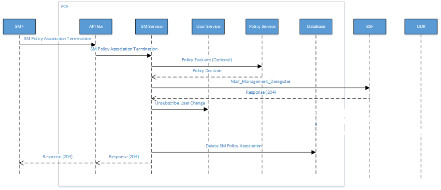
Figure 41. SM session termination call flow
Procedure: A session termination request with the session ID of the session that you previously created is sent from the SMF simulator to PCF.
Expected result: A 204 response from PCF. Confirm that the session was deleted in the UI of PCF and BSF.
AM session establishment
Objective: Create an AM session in PCF from the AMF simulator and select a rule based on information in the request.
The following figure shows the call flow:
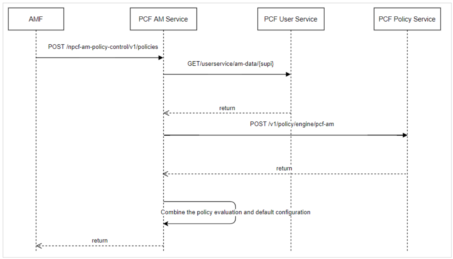
Figure 42. AM session establishment call flow
Procedure: A request to PCF including access network information is sent from the AMF simulator. The AM policy project has been configured so that PCF selects a rule according to the information received and returns the rule in the response message.
Expected result: The expected rule is received in the response message from PCF based on the access network information in the request. You can also verify the session creation in the PCF session viewer in the UI.
NSSF use cases
This section describes the objective, procedure, and expected results for NSSF use cases.
Not permitted S-NSSAI sent from UE
Objective: To test that the validation of the S-NSSAI that is requested by the UE was received from AMF.
The following figure shows the call flow:
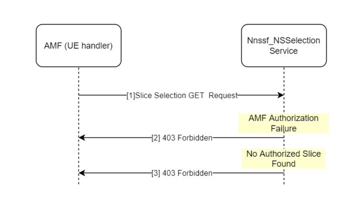
Figure 43. S-NSSAI test call flow
Procedure: No authorized S-NSSAIs are included in the request from AMF (a simulated AMF is used in the first phase).
Expected result: Because no S-NSSAIs are allowed in accordance with the policy configuration, NSSF returns a “403 Forbidden” response.
Initial registration to the 5GS without AMF redirection
Objective: To simulate an initial registration of UE where the selected target AMF is the same as the initial AMF.
The following figure shows the call flow:
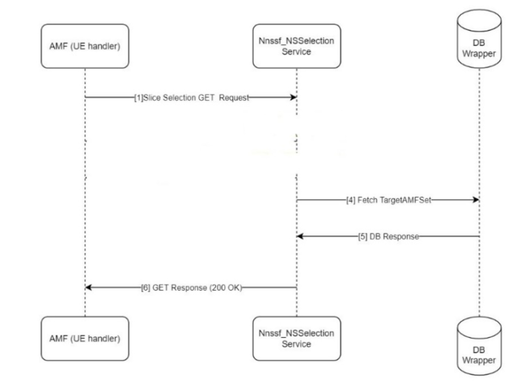
Figure 44. Initial UE registration
Procedure: An initial slice selection request is sent by the AMF simulator to NSSF. In accordance with the policy configured in NSSF, the target AMF selected is the same as the original AMF.
Expected result: A 200 OK response from NSSF containing the selected AMF information (here, the original AMF information).
Permitted S-NSSAI sent from UE
Objective: To test the NSSF feature to validate the S-NSSAI that is requested by UE and received from AMF.
The following figure shows the call flow:
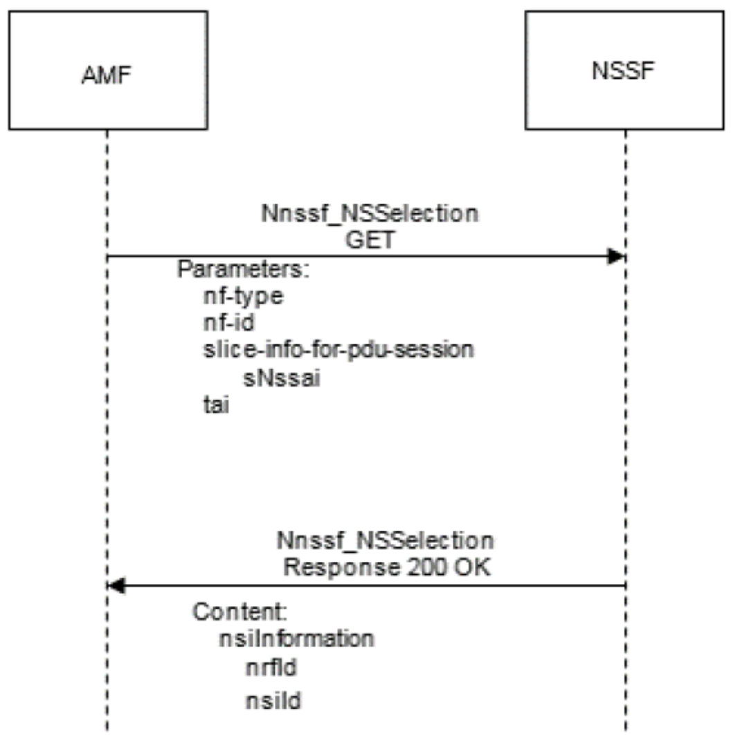
Figure 45. S-NSSAI from UE test call flow
Procedure: The AMF queries the NSSF with the specific S-NSSAI, the NF type of the NF service consumer, the requester ID, the PLMN ID of the SUPI, and the location information.
Expected result: The NSSF determines and returns the appropriate NRF to be used to select NF services within the selected network slice instance. The NSSF may also return an NSI ID identifying the network slice instance to use for this S-NSSAI.
Subscribe Service Operation
Objective: To test the NSSF availability service feature that validates the subscribe operation used by an NF service consumer (AMF) to get notifications for any change in NSSAI availability information.
The following figure shows the call flow:
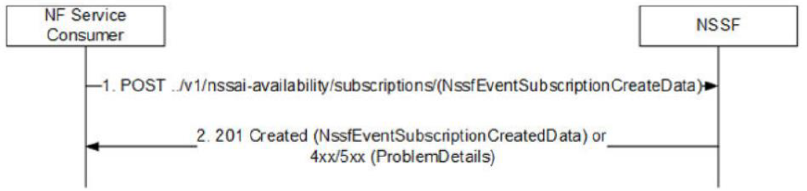
Figure 46. Subscribe service test call flow
Procedure: AMF sends a to NSSF with a notification URL and a list of tracking area IDs (TAIs) as the JSON body.
Expected result: NSSF stores the subscription request and responds with the list of allowed S-NSSAIs per TAI in the request. NSSF also returns a subscription-id and an expiry date. The expiry date reflects the duration up to which NSSF sends notifications for any change in the grant status of S-NSSAIs for subscribed TAIs.
SCP use cases
This section describes the objective, the procedure, and the expected results for SCP use cases.
SCP indirect communication - 3GPP Rel-16 Model C
Objective: To route a request from a service consumer NF (such as a simulated SMF) to a service producer NF (such as a PCF) indirectly through SCP using the 3gpp-Sbi-Target-Apiroot custom http header.
The following figure shows the call flow:
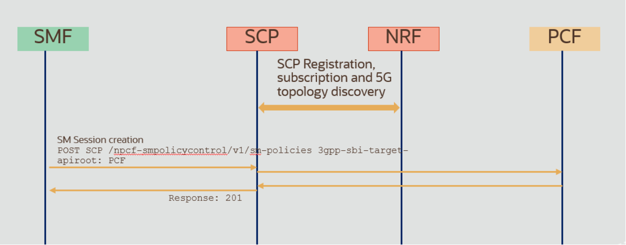
Figure 47. SCP indirect communication call flow
Procedure: After a successful registering of SCP and PCF to NRF, a request is sent from the SMF simulator to SCP that includes the 3gpp-sbi-target API root that defines the target as PCF fqdn. Because SCP previously registered to NRF and discovered the network topology, it will use information in 3gpp-sbi-target to route the request to PCF. PCF will send the response through SCP.
Expected result: Request and response are routed successfully through SCP. Confirm the successful routing by checking the response and the log and trace files in SCP and PCF.
Load balancing
Objective: Test the signaling load-balancing feature between two service producer NFs (such as PCF) originating from the service consumer (SMF simulator).
The following figure shows the call flow:
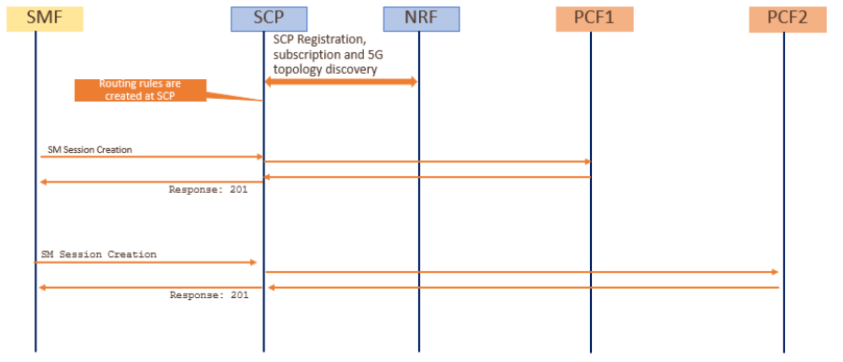
Figure 48. Load-balancing test call flow
Procedure: Signaling traffic is generated using the SMF simulator and sent to SCP. Routing rules that have been configured in SCP are applied, and requests that are received are forwarded to both PCFs according to the rules (percentage).
Expected result: Confirmation using log files or observability tools that traffic is balanced to both PCFs as defined in configured routing rules in SCP.
Alternate routing producer failure
Objective: To test the SCP feature of selecting an alternate route to a secondary producer in case a higher priority producer fails.
The following figure shows the call flow:
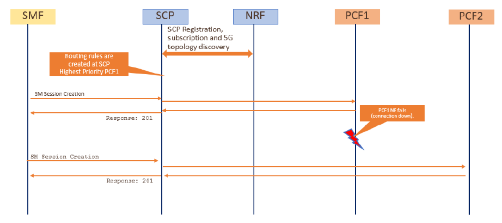
Figure 49. Alternate routing call flow
Procedure: When routing rules are configured in SCP, PCF1 has the highest priority. In normal conditions, all traffic is to be routed towards PCF1. A failure in PCF1 is simulated so that SCP selects the next lower priority NF producer of the same type (in this case, PCF2) to route traffic.
Expected result: If two PCFs are running, signaling traffic is routed to PCF1. After simulation of PCF1 failure, traffic is rerouted to PCF2. Verify the rerouting by using log files and observability tools.