
The following figure shows a typical Layer 3 leaf and spine Clos architecture using BGP EVPN VXLAN. The test setup consists of:
- Two spine switches—Z9432F-ON
- Six leaf switches—S5248F-ON
- Two external routers
- Nine hosts allocated as:
- Six servers
- Three VxRail appliances
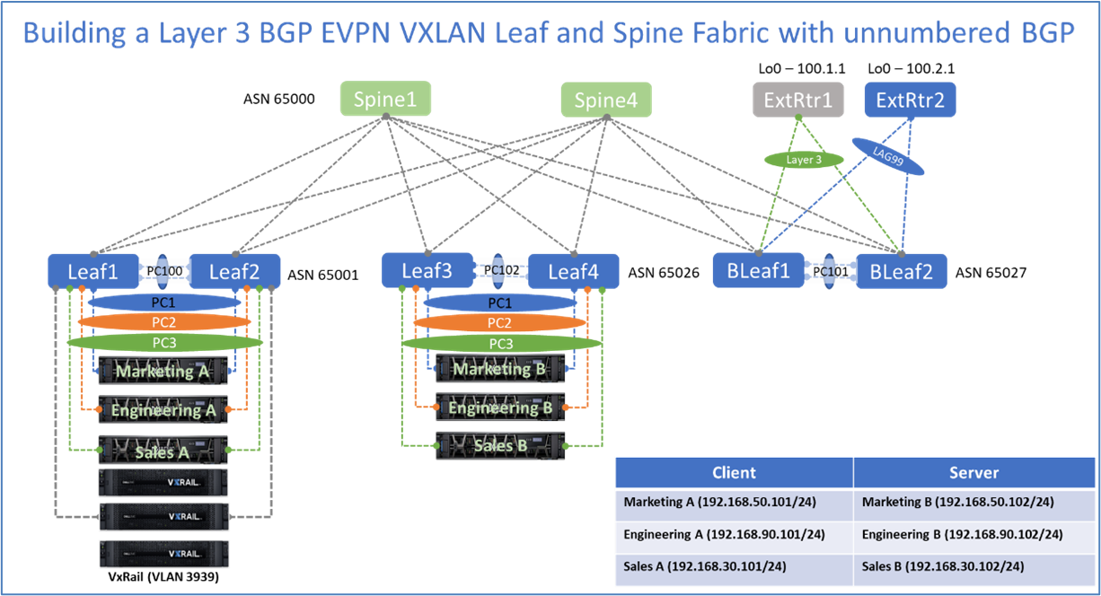
The workloads are separated into client and server functions.
The first leaf switch pair (Leaf1 and Leaf2) is connected to server A group and the VxRail cluster workloads. The second leaf switch pair (Leaf3 and Leaf4) is connected to the server B group workloads.
The border leaf pair is connected to two different external routers with different types of uplinks to demonstrate different configuration options.
This document is divided into Layer 2 and Layer 3 components and their configurations.
| Source Device | Switchport | Destination Device |
| Leaf1 | Ethernet 1/1 | Leaf2 |
| Leaf1 | Ethernet 1/2 | Leaf2 |
| Leaf1 | Ethernet 1/3 | Spine1 |
| Leaf1 | Ethernet 1/4 | Spine2 |
| Leaf1 | Ethernet 1/5 | Marketing |
| Leaf1 | Ethernet 1/6 | Engineering |
| Leaf1 | Ethernet 1/7 | Sales |
| Leaf1 | Ethernet 1/8 | VxRail Node1 |
| Leaf1 | Ethernet 1/9 | VxRail Node2 |
| Leaf1 | Ethernet 1/10 | VxRail Node3 |
| BLeaf1 | Ethernet 1/1 | BLeaf2 |
| BLeaf1 | Ethernet 1/2 | BLeaf2 |
| BLeaf1 | Ethernet 1/5 | Spine1 |
| BLeaf1 | Ethernet 1/6 | ExtRtr1 |
| BLeaf1 | Ethernet 1/7 | ExrRtr2 |