
Deployment
Deployment
-
After you have racked the system, a single PowerStore X model appliance requires simple network cabling to the physical Ethernet switches. Complete the cabling and apply the proper switch configuration to support management and data traffic from the appliance. Finally, connect the power cables and power on the appliance. After the PowerStore system is online, launch the Initial Configuration Wizard and configure the system.
The Initial Configuration Wizard is an HTML5-based configuration wizard that is hosted on the appliance. PowerStore T model appliances also use the same wizard with slight modifications. The Initial Configuration Wizard gathers all necessary information about networking, infrastructure services, and hypervisor details. The appliance automatically applies this configuration and brings PowerStore into a configured, operational state.
As of PowerStoreOS 3.2, multi-appliance clustering of PowerStore X model appliances is not supported. For details about configuring a multi-appliance PowerStore cluster, adding an appliance to an existing cluster, or removing an appliance, see the white paper Dell PowerStore: Clustering and High Availability.
For general information about PowerStore deployment and configuration, see the PowerStore: Quick Start Guide. This guide contains an overview of PowerStore deployment and directs readers to all other necessary documentation and resources for a successful installation.
Networking and cabling
PowerStore X model appliances require two physical Ethernet switches with Layer 2 connectivity. The Ethernet switches ensure high availability for iSCSI, management, replication, external storage import, and VMware vSphere vMotion traffic. Properly configuring and cabling to the physical Ethernet switches ensures that PowerStore features are ready for use when the Initial Configuration is complete.
To ensure that the Ethernet switches can provide high availability to PowerStore, configure them with one of the following Layer 2 interconnect options:
- Multi-chassis Link Aggregation Group (for example, Virtual Link Trunking, Virtual Port Channel, or Multi-Chassis Trunking)
- Reliable L2 uplinks
- Direct Trunk Link
Ensure that you meet the minimum cabling requirements listed in the following table.
Table 11. Minimum cabling requirements for PowerStore X models
PowerStore connection
Switch connection
Node A port 0 of 4-port card embedded module
Physical Ethernet switch 1
Node A port 1 of 4-port card embedded module
Physical Ethernet switch 2
Node B port 0 of 4-port card embedded module
Physical Ethernet switch 2
Node B port 1 of 4-port card embedded module
Physical Ethernet switch 1
The following figure outlines the minimum cabling that is required for PowerStore X model appliances.
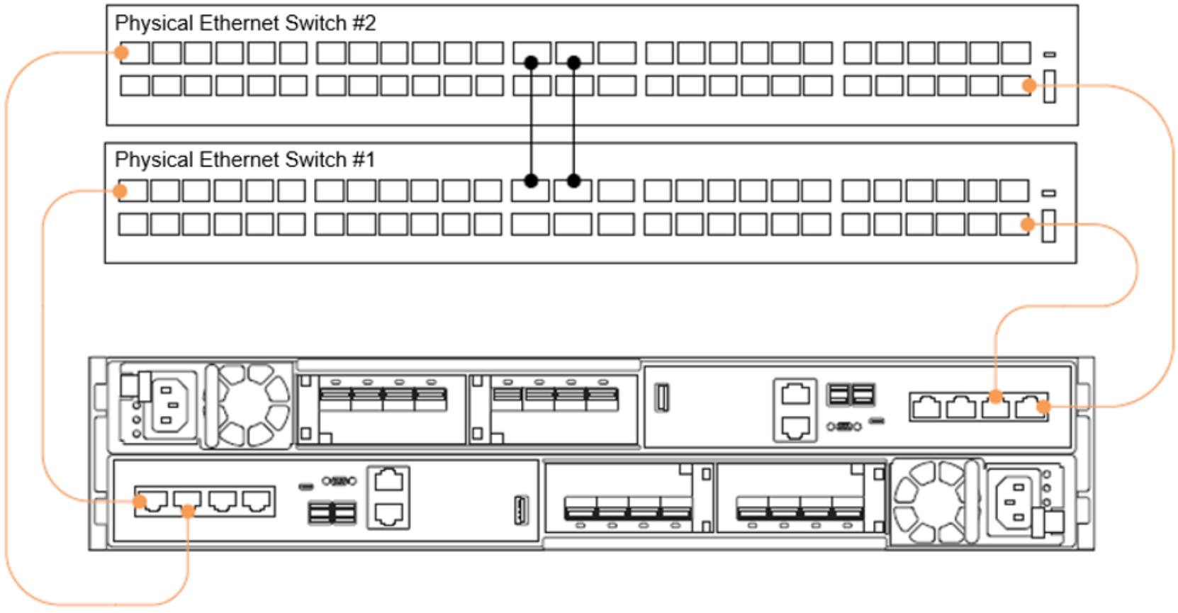
Figure 39. PowerStore X model minimum cabling
This cabling configuration ensures high availability and optimal traffic shaping for the PowerStore X model appliance. For more details about configuring the necessary switches, see the document PowerStore: Networking Guide for PowerStore X Models.
Discovery
After you cable the PowerStore system and configure the appropriate network settings, perform discovery and initial configuration for PowerStore.
Three discovery options are available:
- Physically connect a workstation to the appliance service port
- Go to the static discovery IP
- Discover the appliance remotely using the PowerStore Discovery Tool application
After the PowerStore system is discovered, step through the HTML5-based Initial Configuration Wizard to complete configuration.
Service port
The preferred method for configuration is to physically connect a workstation to the service port on node B of the PowerStore appliance. A static IP of 128.221.1.249 and subnet mask 255.255.255.0 is set on the workstation. You can log in to PowerStore and begin the Initial Configuration Wizard by directing a browser to 128.221.1.251. PowerStore X systems running on versions before PowerStoreOS 3.2 require connecting to the node A service port and directing the browser to 128.221.1.250.

Figure 40. PowerStore Direct Connect Discovery
Static IP
Another discovery method is available with the PowerStoreOS 1.0.3 release: through a static IP address.
You can access a range of IP addresses to discover the PowerStore and go through the initial configuration.
Perform the following steps:
- Discover PowerStore using any of the following IP addresses:
- https://169.254.0.10
- https://169.254.0.20
- https://169.254.0.30
- https://169.254.0.40
- https://169.254.0.50
- Connect the user workstation (laptop or virtual machine) through an Ethernet cable to the same network (either same switch or same untagged/native VLAN).
- Ensure that the user workstation has a static IP set in the same 169.254.0.x/16 subnet (for example, 169.254.0.100).
- Open a browser with one of the IP addresses previously listed and start the Initial Configuration wizard.
For more information about static IP address discovery, see the document Networking Guide for PowerStore X Models on Dell.com/powerstoredocs.
PowerStore Discovery Tool
If you cannot directly connect a workstation to the PowerStore appliance or through a static IP, download the PowerStore Discovery Utility from Dell Support and install it on a remote machine. The PowerStore Discovery Utility uses zero-configuration technology to detect the PowerStore system’s Avahi broadcasts. The PowerStore X system sends Avahi broadcasts from the 4-port card ports 0 and 1 on the native VLAN. The broadcasts require the remote machine to have an interface on the same network to detect the PowerStore system. The PowerStore Discovery Utility detects all unconfigured and configured PowerStore systems on the network. The utility automatically launches a web browser to the appliance to begin the Initial Configuration Wizard.
For more information about discovering and configuring PowerStore, see the document PowerStore: Quick Start Guide.
Initial configuration
Three networks are required to configure a PowerStore X model appliance. Each network requires several IP addresses, along with gateway, netmask, and VLAN information. If the network uses the access or native VLAN on the switch, VLAN 0 is used in the Initial Configuration Wizard. While networks can share the same VLAN, the management and storage network must be on different subnets. The following table details the specific IP requirements for each network.
Table 12. PowerStore X Initial Configuration Wizard, IP requirements
Network
Number of IP addresses
Purpose
Management
6
- Cluster IP
- Appliance IP
- 2 x controller VM IP
- 2 x ESXi IP
Storage
6 required, 9 for best performance
- 2 x iSCSI target IP, 4 x for best performance
- 4 x iSCSI initiator IP
- Global Storage Discovery IP (optional)
vMotion
2
2 x vMotion IP
Besides the networking information, you must have the following details to complete the Initial Configuration Wizard:
- DNS servers
- NTP servers
- vCenter IP
- vCenter administrator credentials
- PowerStore credentials
When you configure the system, the storage network provides iSCSI targets to support external iSCSI, data import, and replication traffic. The storage network IP addresses also provide internal iSCSI connectivity between the PowerStore controller VM and then PowerStore ESXi host. The four iSCSI initiators allow the ESXi hosts to establish an iSCSI data path to the controller VM iSCSI target.
Starting with PowerStoreOS 1.0.3, an optimization step is included in the Initial Configuration Wizard. This step requests two additional storage network IP addresses, which are automatically configured as iSCSI targets. These optional targets allow the ESXi hosts to have extra paths to the controller VM and improve performance. If you run a PowerStoreOS version earlier than version 1.0.3, follow the PowerStore: PowerStore X Performance Best Practice Tuning Knowledge Base article to add the additional storage network IPs and complete the configuration.
For more information about the Initial Configuration Wizard, see the document PowerStore: Networking Guide for PowerStore X Models or the white paper PowerStore Manager Overview.
When the Initial Configuration begins, several different tasks are automated from a vSphere perspective. The resources can be automatically deployed into an existing data center. Otherwise, a new resource is created that is based on configuration settings that are specified in the Initial Configuration Wizard. The two ESXi hosts of the PowerStore X model are joined to the target vCenter as a new ESXi cluster. A Distributed Virtual Switch is created for that ESXi cluster to join the two PowerStore nodes from a networking perspective. A default vVol datastore is mounted and reflects the usable capacity of the appliance. Finally, vSphere HA is configured on the ESXi cluster of the PowerStore X model.