
Deployment
Deployment
-
After you rack the system, a single PowerStore T model appliance requires simple network cabling to the physical Ethernet and management switches. Complete the cabling, and apply the proper switch configuration to support management and data traffic from the appliance. Finally, connect the power cables and power on the appliance. After the PowerStore system is online, launch the Initial Configuration Wizard and configure the system.
The Initial Configuration Wizard is an HTML5-based configuration wizard that is hosted on the appliance. PowerStore X model appliances also use the same wizard with slight modifications. The Initial Configuration Wizard gathers all necessary information about networking and infrastructure services. The appliance automatically applies this configuration and brings PowerStore into a configured, operational state.
For details about configuring a multi-appliance PowerStore T cluster, adding a PowerStore T model appliance to an existing cluster, or removing an appliance, see the document PowerStore: Clustering and High Availability.
For details about PowerStore deployment and configuration in general, see the PowerStore: Quick Start Guide. This document contains an overview of PowerStore deployment and directs readers to all necessary documentation and resources for a successful installation.
Networking and cabling
PowerStore T model appliances require two physical Ethernet switches with Layer 2 connectivity and at least one management switch. The Ethernet switches ensure high availability for iSCSI, NAS, replication, external storage import, data migration, and intra-cluster traffic. Properly configuring and cabling to the physical Ethernet switches ensures that all capabilities of PowerStore are ready for use when the Initial Configuration is complete.
To ensure that the Ethernet switches can provide high availability to PowerStore, configure them with one of the following Layer 2 interconnect options:
- Multi-chassis Link Aggregation Group (for example, Virtual Link Trunking, Virtual Port Channel, or Multi-Chassis Trunking)
- Reliable L2 uplinks
- Direct Trunk Link
The following table lists the minimum cabling requirements.
Table 8. Minimum cabling requirements for PowerStore T models
PowerStore connection
Switch connection
Node A port 0 of 4-port card embedded module
Physical Ethernet switch 1
Node A port 1 of 4-port card embedded module
Physical Ethernet switch 2
Node B port 0 of 4-port card embedded module
Physical Ethernet switch 2
Node B port 1 of 4-port card embedded module
Physical Ethernet switch 1
Node A 1 GbE management port
Management switch
Node B 1 GbE management port
Management switch
Starting with PowerStoreOS 2.0, single-appliance PowerStore T systems can complete initial configuration with only the management switch connection. This requirement simplifies PowerStore installation and reduces dependencies for the initial configuration. Systems that use file, iSCSI, external storage import, or clustering capabilities are not required to be properly configured and cabled to the physical Ethernet switches after initial configuration. The following table lists the minimum cabling requirements for systems that fit these criteria.
Table 9. Minimum cabling requirements for PowerStore T models running PowerStoreOS 2.0
PowerStore connection
Switch connection
Node A 1 GbE management port
Management switch
Node B 1 GbE management port
Management switch
Figure 35 outlines the minimum cabling that is required for PowerStore T appliances. Systems running PowerStoreOS 2.0 only require cabling to the management switch to complete the initial configuration.
This cabling configuration ensures high availability and optimal traffic shaping for the PowerStore T model appliance. For more details about configuring the necessary switches, see the document PowerStore: Networking Guide for PowerStore T Models.
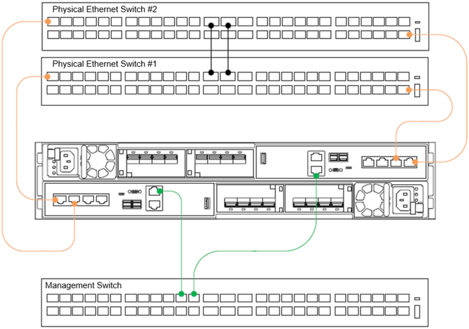
Figure 35. PowerStore T model appliance minimum cabling
PowerStore T model appliances contain a system bond by default on the first two ports of the embedded module 4-port card, as shown in Figure 36. PowerStore 500 model appliances that are ordered without a 4-port card do not contain a system bond. This bond provides high availability and potentially increased throughput for iSCSI, file, replication, external storage import, data migration, and intra-cluster traffic. If a link aggregation is not created across the two physical Ethernet switches for this bond, the bond automatically enters an active/passive state. One of the two ports is active for all traffic across the system bond. The passive port remains on standby if the active port experiences a network failure. This configuration is fully supported and delivers high availability during a network issue. If link aggregation is created across the two physical Ethernet switches for this bond, the bond automatically enters an active/active state. This configuration delivers high availability and increased throughput since both physical ports are active.
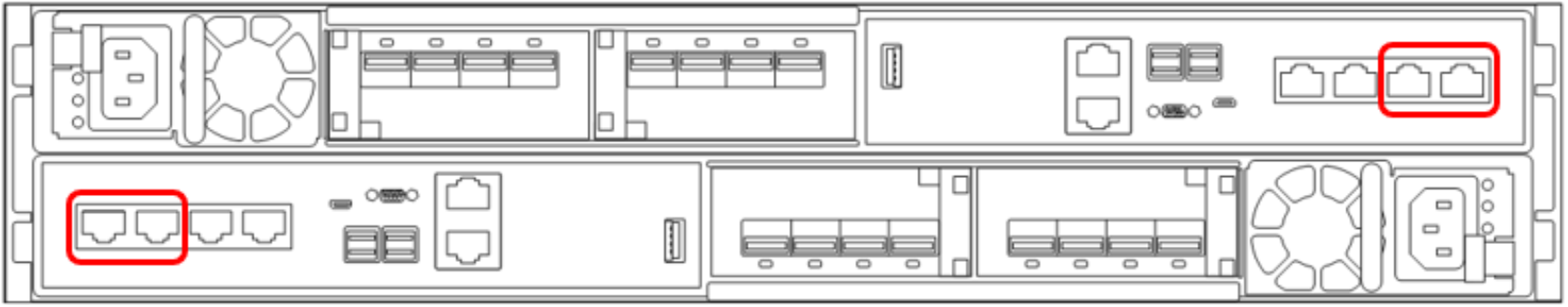
Figure 36. PowerStore T model system bonds
Discovery
After you cable the PowerStore system and configure the appropriate network settings, perform discovery and initial configuration for PowerStore.
Three discovery options are available:
- Physically connect a workstation to the appliance service port
- Go to the static discovery IP
- Discover the appliance remotely using the PowerStore Discovery Tool application
After the PowerStore system is discovered, step through the HTML5-based Initial Configuration Wizard to complete the configuration.
Service port
The preferred method for configuration is to physically connect a workstation to the service port on node B of the PowerStore appliance. A static IP of 128.221.1.249 and subnet mask 255.255.255.0 is set on the workstation. You can log in to PowerStore and begin the Initial Configuration Wizard by directing a browser to 128.221.1.251. PowerStore T systems running on versions before PowerStoreOS 3.0 require a connection to the node A service port and directing the browser to 128.221.1.250.

Figure 37. PowerStore Direct Connect Discovery
Static IP
Another discovery method available with the PowerStoreOS 1.0.3 release is to use a static IP address. You can access a range of IP addresses to discover the PowerStore and go through the initial configuration.
Perform the following steps:
- Discover PowerStore using any of the following IP addresses:
- https://169.254.0.10
- https://169.254.0.20
- https://169.254.0.30
- https://169.254.0.40
- https://169.254.0.50
- Connect the user workstation (also laptop or virtual machine) through an Ethernet cable to the same network (either through the same switch or the same untagged or native VLAN).
- Ensure that the user workstation has a static IP set in the same 169.254.0.x/16 subnet (for example, 169.254.0.100).
- Open a browser with one of the IP addresses previously listed, and start the Initial Configuration wizard.
For more information about the static IP address discovery, see the document Networking Guide for PowerStore T Models on Dell.com/powerstoredocs.
PowerStore Discovery Tool
If you directly connect a workstation to the PowerStore, or using a static IP is not possible, download the PowerStore Discovery Utility from Dell Support and install it on a remote machine. The PowerStore Discovery Utility uses zero-configuration technology to detect the PowerStore system Avahi broadcasts. The Avahi broadcasts are sent from the PowerStore T model management port on the native VLAN. The broadcasts also require the remote machine to have an interface on the same network to detect the PowerStore system. The PowerStore Discovery Utility detects all unconfigured and configured PowerStore systems on the network. The utility automatically launches a web browser to the appliance to begin the Initial Configuration Wizard.
Initial configuration
PowerStore T model appliances use two distinct external networks. However, only the management network is required to configure a PowerStore T model appliance. Optionally, you can configure the storage network, which allows support for iSCSI, data import, and replication traffic, when the system is configured. To configure the storage network, a minimum of two IPs are required. If you skip the storage network configuration during the Initial Configuration Wizard, you can configure it at any point through PowerStore Manager. Starting with PowerStoreOS 2.0, the storage network has been removed entirely from the Initial Configuration Wizard to streamline installation. You can configure the storage network in PowerStore Manager after you complete the configuration.
Each network requires several IP addresses, along with gateway, netmask, and VLAN information. By default, PowerStore uses the access or native VLAN on the switch for network connectivity. If the switch is configured for a specific VLAN, a check box is available to modify the VLAN number during the Initial Configuration Wizard. While networks can share the same VLAN, the management and storage network must be on different subnets. The following table details the specific IP requirements for each network.
Table 10. PowerStore T model Initial Configuration Wizard, IP requirements
Network
Number of IP addresses
Purpose
Management
4
- Cluster IP
- Appliance IP
- 2 x node IP
Besides the networking information, the details for DNS servers and NTP servers are required to complete the Initial Configuration Wizard.
For more information about the Initial Configuration Wizard, see the document PowerStore: Networking Guide for PowerStore T Models or PowerStore Manager Overview.