
ObjectScale appliance networking
ObjectScale appliance networking
-
ObjectScale appliances use the Dell S5448F for the pair of back-end switches. Customers must supply the two front-end switches for the client accessible.
Back-end switches
Dell provides two 100 GbE S5448F back-end switches with two 400GbE VLT cables. These switches are referred to as the Fox (BE1) and Hound (BE2) switches. All iDRAC cables from nodes and all front-end switch management cable connections route to the Fox switch. The following figure provides a visual representation of how ports are intended to be used to enable ObjectScale appliance management traffic and diagnostic ports. These port allocations are standard across all implementations.
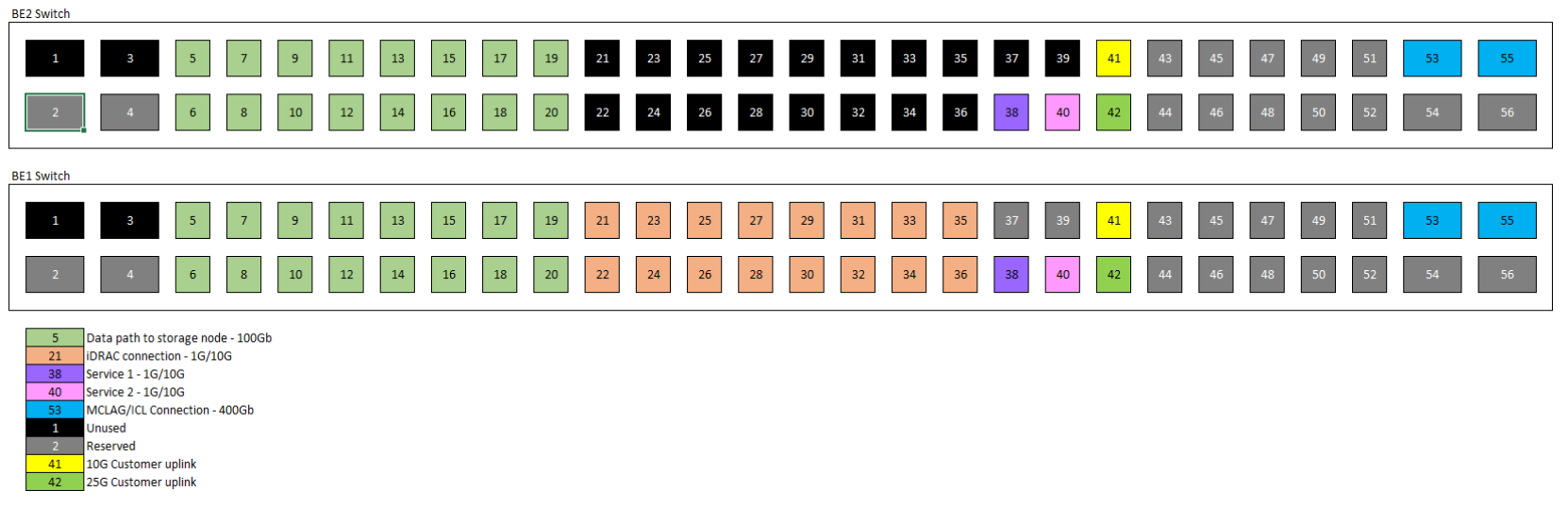
Figure 6. Back-end network switch port designation and usage
As a best practice, the two back-end switches should be configured in an aggregation by VLT and the network cards in the nodes should be configured as a bonded interface.

Figure 7. Back-end switch network architecture
Front-end switches
Customers must use their own front-end switches to connect to the ObjectScale appliance. Below are the recommendations:
- Use 25 GbE switches for optimal performance.
- For redundancy and to maintain a certain level of performance, have:
- Two physical switches configured in a multi-chassis aggregation (VLT, vPC, MLAG)
- Two uplinks per switch to customer switch, or four uplinks per rack minimum.
- Use dedicated switches for ObjectScale appliance. Do not use shared ports on the customer core network.
- LACP bond between storage nodes and the front-end switches.

Figure 8. Front-end switch network architecture
Load balancer
A load balancer is a device that acts as a reverse proxy and distributes network or application traffic across a number of nodes. Load balancers are used to increase capacity (concurrent users) and reliability of applications. They improve the overall performance of applications by decreasing the burden on servers associated with managing and maintaining application and network sessions, as well as by performing application-specific tasks.
MetalLB, the load-balancer implementation for a bare-metal Kubernetes cluster, offers a network load-balancer solution that integrates with standard network equipment in ObjectScale. ObjectScale appliance leverages layer 3 (BGP) mode by default for networking. All machines in the cluster establish BGP peering sessions with nearby routers that customers control, and instruct routers on how to forward traffic to the service IPs. Using BGP allows for true load balancing across multiple nodes and fine-grained traffic control, using BGP policy mechanisms. After packets arrive at the node, kube-proxy is responsible for the final traffic routing hop to move the packets to one specific pod in the service.
The exact behavior of the load balancing depends on the specific router model and configuration, but the common behavior is to balance per connection, based on TCP/UDP 5-tuple (source IP address, source port, destination IP address, destination port, transport protocol). Per-connection balancing means that all the packets for a single TCP or UDP session are directed to a single machine in the cluster. Traffic spreads only between different connections, and not for packets within one connection.
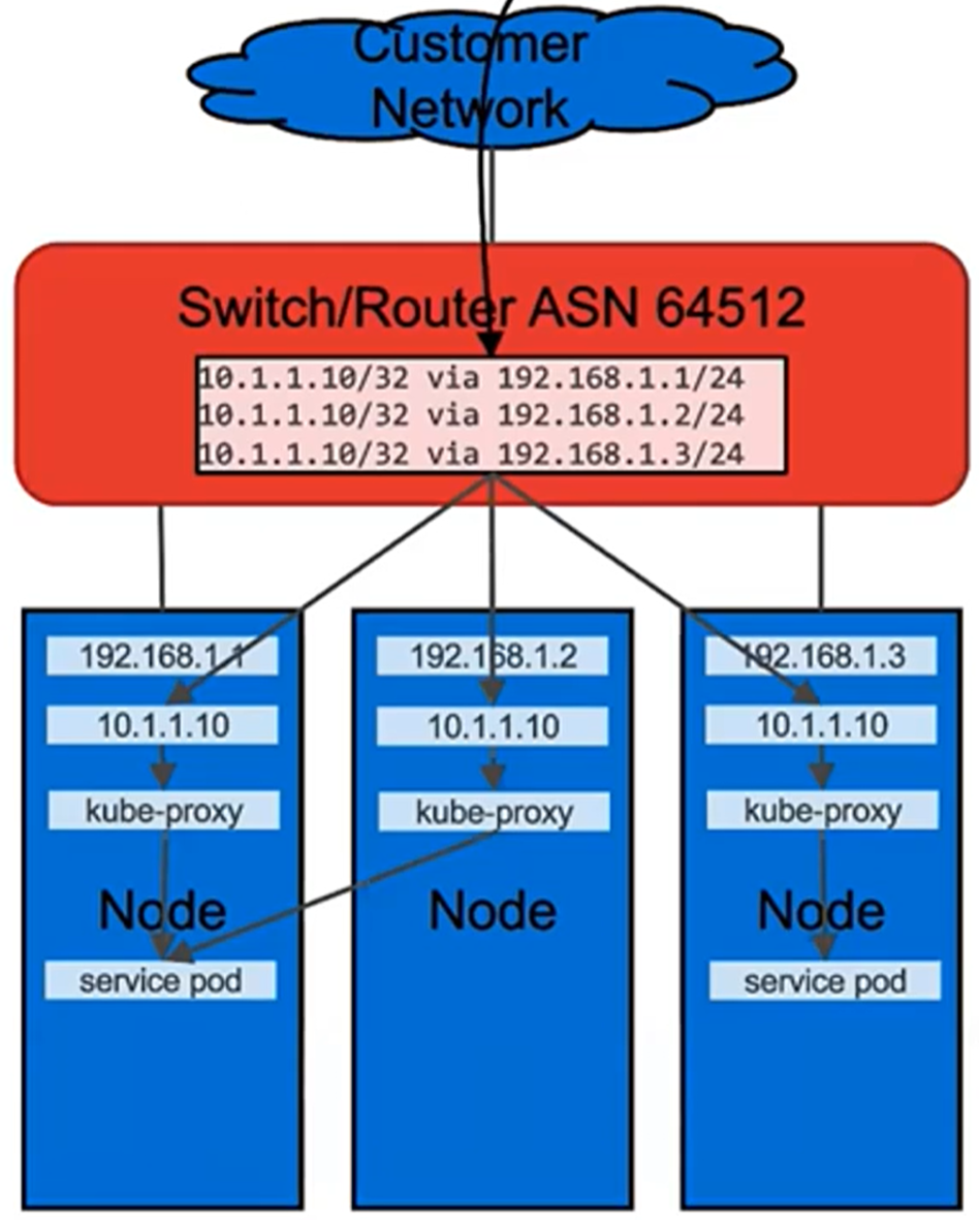
Figure 9. MetalLB Layer 3 (BGP) mode
Here is an example of the BGP configuration in front-end switches:
router bgp 64512
maximum-paths ibgp 128
router-id 192.168.10.250
!
Address-family ipv4 unicast
redistribute connected
redistribute static
!
neighbor 192.168.10.104
remote-as 64520
no shutdown
!
neighbor 192.168.10.105
remote-as 64520
no shutdown
!
For more information about the networking and cabling, see the Dell ObjectScale XF960 Hardware Guide.