Verify routing configuration in OMNI
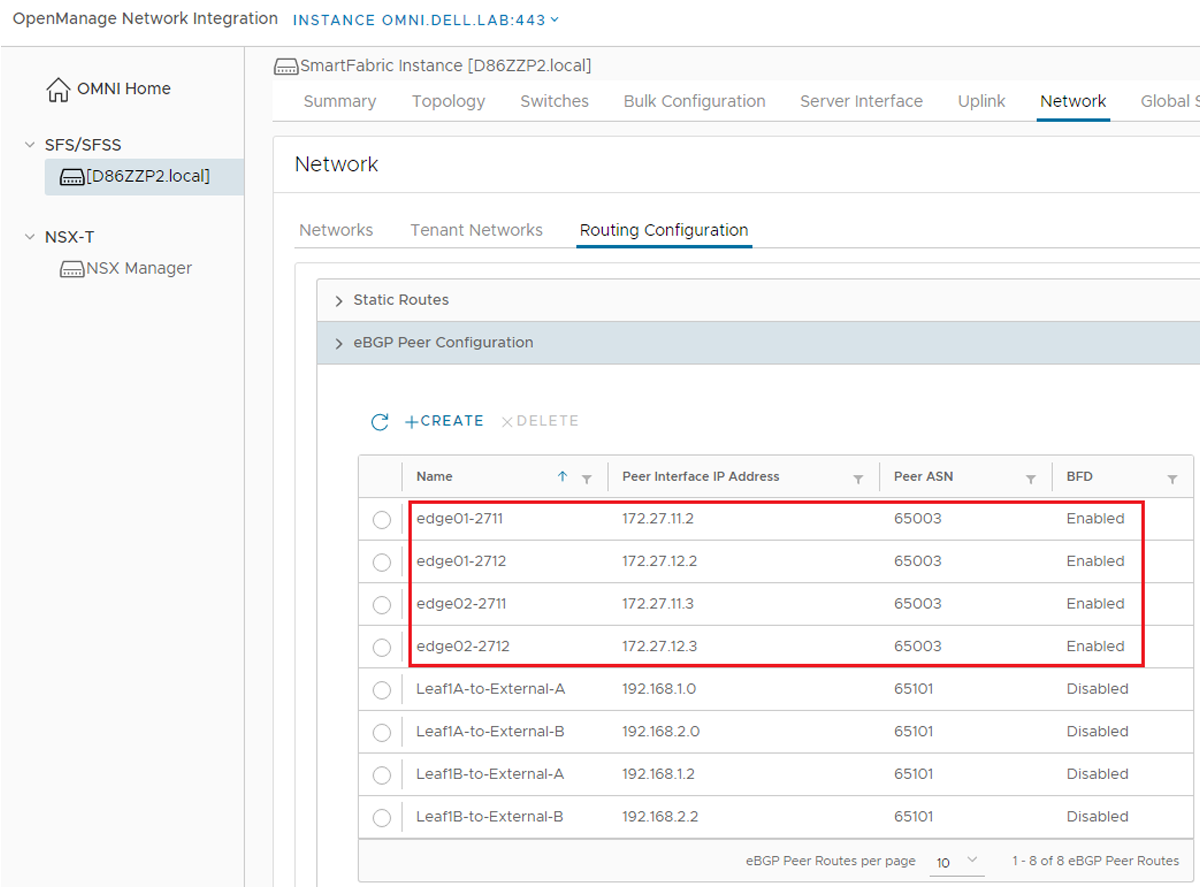
The routing configuration required for BGP peering from the NSX-T Edge nodes to the leaf switches is automated. OMNI reads the settings that were made in the Tier-0 router in NSX-T and makes the associated configurations on the SmartFabric switches.
This is verified in OMNI by selecting Network > Routing Configuration > eBGP Peer Configuration, and then selecting the routing submenu as shown in the figure below.
CLI validation
(Optional) The items configured in the preceding sections of this chapter in OMNI may be verified using the leaf switch CLI.
show vlan
The switch configuration may be verified at the CLI of the leaf switches with the show vlan command.
The three VxRail nodes in Rack 1 are connected to Eth1/1/1-1/1/3 in this example. The CLI output confirms all VxRail node connected ports are added to the NSX-T VLANs. The leafs in Rack 1 include the host overlay, VLAN 2500, the edge overlay, VLAN 2713, and the edge uplinks, VLANs 2711 and 2712. For the uplink networks, ports on Leaf1A are in VLAN 2711 and ports on Leaf 1B are in VLAN 2712 in this example.
Leaf1A# show vlanCodes: * - Default VLAN, M - Management VLAN, R - Remote Port Mirroring VLANs, @ - Attached to Virtual Network, P - Primary, C - Community, I - Isolate
Leaf1A# show vlan
 Codes: * - Default VLAN, M - Management VLAN, R - Remote Port Mirroring VLANs,
       @ - Attached to Virtual Network, P - Primary, C - Community, I - Isolated
 Q: A - Access (Untagged), T - Tagged
    NUM    Status    Description                     Q Ports
    2500   Active    vlan2500                        T Eth1/1/1-1/1/3
                                                     T Po1000
    2711   Active    vlan2711                        T Eth1/1/1-1/1/3
    2713   Active    vlan2713                        T Eth1/1/1-1/1/3
                                                     T Po1000
    4000   Active    vlan4000                        T Po96-97,1000
    4001   Active    vlan4001                        A Po96
    4002   Active    vlan4002                        A Po97
 *   4089   Active    vlan4089                        A Po1000
    4090   Active    vlan4090                        T Po1000
    4094   Active                                    T Po1000

Leaf1B# show vlan
 Codes: * - Default VLAN, M - Management VLAN, R - Remote Port Mirroring VLANs,
       @ - Attached to Virtual Network, P - Primary, C - Community, I - Isolated
 Q: A - Access (Untagged), T - Tagged
    NUM    Status    Description                     Q Ports
    2500   Active    vlan2500                        T Eth1/1/1-1/1/3
                                                     T Po1000
    2712   Active    vlan2712                        T Eth1/1/1-1/1/3
    2713   Active    vlan2713                        T Eth1/1/1-1/1/3
                                                     T Po1000
    4000   Active    vlan4000                        T Po96-97,1000
    4001   Active    vlan4001                        A Po96
    4002   Active    vlan4002                        A Po97
 *   4089   Active    vlan4089                        A Po1000
    4090   Active    vlan4090                        T Po1000
    4094   Active                                    T Po1000
Since there are no NSX Edges in Rack 2, the host overlay VLAN, VLAN 2500, is the only NSX-T VLAN applied to Leaf 2A and 2B. The VxRail node in Rack 2 is connected to Eth1/1/1 in this example.
The VxRail node in Rack 2 is connected to eth1/1/1 in this example.
Leaf2A# show vlan
 Codes: * - Default VLAN, M - Management VLAN, R - Remote Port Mirroring VLANs,
       @ - Attached to Virtual Network, P - Primary, C - Community, I - Isolated
 Q: A - Access (Untagged), T - Tagged
    NUM    Status    Description                     Q Ports
    2500   Active    vlan2500                        T Eth1/1/1
                                                     T Po1000
    4000   Active    vlan4000                        T Po100-101,1000
    4005   Active    vlan4005                        A Po100
    4006   Active    vlan4006                        A Po101
 *   4089   Active    vlan4089                        A Po1000
    4090   Active    vlan4090                        T Po1000
    4094   Active                                    T Po1000
show running configuration interface vlan vlan_id
The show running configuration interface vlan vlan_id command is used to confirm the IP addresses, virtual addresses, and IP helper address are properly configured on the leaf switches for the host overlay, edge overlay, and uplink VLANs.
The host overlay network, VLAN 2500 in this example, exists on all four leaf switches. Example output from Leaf1A is shown below. The output on Leaf1B is similar.
Leaf1A# show running-configuration interface vlan 2500
 !
 interface vlan2500
 description vlan2500
 no shutdown
 ip address 172.25.101.253/24
 ip helper-address 172.19.11.50
 no ip igmp snooping
 no ipv6 mld snooping
 !
 vrrp-group 2
  virtual-address 172.25.101.254
Example output from Leaf2A is shown below. The output on Leaf2B is similar.
Leaf2A# show running-configuration interface vlan 2500
 !
 interface vlan2500
 description vlan2500
 no shutdown
 ip address 172.25.102.253/24
 no ipv6 mld snooping
 no ip igmp snooping
 ip helper-address 172.19.11.50
 !
 vrrp-group 1
  virtual-address 172.25.102.254
The edge overlay network, VLAN 2713 in this example, is only on the border leaf switches in Rack 1. Example output from Leaf1A is shown below. The output on Leaf1B is similar.
Leaf1A# show running-configuration interface vlan 2713
 !
 interface vlan2713
 description vlan2713
 no shutdown
 ip address 172.27.13.252/24
 no ip igmp snooping
 no ipv6 mld snooping
 !
 vrrp-group 3
  virtual-address 172.27.13.254
The uplink networks are only on the border leaf switches in Rack 1. This is VLAN 2711 on Leaf1A and VLAN 2712 on Leaf1B.
Leaf1A# show running-configuration interface vlan 2711
 !
 interface vlan2711
 description vlan2711
 no shutdown
 ip address 172.27.11.1/24
 no ipv6 mld snooping
 no ip igmp snooping

Leaf1B# show running-configuration interface vlan 2712
 !
 interface vlan2712
 description vlan2712
 no shutdown
 ip address 172.27.12.1/24
 no ipv6 mld snooping
 no ip igmp snooping
show ip bgp summary
Run the show ip bgp summary command on the border leafs, Leaf1A and Leaf1B, to verify BGP is up between the leaf switches and the NSX Edge Tier-0 gateway. The Tier-0 gateway connections are underlined.
Leaf1A# show ip bgp summary
 BGP router identifier 172.16.128.0 local AS number 65011
 Neighbor          AS          MsgRcvd     MsgSent     Up/Down          State/Pfx
 172.16.0.0        65011       3439        3436        2d:01:22:55      28
 172.16.0.3        65012       3435        3450        2d:01:31:00      17
 172.16.0.7        65012       3435        3455        2d:01:31:00      17
 172.27.11.2       65003       429         489         00:27:19         6
 172.27.11.3       65003       398         463         00:26:09         6
 192.168.1.0       65101       3429        3439        2d:01:31:46      8
 192.168.2.0       65101       3431        3438        2d:01:31:46      8

Leaf1B# show ip bgp summary
 BGP router identifier 172.16.128.1 local AS number 65011
 Neighbor          AS          MsgRcvd     MsgSent     Up/Down        State/Pfx
 172.16.0.1        65011       3419        3432        2d:01:26:11    28
 172.16.0.5        65012       3422        3420        2d:01:25:36    28
 172.16.0.9        65012       3423        3436        2d:01:25:28    28
 172.27.12.2       65003       448         525         00:29:17       13
 172.27.12.3       65003       446         514         00:29:11       13
 192.168.1.2       65101       3416        3422        2d:01:26:09    8
 192.168.2.2       65101       3419        3415        2d:01:26:09    8
Verify BGP route propagation
To verify BGP has propagated routes from the Tier-1 gateway to the SmartFabric switches, run the show ip route command at the CLI of one of the leaf switches. The underlined output confirms the routes to the NSX-T tenant segments have been learned using BGP.
The following output is from Leaf1A. The command output from the other leafs and spines in the fabric will also have two routes to the tenant segments learned using BGP.
Leaf1A# show ip route
 Codes: C - connected
       S - static
       B - BGP, IN - internal BGP, EX - external BGP
       O - OSPF, IA - OSPF inter area, N1 - OSPF NSSA external type 1,
       N2 - OSPF NSSA external type 2, E1 - OSPF external type 1,
       E2 - OSPF external type 2, * - candidate default,
       + - summary route, > - non-active route
 Gateway of last resort is not set
  Destination           Gateway                                        Dist/Metric       Last Change
 -----------------------------------------------------------------------------------------
  B  EX 10.0.2.1/32     via 192.168.1.0                 20/0              3 days 18:33:56
  B  EX 10.0.2.2/32     via 192.168.2.0                 20/0              3 days 18:33:48
  B  EX 10.10.10.0/24   via 172.27.11.2                 20/0              3 days 18:33:21
                        via 172.27.11.3
  B  EX 10.10.20.0/24   via 172.27.11.2                 20/0              3 days 18:33:21
                        via 172.27.11.3
(output truncated)The external switches are configured in this deployment per Dell Networking SmartFabric Services Deployment with VxRail . The underlined output below confirms the external switches have learned the routes to the app and web networks using BGP from the SmartFabric switches.
The following output is from External-A. The command output on External-B will also have two routes to the tenant segments learned using BGP.
External-A# show ip route
 Codes: C - connected
       S - static
       B - BGP, IN - internal BGP, EX - external BGP
       O - OSPF, IA - OSPF inter area, N1 - OSPF NSSA external type 1,
       N2 - OSPF NSSA external type 2, E1 - OSPF external type 1,
       E2 - OSPF external type 2, * - candidate default,
       + - summary route, > - non-active route
 Gateway of last resort is not set
  Destination            Gateway                            Dist/Metric       Last Change
 -----------------------------------------------------------------------------------------
  C     10.0.2.1/32      via 10.0.2.1          loopback0    0/0          3 days 01:56:32
  B  IN 10.0.2.2/32      via 192.168.3.21           200/0        3 days 01:56:07
  B  EX 10.10.10.0/24    via 192.168.1.1                    20/0         21:04:21
                         via 192.168.1.3
  B  EX 10.10.20.0/24    via 192.168.1.1                    20/0         21:04:21
                         via 192.168.1.3
  B  EX 172.18.11.0/24   via 192.168.1.1                    20/0         2 days 21:58:01
                         via 192.168.1.3
  C     172.19.11.0/24   via 172.19.11.252     vlan1911     0/0          3 days 01:56:12

(output truncated)
NSX-T validation
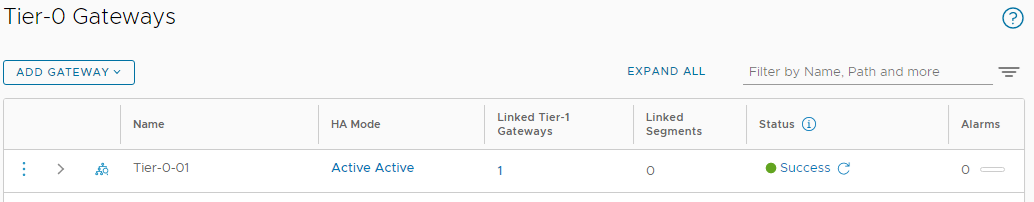
Tier-0 gateway
In NSX Manager, go to Networking > Tier 0 Gateways. Now that the leaf switches are configured, the Status of the Tier-0 gateway should indicate Success, and Alarms should be at 0, as shown.
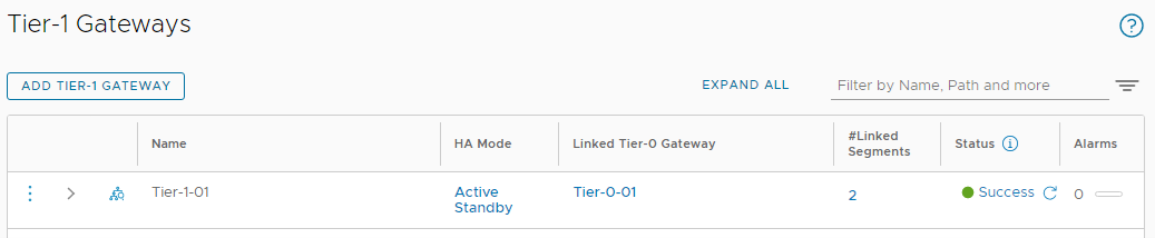
Tier-1 gateway
In NSX Manager, go to Networking > Tier 1 Gateways. The Status of the Tier-1 gateway should indicate Success, and Alarms should be at 0, as shown.