As data centers are being upgraded from less reliable Layer 2 networks to new and robust leaf-spine topologies, there are still applications that use Layer 2 networks. There is a growing concern to fit such a solution that expects Layer 2 connectivity in a network that has Layer 3 as its foundation.
Ethernet VPN (EVPN) solves this issue by building a virtual Layer 2 network overlay over the underlying Layer 3 network. It uses BGP as its control protocol.
EVPN is a developed technology used in service provider Multiprotocol Label Switching (MPLS) networks for some time. A variation of this technology is now being adopted in the data center world using Virtual Extensible LAN (VxLAN).
EVPN supports network virtualization and multitenancy which divides up a single physical network into many virtual networks. Virtualizing a physical network allows it to be shared between multiple tenants making efficient use of the network. The physical underlay network over which these virtual networks are transported is unaware that it is transporting multiple virtual overlay networks.
Besides Layer 2 and Layer 3 fabrics, the Dell Enterprise SONiC OS supports advanced deployment models or solutions that extend into overlays, multisite fabrics, and Telco use cases.
The following use cases highlight the capabilities of the operating system that bring unique value to our customers.
BGP EVPN VxLAN
As an enhancement and combination of the best of both fabrics (Layer 2 and Layer3), EVPN VxLAN is an overlay control plane technology for VxLAN.
It implements an overlay that permits the extension of a Layer 2 domain across a Layer 3 fabric where virtualization and multitenancy deployments leverage Layer 2 connectivity.
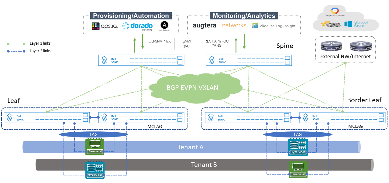
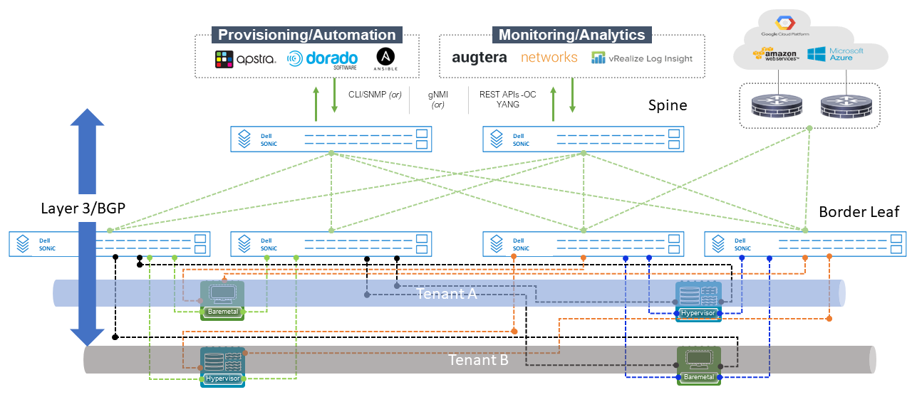
The figure below shows a BGP EVPN VxLAN fabric where Tenants A and B are being stretched across a Layer 3 fabric implemented by BGP.
The inter-switch (leaf to spine) links are Layer 3 while the downstream connections to the end-hosts are Layer 2. MC-LAG is implemented at the leaf switch layer to provide link redundancy to the end-hosts.
Virtual tunnel endpoints (VTEPs) are created on each leaf switch pair. These VTEPs establish the tunnels used by each tenant to create a Layer 2 connectivity across the Layer 3 fabric.
The border leaf switch pair connected to an external router or switch may or may not have workloads connected to them.
The links from the border leafs to the external routers are Layer 3 connections with a /31 subnet.
There are two VxLAN deployment models: Layer 2 VxLAN and Layer 3 VxLAN
In a Layer 2 VxLAN, all Layer 2 traffic is directed towards a single Layer 3 point. This Layer 3 point can be the edge or border leaf switches, or an external router or firewall connected to the edge or border leaf switches.
In a Layer 3 VxLAN, tenant VRFs, an anycast gateway, and a transport VNI are configured to provide cross tenant communication while maintaining a Layer 2 domain stretched across a Layer 3 fabric.
In a Layer 3 VxLAN deployment, two types of integrated bridging and routing (IRB) implementations are available:
In symmetric routing, all VTEPs can perform routing, and routing decisions are made on both ingress and egress VTEPs.
In asymmetric routing, all VTEPs can perform routing. Routing decisions are made only on ingress VTEPs. Egress VTEPs only perform bridging.
Figure 3. Dell Technologies SONiC and EVPN VxLAN fabric
Deployment best practices
Like all scalable high-performance fabrics where virtualization and multitenancy are key requirements, the following best practices are recommended:
Create a Layer 3/Layer 2 demarcation point. From the leaf layer to the spine layer, Layer 3 should be implemented, in this case, BGP EVPN VxLAN.
Any connections downstream from the leaf layer should be Layer 2.
Implement switch redundancy at the leaf layer with MC-LAG.
Symmetric IRB provides better scalability as each VTEP does not have to store information for each tenant VLAN in the routing table memory.
Asymmetric IRB is better suited for small and medium-sized data centers and for deployments where there is Layer 2 VxLAN (no tenant data traffic routing is needed) and Layer 3 VxLAN (multiple tenants can communicate with each other).
Broadcast, unknown unicast, and multicast traffic should be controlled whenever possible to avoid network performance degradation using the storm-control command.
For simplicity, unnumbered BGP should be configured between leaf and spine links.
Enable "neighbor suppression" on Layer 3 tenant VLANs to reduce ARP flooding in the overlay network.
Link state tracking should be enabled on the leaf and spine interlinks. Link state tracking helps to minimize traffic loss during a reset or loss of a switch in the fabric.
Enable "max-med on-startup" to allow BGP convergence to take place on the affected node (leaf or spine) before data traffic is allowed on the fabric.
Data Center Interconnect (DCI)
The ability to interconnect multiple EVPN fabrics is critical to the evolution of the Dell Enterprise SONiC networking operating system. With version 4.1, multiple EVPN fabrics that are geographically separated can now be interconnected.
In a DCI deployment, Layer 2 domains stretch across Performance Optimized Datacenters (PODs) while restricting the tunnels to each VTEP within the same site. Border gateways in each site create two types of tunnels, internal and external. The internal tunnel is created between local VTEPs for intrasite traffic, and an external tunnel with a remote site for intersite traffic.
There are several strategic benefits that DCI provides:
EVPN fabric expansion based on open standards
Legacy environment integration, with EVPN, the ability for virtual environments to reach or communicate with nonvirtualized applications is important. DCI allows these connections while maintaining the benefits of a virtualized environment.
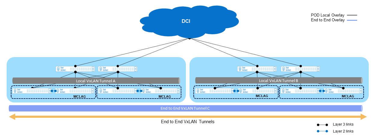
The following figure shows one of two DCI interconnects models. This model shows the interconnect originating at the spine layer. This model allows VxLAN tunnels to stretch across multiple PODs within same or different geographic locations.
The characteristics of this model are as follows:
Workload mobility across any POD
VxLAN EVPN control plane stretching across PODs
Sharing of Layer 4 - Layer 7 services across PODs
Recommended for active/active data center use cases
Figure 4. Dell Enterprise SONiC and Data Center Interconnect - Multi-POD
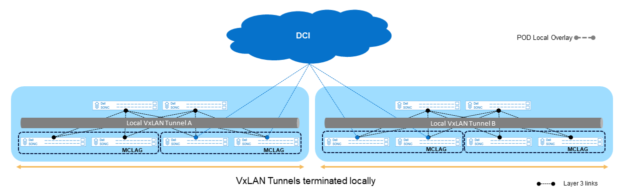
The second model in the following figure shows the interconnect originating at the leaf layer, or edge leaf switches. This model allows VxLAN tunnels to be terminated locally in each POD shown in gray. The tunnels do not exit the PODs unlike the previous model.
The characteristics of this model are as follows:
Each POD is a distinct Availability Zone (AZ), providing failure domain isolation.
Each POD runs a distinct Internal Gateway Protocol (IGP) and BGP-EVPN instance.
Optionally, Layer 2 domains can be stretched across PODs.
Recommended for active/backup data center use cases.
Note: Multisite DCI is available only in the Enterprise Standard and Premium bundles.
Figure 5. Dell Enterprise SONiC and Data Center Interconnect - Multifabric
Deployment best practices
Whenever deploying DCI, it is best to keep the following items in mind:
Whenever possible, always deploy multiple links from the source device towards the DCI cloud.
The links towards the DCI cloud are always Layer 3 connections.
Always try to summarize routes towards the DCI cloud.
Deploy MC-LAG on the edge or border leaf switches. The border leaf switches perform a critical intersite connection; therefore, redundancy is important.
Routing on the Host
Traditionally, network infrastructures have always had a clear demarcation zone between Layer 3 and Layer 2 switching.
In a traditional deployment model, any connection from the leaf towards the spine is Layer 3 and Layer 2 from the leaf to the end-host. This means all end-hosts that need to communicate with a different end-host in a different network need to have a Layer 3 gateway as a first hop.
In a combined switching environment, Layer 2 comes with performance and scaling limitations related to spanning-tree and the number of VLANs. To overcome these limitations, Layer 3 end-to-end should be deployed, however, this requires the end-hosts to be able to participate in the entire Layer 3 protocol stack.
Routing on the host was introduced with BGP unnumbered interface to achieve Layer 3 end-to-end and mitigate the performance and scaling limitations created by Layer 2 deployments. Routing on the host has the following key benefits:
VM mobility
Layer 3 control plane for VM discovery and reachability
Eliminates the need for leaf interconnect links
Layer 3 loop avoidance through Time to Live (TTL) implementation
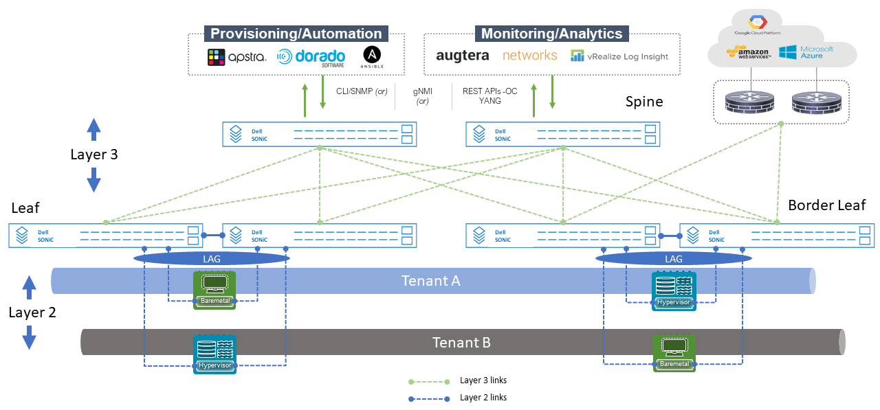
The following figure shows the typical Layer 3 and Layer 2 deployment where all end-hosts terminate their traffic at a Layer 3 gateway. This gateway can be configured at the leaf switches through a virtual switch interface with an IP address, or it can be configured at the spine switches. See Layer 2 fabric deployment for additional design methodology information.
The following figure shows routing on the host deployment where Layer 3 end-to-end is deployed including at the end-host. With this deployment insufficient number of VLANs, limited number of MAC addresses, or inefficient use of switch interlinks are removed.
Since Layer 3 is deployed end-to-end, the only limiting factor in this deployment is the route table size of the switch and the end-host's Layer 3 protocol stack support.
With Dell Enterprise SONiC, routing on the host is enabled by configuring BGP unnumbered on all the leaf and spine switch interfaces. The end-hosts running Layer 3 protocol stack advertise their own network dynamically to the directly connected leaf switches. This in turn transforms all end-hosts connections as single IP addresses that can move freely within and across the fabrics, i.e. mobility.
Another differentiator with routing on the host is the elimination of interconnect links between leaf switches that provide MC-LAG features. MC-LAG limits redundancy to two leaf switches at any given time. This creates a potential reduction performance by 50% if a leaf switch were to fail.
With routing on the host, the host can advertise and connect to all the leaf switches thereby providing full connectivity regardless of a link failure, and through equal cost multipath (ECMP) equal load sharing is achieved.
Figure 7. Dell Enterprise SONiC - Routing on the Host
Deployment best practices
Routing on the host leverages Layer 3 concepts and has similar Layer 3 deployment guidelines:
Routing on the host uses BGP. OSPF is not supported.
Configure /32 subnet on all end-hosts.
Connect end-host to all leaf switches to achieve full mesh connectivity.
Configure ECMP across all end hosts links towards the leaf switches.
Multitenant Bridging: Q-in-Q and VLAN Translation
SONiC was purpose built for the cloud environment where multitenancy is key. Dell Enterprise SONiC stays true to this offering by delivering Q-in-Q, one of the most user-friendly, and well-known service provider features where a service provider VLAN can be used to switch multiple end-user services.
Q-in-Q and VLAN translation allows cloud providers and service providers to support many customers or tenants inside a common fabric by isolating each tenant for security and manageability benefits.
With Q-in-Q, two VLAN IDs are used, a user or internal VLAN ID which carries a specific service and a service provider VLAN ID to switch or transmit the end-user data across the service or cloud provider network.
VLAN translation differs from Q-in-Q in that single or double tagged customer VLAN (C-VLAN) is swapped with a service provider VLAN (S-VLAN) at the ingress provider edge device. The customer traffic is then forwarded based on the service provider VLAN in the provider infrastructure.
To enable VLAN translation, VLAN stacking must be enabled first followed by a reboot on the following switches: Z9432F and S5448F. The configuration details can be found in the Dell Enterprise SONiC 4.1 Q-in-Q VLAN Tunneling chapter.
If VxLAN is used as an overlay with the service provider, the customer traffic is identified by a service provider (S-VLAN), this VLAN is then mapped to a VxLAN network identifier (VNI) and forwarded based on the VNI.
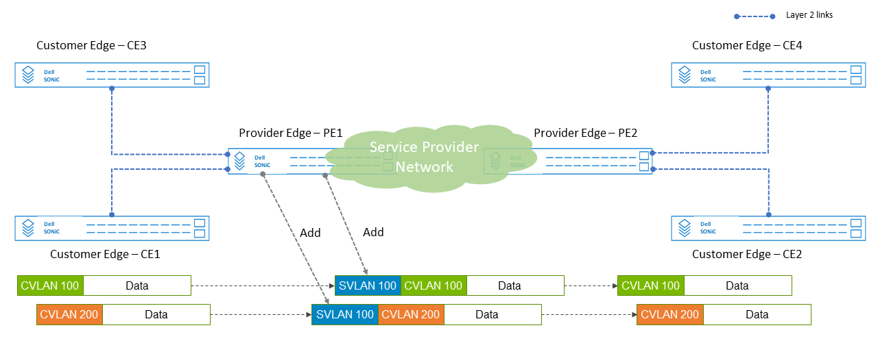
The connections from the customer edge to the provider edge switches are a Layer 2 tagged link.
The following figure shows two tenants, A, and B. Each tenant has been assigned a unique VLAN (100 = A, 200 = B). A common service provider VLAN 300 has been configured to transport both tenant's data.
In this scenario, two use cases are shown. Use case 1 has identical services such as VoIP (Voice over IP) from each tenant but remain separate. Use case 2 has two different services from each tenant (A = VoIP, B = Video) and leverage a single service provider VLAN.
Figure 8. Dell Enterprise SONiC Q-in-Q Tunneling
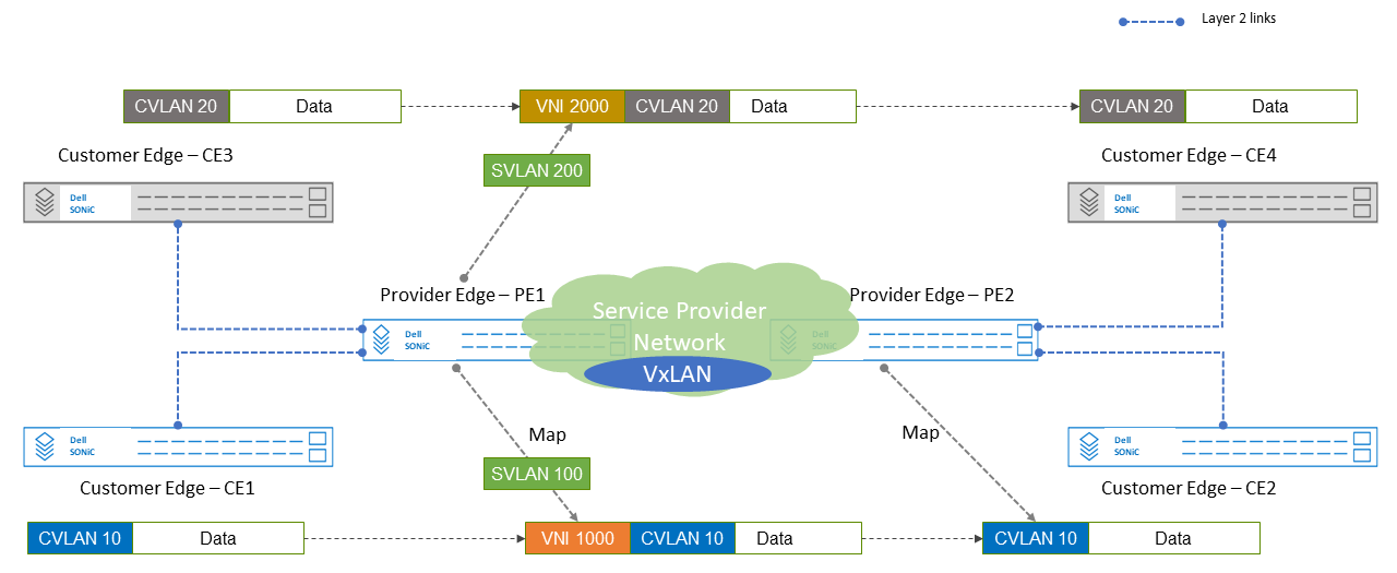
The following figure shows Q-in-Q tunneling with VxLAN. In this scenario, the customer VLAN (CVLAN) is mapped to a service provider VLAN (SVLAN). The SVLAN maps to a VNI which is used inside the service provider's VxLAN infrastructure and switched across. At egress, only the customer VLAN is retained and used to reach its destination.
Figure 9. Dell Enterprise SONiC Q-in-Q tunneling - with VxLAN
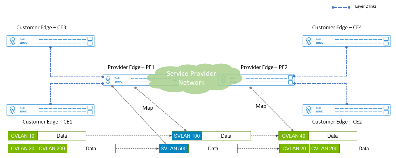
The following figure shows VLAN translation without VxLAN overlay. In this scenario, a single or double tagged customer VLAN (CVLAN) is mapped or translated with a service provider VLAN (SVLAN).
The customer traffic is switched within the service provider infrastructure using the service provider VLAN (SVLAN). Upon egress, the customer VLAN is reapplied and forwarded to the proper customer edge switch.
Figure 10. Dell Enterprise SONiC VLAN translation - No VxLAN
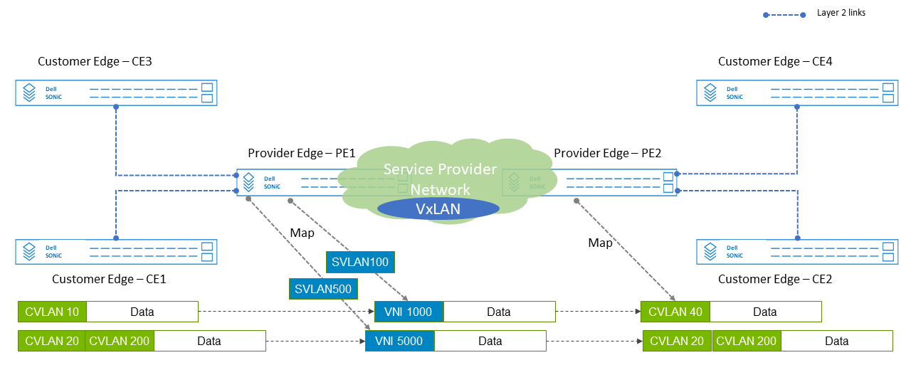
The following figure shows VLAN translation with VxLAN. In this scenario, the customer vlan (CVLAN 10) is replaced with the service provider VLAN (SVLAN 100) which is then mapped to a VxLAN VNI (VNI 200) and then forwarded within the service provider infrastructure VxLAN overlay using this VNI.
At the egress of the provider network, the VNI is then mapped back to a customer VLAN by the PE device and forwarded to the respective customer edge switch.
Figure 11. Dell Enterprise VLAN Translation with VxLAN
Deployment best practices
The following guidelines should be followed when deploying Q-in-Q and VLAN translation:
Q-in-Q guidelines
Configuration of the same S-VLAN for Q-in-Q and VLAN translation is not supported on an interface or port channel.
Only Layer 2 traffic is supported on an S-VLAN; Layer 3 configuration is not supported.
Spanning-Tree and IGMP snooping are not supported on an S-VLAN used for Q-in-Q tunneling.
Only Tag Protocol Identifier (TPID) 0x8100 is supported.
VLAN stacking must be enabled on the Z9432F and S5448F before enabling Q-in-Q. Other platforms do not require these steps.
Customer edge switch ports connecting to the provider edge switch must be configured as trunk ports.
VLAN Translation guidelines
Configuration of the same S-VLAN for both Q-in-Q and VLAN translation is not supported on an interface or port channel.
Configuration of an S-VLAN for more than one VLAN translation is not supported.
Only Layer 2 traffic is supported on an S-VLAN; Layer 3 configuration is not supported.
VLAN stacking must be enabled on the Z9432F and S5448F before enabling VLAN translation.
Customer edge switch ports connecting to the provider edge switch must be configured as trunk ports.