Home > Integrated Products > VxRail > Guides > Architecture Guide—VMware Cloud Foundation 5.1 on VxRail > Transport node profiles
Transport node profiles
-
A transport node is either a host or an Edge VM. The host transport uses a vDS for connectivity, whereas the Edge transport node uses the N-VDS. Each transport node can be added to one or more transport zones. Transport node profiles are used for host transport nodes. They contain the following information about the transport node that is vDS backed:
- Name
- Transport zones for vDS participation – Overlay and VLAN TZ
- Uplink profile
- IP assignment type for the TEPs – DHCP or IP pool
- Physical NIC mapping – VMNICs to uplinks
The underlying vDS determines which pNICs are mapped in the transport node profile. If a system vDS is used for NSX, the pNIC can be mapped to the same pNICs used for external management, vMotion, or vSAN. If a dedicated vDS is used for NSX, the pNICs are selectable, and either two or four uplinks can be mapped.
The following table shows the settings that are applied to the Mgmt WLD and VI WLD with a VxRail vDS or the second NSX, or if a dedicated NSX vDS is used with only two uplinks:
Table 12. NSX transport node profiles with two uplinks
WLD type
Transport zones
Uplink profile
IP assignment
Physical NIC mapping
Mgmt WLD
Host Overlay, VLAN
Mgmt WLD Host Uplink Profile
DHCP, IP Pool
pNIC1, pNIC2
VI WLD01
Host Overlay
VI WLD Host Uplink Profile 01
DHCP, IP Pool
pNIC1, pNIC2
During the deployment of the Mgmt WLD by Cloud Builder, the following tasks are performed:
- A transport profile is created with the settings in the preceding table. When the management VxRail cluster is added to the NSX Mgmt WLD, the transport node profile is applied to the nodes in the VxRail cluster.
- The nodes are added to the transport zones.
- The TEPs are assigned an IP so that the hosts can communicate over the overlay network.
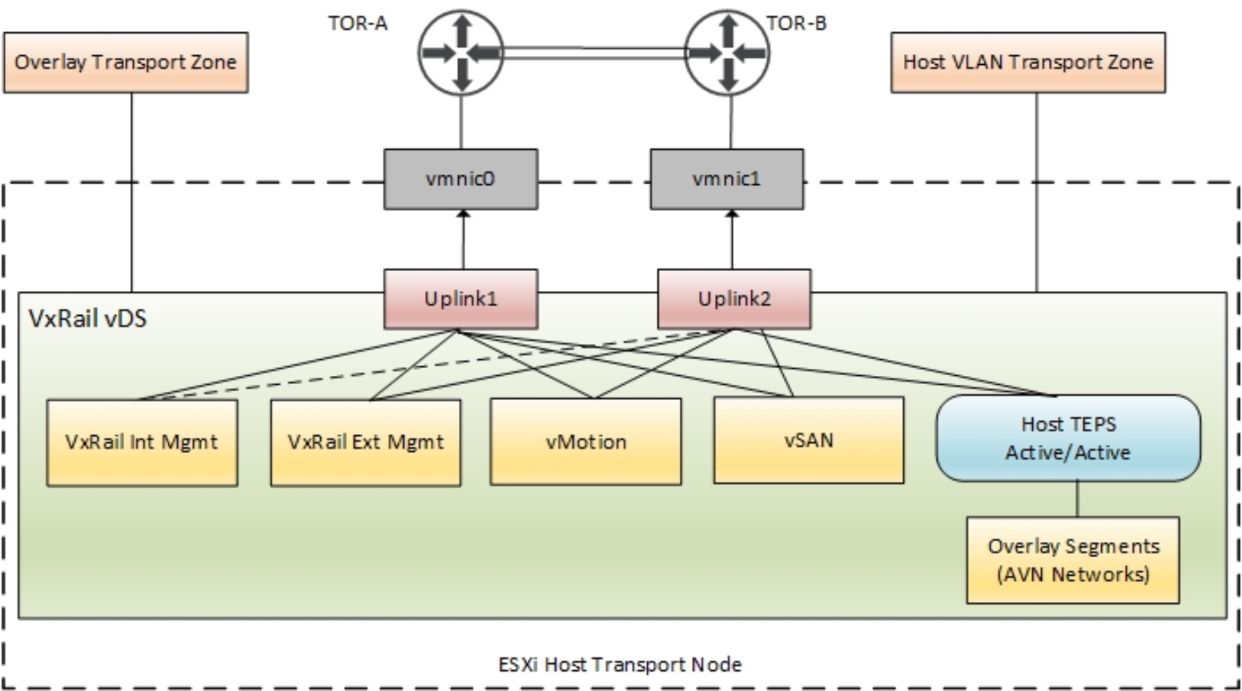
The following figure shows the Mgmt WLD node connectivity with single VxRail vDS with two uplinks that are used for the TEP traffic. The VMkernel interfaces that are used for the TEP traffic get their IPs assigned from a DHCP server or from an IP Pool. They communicate over the Host overlay VLAN defined before the deployment.

Figure 28. Mgmt WLD transport node – single VxRail vDS (only two uplinks)
Note: The preceding figure shows the AVNs that are deployed when AVN is deployed from the SDDC Manager (Day-2).
The NSX VI WLD transport zone design is similar to the Mgmt WLD. The two main differences are:
- No VLAN Transport Zone is added to the Transport Node profile during deployment.
- More VLAN transport zones can be added for the VI WLD nodes post deployment.
If NSX is deployed using a dedicated vDS, either two or four uplinks can be used, and the pNICs are selectable. The following table shows the transport node profile configuration with four uplinks:
Table 13. NSX transport node profiles with four uplinks
WLD type
Transport zones
Uplink profile
IP assignment
Physical NIC mapping
Mgmt WLD
Host Overlay, VLAN
Mgmt WLD Host Uplink Profile
DHCP, IP Pool
User Selectable:
pNIC1, pNIC2, pNIC3, pNIC4
VI WLD01
Host Overlay
VI WLD Host Uplink Profile 01
DHCP, IP Pool
User Selectable:
pNIC1, pNIC2, pNIC3, pNIC4
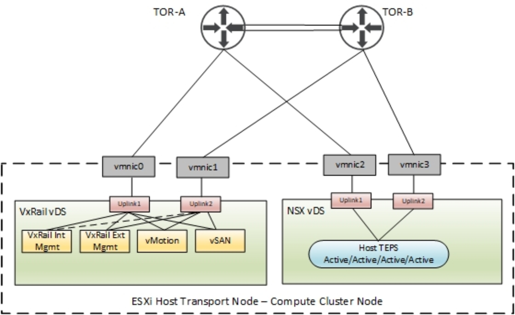
The following figure shows a VI WLD node connectivity with a dedicated NSX vDS with two uplinks that are used for the TEP traffic. The VMkernel interfaces that are used for the TEP traffic get their IPs assigned from a DHCP server or from an IP Pool. They communicate over the Host overlay VLAN provided during the deployment.

Figure 29. VI WLD transport node – Second NSX vDS (can be two or four uplinks).
