Home > Integrated Products > VxRail > Guides > Architecture Guide—VMware Cloud Foundation 5.1 on VxRail > Multi-AZ connectivity requirements
Multi-AZ connectivity requirements
-
The following table shows the supported connectivity for the data nodes sites for the different traffic types between sites.
Table 16. Site connectivity and MTU
Traffic type
Connectivity options
Minimum MTU
Maximum MTU
Default configuration
External Management
L2 Stretched
1500
9000
1500
vSAN
L3 Routed
1500
9000
1500
vMotion
L3 Routed/ L2 Stretched
1500
9000
1500
Host TEP
L3 Routed
1600
9000
9000
Witness vSAN
L3 Routed to Witness Site
1500
9000
1500
Mgmt WLD- Edge TEP (AVN Enabled)
L2 Stretched
1600
9000
9000
Mgmt WLD - Edge Uplink 01 (AVN Enabled)
L2 Stretched
1500
9000
9000
Mgmt WLD - Edge Uplink 02 (AVN Enabled)
L2 Stretched
1500
9000
9000
VI WLD -Edge TEP
L2 Stretched
1500
9000
User Input
VI WLD - Edge Uplink 01
L2 Stretched
1500
9000
User Input
VI WLD - Edge Uplink 02
L2 Stretched
1500
9000
User Input
Increasing the vSAN traffic MTU to improve performance requires the MTU for the Witness traffic to the Witness site to also use an MTU of 9000. This requirement might cause an issue if the routed traffic needs to pass through firewalls or use VPNs for site-to-site connectivity. Witness traffic separation is one option to work around this issue but is not yet officially supported for VCF on VxRail.
Note: Witness Traffic Separation (WTS) is not officially supported. If the use of WTS is a requirement, the configuration can be supported through the RPQ process. The VxRail vSAN stretched cluster with Witness Traffic Separation requires a manual procedure to configure WTS interfaces and create static routes. It also has an impact on the Day 2 node expansion procedure.
The vSAN traffic can only be extended using Layer 3 routed networks between sites. The vMotion traffic can be stretched Layer 2 or extended using Layer 3 routed networks, Layer 3 is recommended. The external management traffic must be stretched Layer 2 only to ensure that the management VMs do not need re-IP when they are restarted on AZ2 if AZ1 fails. The Geneve overlay network can either use the same or different VLANs for each AZ. The same VLAN can be used at each site nonstretched, or a different VLAN can be used at each site allowing the traffic to route between sites. The following table shows the management WLD sample VLAN and sample IP subnets:
Table 17. Mgmt WLD sample VLAN and IP subnets
Traffic type
AZ1
AZ2
Sample VLAN
Sample IP range
External Management
ü
ü
1611 (stretched)
172.16.11.0/24
VxRail Discovery
ü
ü
3939
N/A
vSAN
ü
û
1612
172.16.12.0/24
vMotion
ü
û
1613
172.16.13.0/24
Host TEP
ü
û
1614
172.16.14.0/24
Edge TEP
ü
ü
2711 (stretched)
172.27.11.0/24
Edge Uplink 01
ü
ü
2712 (stretched)
172.27.12.0/24
Edge Uplink 02
ü
ü
2713 (stretched)
172.27.13.0/24
vSAN
û
ü
1621
172.16.21.0/24
vMotion
û
ü
1622
172.16.22.0/24
Host TEP
û
ü
1623
172.16.23.0/24
The VVS requirements for the VI WLD are the same as for the Mgmt WLD. If Edge Nodes are deployed, the Edge TEP and uplink networks must be stretched Layer 2 between sites. However, if stretched Layer 2 does not meet the requirements, implementing a different design might be possible. For alternative designs, consult VMware during the design phase of the project.
Table 18. VI WLD sample VLAN and IP subnets
Traffic type
AZ1
AZ2
Sample VLAN
Sample IP range
External Management
ü
ü
1631 (stretched)
172.16.31.0/24
VxRail Discovery
ü
ü
3939
N/A
vSAN
ü
û
1632
172.16.32.0/24
vMotion
ü
û
1633
172.16.33.0/24
Host TEP
ü
û
1634
172.16.34.0/24
Edge TEP
ü
ü
2731 (stretched)
172.27.31.0/24
Edge Uplink 01
ü
ü
2732 (stretched)
172.27.32.0/24
Edge Uplink 02
ü
ü
2733 (stretched)
172.27.33.0/24
vSAN
û
ü
1641
172.16.41.0/24
vMotion
û
ü
1642
172.16.42.0/24
Host TEP
û
ü
1643
172.16.43.0/24
The following figure illustrates the VLAN requirements for the Mgmt, and first WLD for a VCF multi-AZ VxRail vSAN stretched cluster deployment:
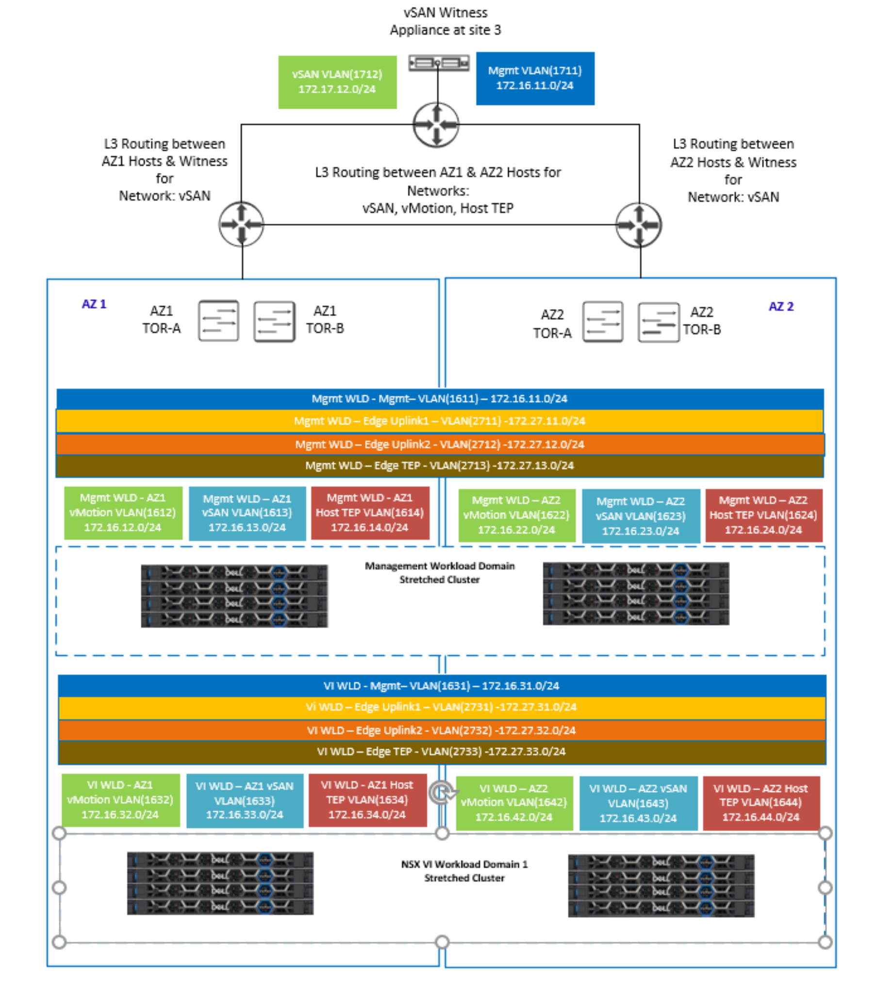
Figure 50. VLAN and network requirements for multi-AZ (VxRail vSAN stretched cluster)
Multi-AZ component placement
During the VxRail vSAN stretched cluster configuration, the management VMs are configured to run on the first AZ by default. Host/VM groups and affinity rules keep these VMs running on the hosts in AZ1 during normal operation. The following figure shows where the management and NSX VMs are placed after the stretched configuration is complete for the Mgmt WLD and the first VxRail cluster of an NSX VI WLD:
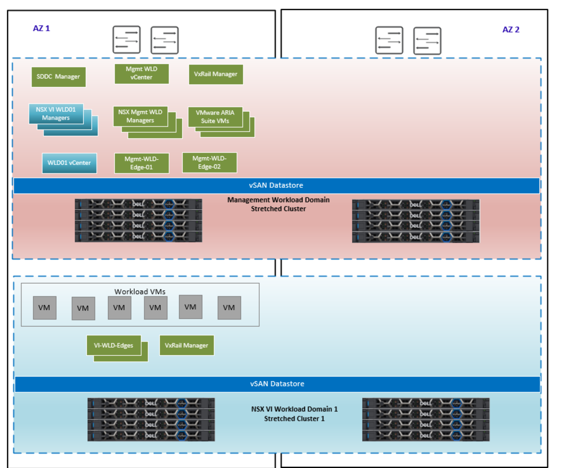
Figure 51. Multi-AZ component layout
Multi-AZ supported topologies
In this next section, we cover some of the different deployment options for a multi-AZ deployment. The management WLD VxRail cluster must always be stretched but the VI WLD VxRail clusters can either be local, stretched, or remote. The VI WLDs can use a shared NSX instance (1:many), or they can use a dedicated NSX instance for each VI WLD (1:1). This first figure shows a standard multi-AZ VxRail vSAN stretched cluster deployment with a stretched Mgmt WLD and one stretched VI WLD with one VxRail cluster and a single NSX instance.
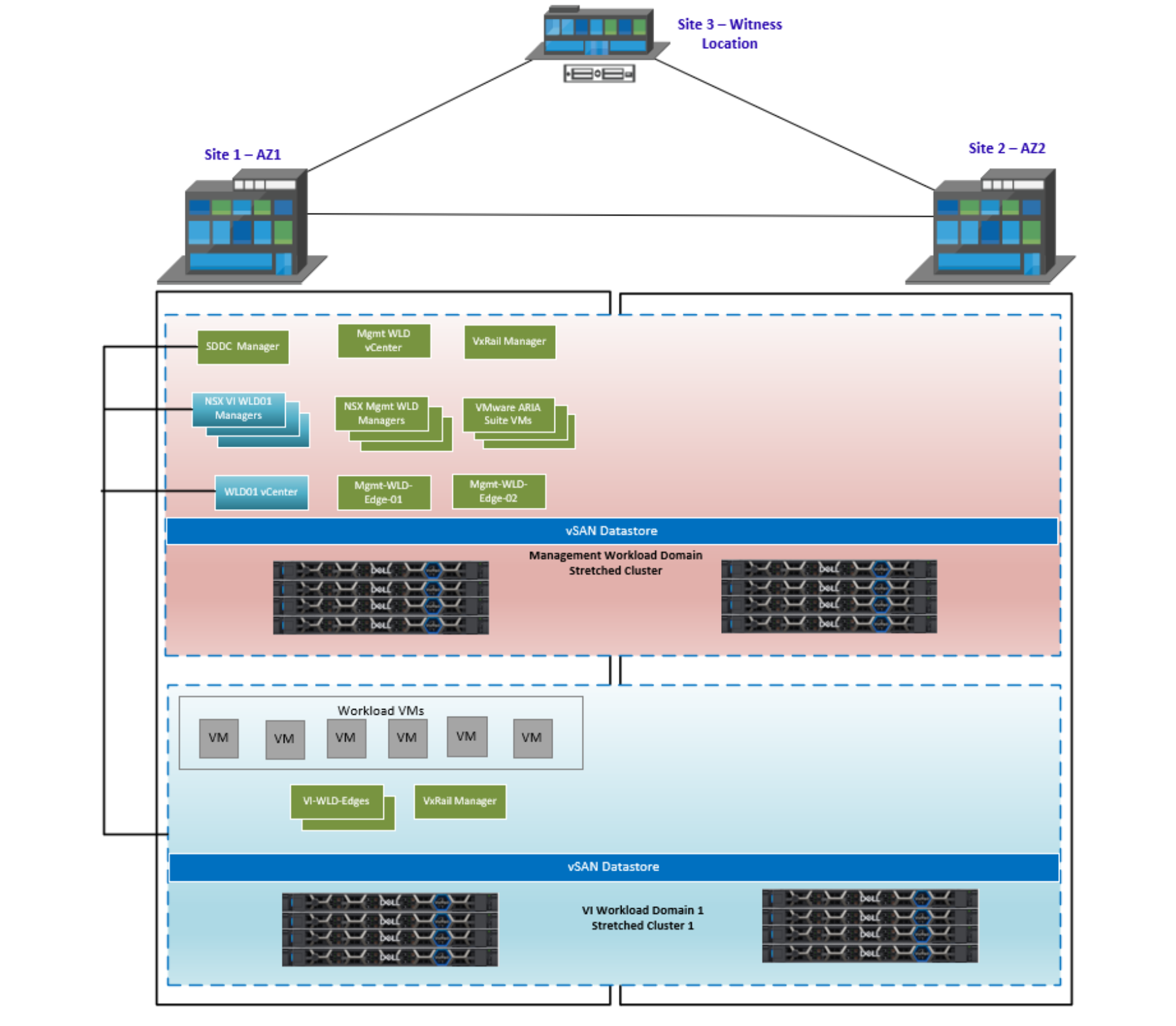
Figure 52. Mgmt and single VI WLD stretched
In the next figure, we have a stretched management WLD and two VI WLDs stretched but using a single NSX instance for the two VI WLDs. A single NSX Edge cluster is used for both VI WLD VxRail clusters.
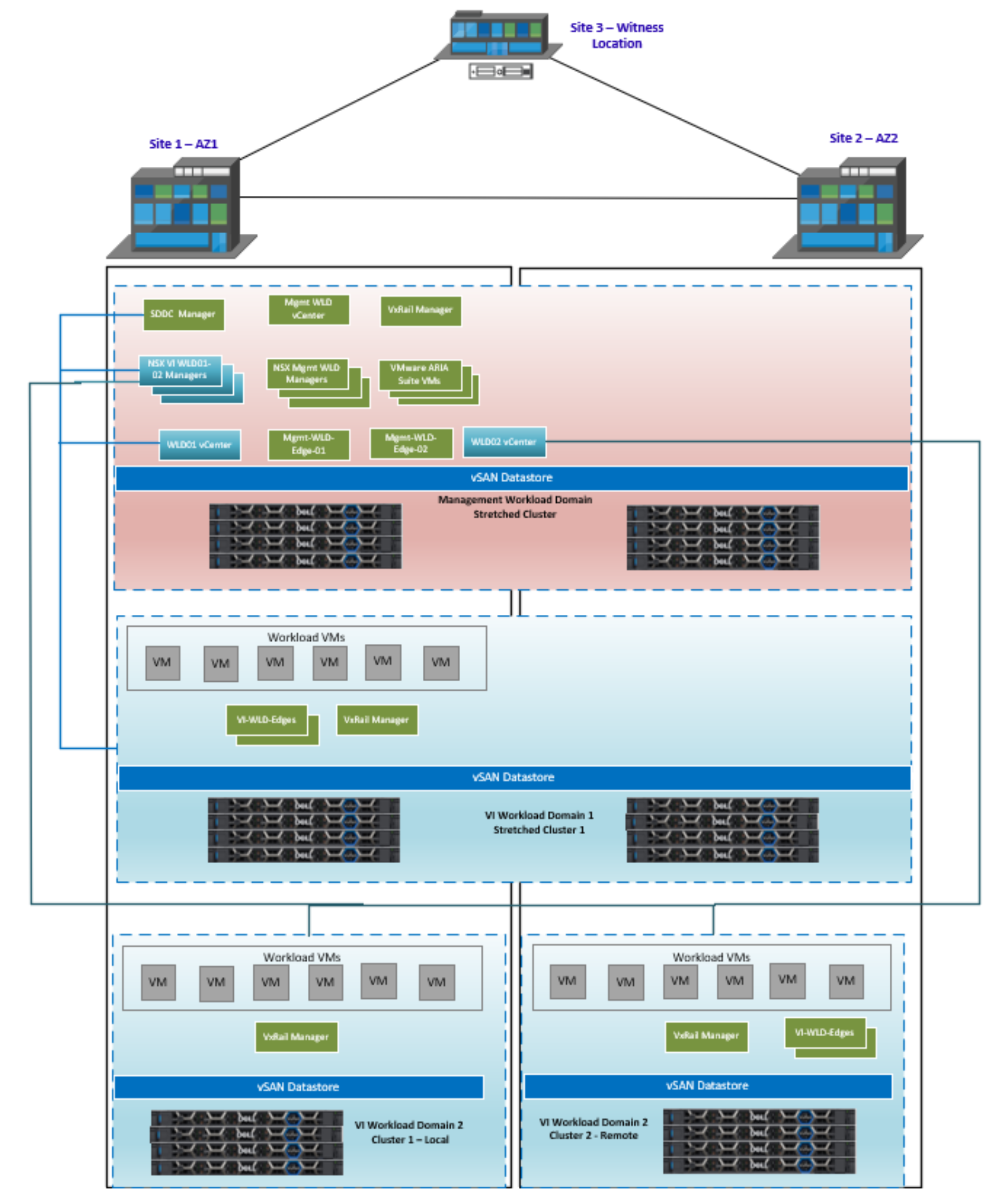
Figure 53. Mgmt and two VI WLD stretched
The next figure illustrates the concept of mixing local and stretched clusters in dual AZ. In this scenario, we have a stretched management WLD and two VI WLDs with a single NSX instance. The first VI WLD has one stretched VxRail cluster, and the second VI WLD has two clusters—one cluster at site 1 and the second at site 2. A dedicated NSX Edge cluster is deployed on the cluster at site 2.
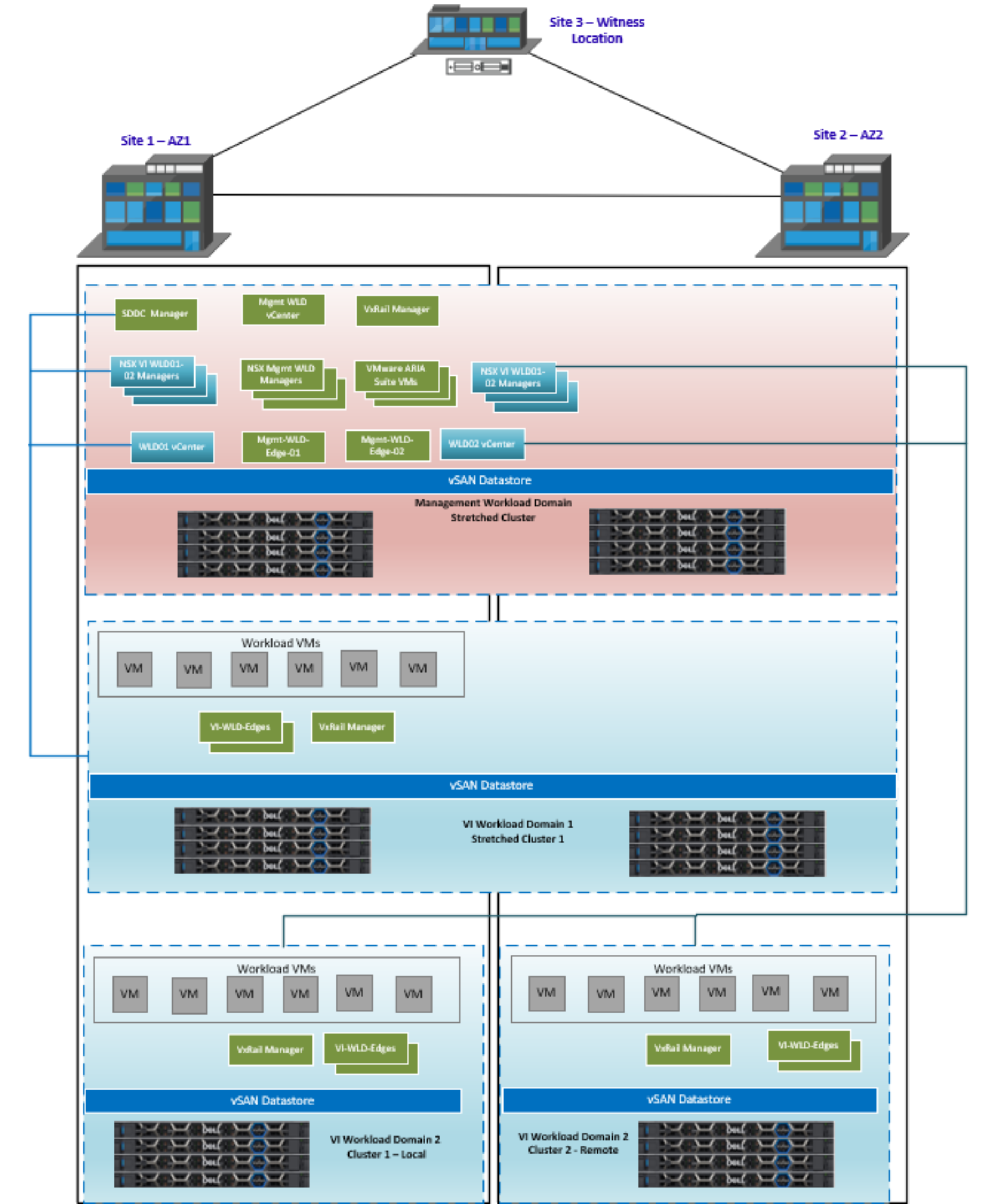
Figure 54. Mgmt and VI WLD01 stretched, nonstretched in VI WLD02
The final topology, illustrated in the next figure, is similar to the previous design. This time, we have a second NSX instance that is deployed to manage the network virtualization for WLD02. This design is considered a 1:1 NSX design, where each WLD has a dedicated NSX instance. We also have dedicated Edges for both VxRail clusters at each site in WLD02, which prevents traffic hair pinning between sites and keeps traffic local to the site.
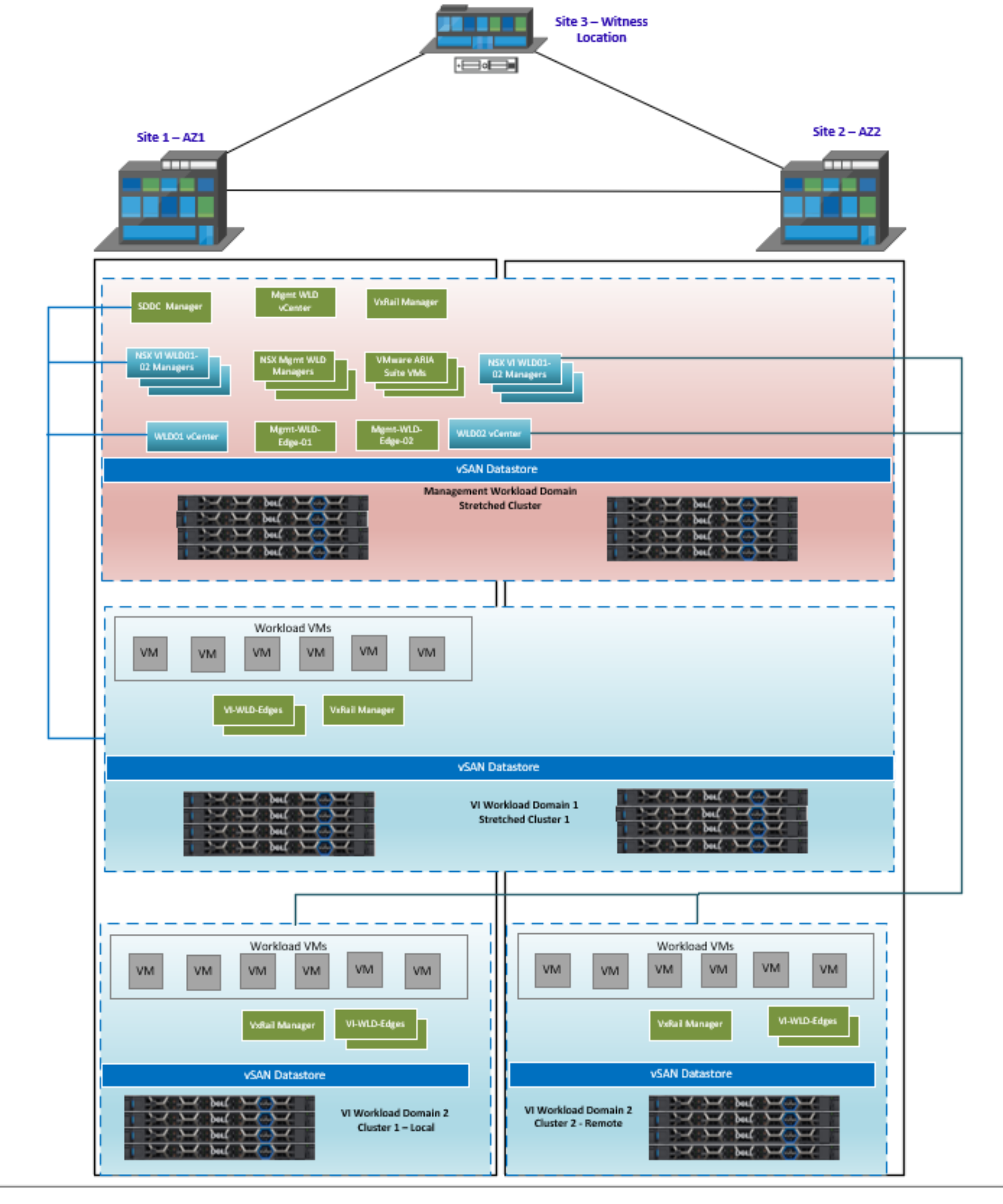
Figure 55. Mgmt and VI WLD01 stretched, nonstretched VI WLD02 with 1:1 NSX
Management WLD multi-AZ – VxRail vSAN stretched-cluster routing design
As previously mentioned, with AVN overlay networks deployed, the Edge Nodes are deployed and configured to enable the management components in the Aria Suite to use this network. With multi-AZ, the north-south routing that occurs through AZ1 would need to fail over to AZ2 if there is a full site failure. This failover ability is achieved through the addition of the AZ2 TOR switches as BGP neighbors to the Tier 0 gateway so that traffic from the Tier 1 can flow through the TORs at either site. Using both BGP local preference and Path prepend configured on the Tier 0 gateway to steer the traffic out of AZ1 in normal operating conditions requires manual Day 2 configuration. This configuration is outlined in NSX Data Center Configuration for Availability Zone 2.
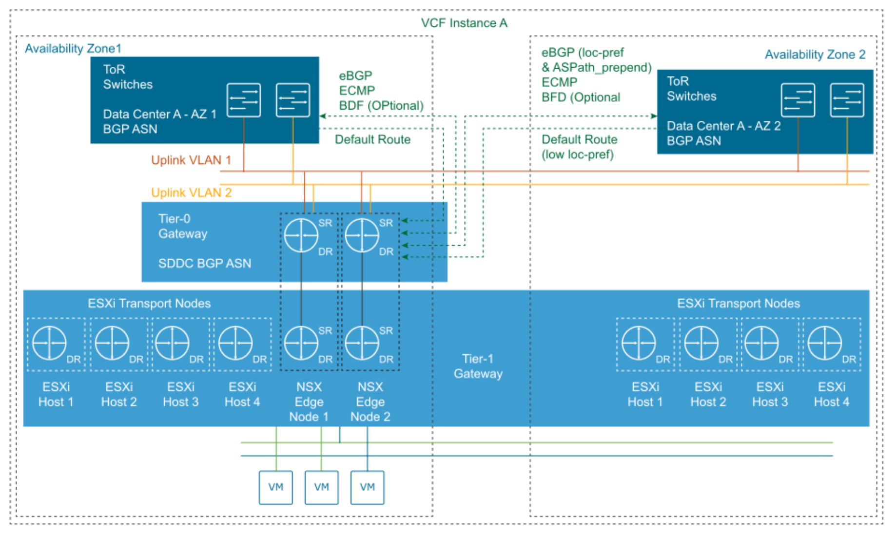
Figure 56. Multi AZ – Mgmt WLD VCF routing design
