Home > Integrated Products > VxRail > Guides > Architecture Guide—VMware Cloud Foundation 5.1 on VxRail > Leaf and spine Layer 3 fabric
Leaf and spine Layer 3 fabric
-
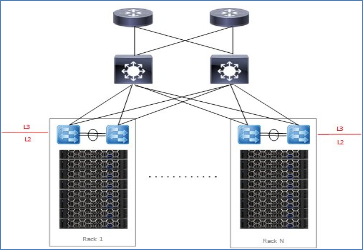
The Layer 3 leaf and spine design is becoming the more adopted design for newer, more modern data center fabrics depicted in the following figure:

Figure 36. Leaf and spine Layer 3 design
It has the following characteristics:
- L3 is terminated at the leaf, thus all the VLANs originating from ESXi hosts terminate on leaf.
- The same VLANs can be reused for each rack.
- The leaf switches provide default gateway functionality.
- The NSX T0 Gateway for the WLD peers with the leaf switches in one rack.
Advantages:
- Vendor agnostic - Multiple network hardware vendors can be used in the design.
- Reduced VLAN span across racks, thus smaller broadcast domains.
- East-west for an NSX domain can be confined within a rack with intra-rack routing at the leaf.
- East-west across NSX domains or cross-rack is routed through the spine.
- NSX Tier 0 peering is simplified by peering the WLDs with the leaf switches in the rack.
Disadvantages:
- The Layer 2 VLANs cannot span racks. VxRail clusters that span racks require a solution to allow VxRail system traffic to span racks using hardware VTEPs.
- The Layer 3 configuration might be more complex to implement.
