Home > Integrated Products > VxRail > Guides > Architecture Guide—VMware Cloud Foundation 3.10.01 on VxRail > NSX-V based WLD
NSX-V based WLD
-
As documented in previous sections, there are two types of WLD domains pertaining to NSX: NSX-V based and NSX-T. The Mgmt WLD is only NSX-V based, but VI WLD domains can be either NSX-V or NSX-T.
NSX-V physical network requirements
NSX-V has the following external network requirements that must be met before the VCF on VxRail solution can be deployed.
- MTU 9000 for VXLAN traffic (for multi-site dual AZ ensure MTU across ISL)
- IGMP Snooping for VXLAN VLAN on the first hop switches
- IGMP querier is enabled on the connected router or Layer 3 switch.
- VLAN for VXLAN is created on the physical switches.
- DHCP is configured for VXLAN VLAN to assign the VTEPs IP.
- IP Helper on the switches if the DHCP server is in different L3 network
- Layer 3 license requirement for peering with ESGs
- BGP is configured for each router peering with an ESG.
- Two Uplink VLANs for ESGs in Mgmt WLD
- AVN subnets are routable to the Mgmt WLD management network.
- AVN networks are routable at the Core network to reach external services.
NSX-V deployment in management WLD
The deployment of the Mgmt WLD includes installation of NSX components and layers down the Application Virtual Network (AVN) for the vRealize Suite. It deploys the Edge services gateway (ESG) VMs and the universal logical router (uDLR) and configures dynamic routing to allow traffic from the AVNs to the external networks. The following steps are performed by the VCF Cloud Builder to deploy and configure NSX during the Mgmt WLD bring-up process:
- Create two ESG uplink port groups on the vDS.
- Deploy NSX Manager in Mgmt WLD cluster.
- Register NSX Manager with PSC01.
- Register NSX Manager with Mgmt WLD VC.
- Install license for NSX.
- Set NSX Manager as the Primary NSX manager.
- Deploy three NSX controllers to Mgmt WLD cluster.
- Create anti-affinity rules for controllers.
- Create VXLAN segment ID range.
- Create a VXLAN Multicast IP range.
- Create a universal transport zone.
- Add cluster to transport zone.
- Install NSX VIBs (host prep).
- Create VXLAN port group.
- Create Host VTEPs.
- Deploy 2x ESGs.
- Create anti-affinity rules for the ESCGs.
- Deploy uDLR.
- Create anti-affinity rules for the uDLR Control VMs.
- Configure Dynamic Routing.
- Create AVN Networks for vRealize Suite.
Figure 15 shows the NSX-V components that are deployed after the VCF bring-up process is completed.
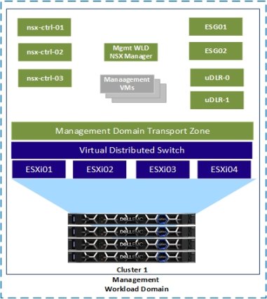
Figure 15. Management WLD after initial deployment
NSX-V deployment in the VI WLD
Although the deployment of NSX-V in the WLD is becoming less common as NSX-T becomes the standard network virtualization platform, we still want to cover the deployment of an NSX-V VI WLD. SDDC Manager is used to deploy the NSX-V WLD. The fundamental difference is that NSX-V Edge routing is not deployed or configured, and no Universal objects are created during the deployment. The following steps are performed by SDDC Manager to deploy and configure NSX-V during the VI WLD deployment process.
- Deploy VI WLD NSX Manager in Mgmt WLD cluster.
- Register NSX Manager with PSC01.
- Register NSX Manager with VI WLD VC.
- Install license for NSX.
- Deploy three NSX controllers to VI WLD cluster.
- Create anti-affinity rules for controllers.
- Create VXLAN segment ID range.
- Create a VXLAN Multicast IP range.
- Create a global transport zone.
- Add cluster to transport zone.
- Install NSX VIBs (host prep).
- Create VXLAN port groups.
- Create Host VTEPs.
Figure 16 shows the NSX-V components that are deployed after an NSX-V WLD domain has been added and a second cluster has been added to the VI WLD. Note when a second cluster is added, only the preceding Steps 10, 11 and 13 are performed by SDDC Manager.
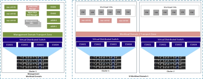
Figure 16. Management WLD and NSX-V VI WLD with two clusters
NSX-V transport zone design
A transport zone controls which hosts a logical switch can reach and span one or more vSphere clusters. Transport zones dictate which clusters and, therefore, which VMs can participate in the use of a Layer 2 network.
Management WLD transport zone
The Mgmt WLD has a dedicated NSX-V Manager. It has its own transport zone created during the VCF bring-up process, the transport zone is created as a universal transport zone, universal objects can span sites. This is important for multi-region deployments that will be supported in a later release of the solution. Figure 17 shows the Mgmt WLD transport zone as a universal transport zone. Associated with this transport zone is the universal multicast IP range that will be used for the Universal Logical Switches or AVNs.
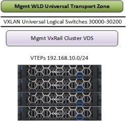
Figure 17. Management WLD Universal Transport Zone
VI WLD transport zone
When creating a VI WLD, the SDDC Manager creates the transport zone while the first cluster is added to the VI WLD. Subsequent clusters are added to the transport zone. This allows VMs in a WLD on the same logical switch to span clusters. This can be useful when designing three-tier applications using a flat Layer 2 but keeping different workloads on different clusters. Micro-segmentation provides security between the different tiers of the application. Figure 18 shows the transport zone configuration for a VI WLD with three clusters added. As each cluster is added, it is added to the transport zone.
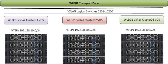
Figure 18. NSX-V based VI WLD Transport Zone
NSX-V logical switch control plane replication mode
The control plane decouples connectivity in the logical space from the physical network infrastructure and handles the broadcast, unknown unicast, and multicast (BUM) traffic within the logical switches. The control plane is on top of the transport zone and is inherited by all logical switches that are created within it. VCF on VxRail uses the hybrid replication mode to send BUM traffic. This mode is an optimized version of the unicast mode where local traffic replication for the subnet is offloaded to the physical network. Hybrid mode requires IGMP snooping on the first-hop switch and access to an IGMP querier in each VTEP subnet or VLAN. Using VLANs for the management domain VXLAN VLAN that are different than the VLANs used for WLDs is recommended to completely isolate the management and tenant traffic in the environment. The hybrid replication mode operation is depicted in Figure 19, where a specific VTEP performs replication to the other local VTEPs. This VTEP uses L2 multicast to replicate BUM frames locally, while the unicast is used to send the traffic to a designate VTEP in a remote L3 segment. This performs the same L2 multicast replication in that segment.
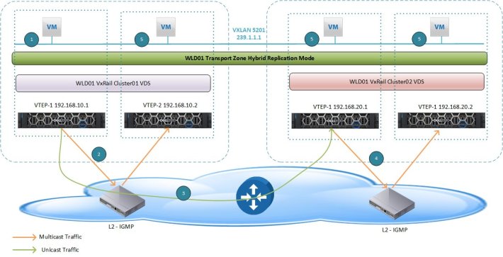
Figure 19. Hybrid Replication Mode across Clusters in VI WLD
Management WLD Application Virtual Network
The Application Virtual Network (AVN) is a term used to describe the network used to connect certain management applications running in the management workload to NSX-V backed logical switches. Starting with version 3.9.1, virtual routing is deployed for the management WLD using cloud builder to allow the deployment of the vRealize Suite onto the AVN or NSX-V Universal logical switches. This is to prepare for a future release where a Multi-Region disaster recovery solution can be adopted to allow the failover and recovery of the vRealize suite in the case of a full site failure.
Notes:
- Any VCF environments upgraded from 3.9 will not automatically get AVN deployed, the Log Insight VMs remain on the Management network and the vRealize suite would remain on a VLAN backed network, if migration to AVN is required it will need to be done manually. See VCF 3.9.1 release notes for further details VCF 3.9.1 Release Notes.
- For VCF version 3.9.1 AVN deployment was mandatory, for VCF version 3.10 the AVN deployment is optional, if AVN is not enabled during deployment the Log Insight VMs remain on the Management network and the vRealize suite would remain on a VLAN backed network, if migration to AVN is required it will need to be done manually with support from VMware.
The topology that is required for AVN is shown in Figure 20.
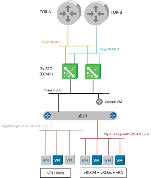
Figure 20. AVN connectivity for Management WLD
AVN contains the following components:
- Dual TOR switches running BGP protocol
- Two Edge VLANs are used as transit for the ESG uplinks to each upstream router.
- Two ESGs in ECMP mode
- One Universal Transit Logical Switch connecting ESGs to uDLR
- One uDLR
- Two Universal Logical Switches for the AVN
During the deployment, anti-affinity rules are used to ensure the NSX Controllers, uDLR Control VMs and the ESGs do not run on the same node simultaneously. This is critical to prevent impact to the network services if one host fails in the management WLD. The following diagram illustrates how these components are typically separated by the anti-affinity rules that are created and applied during the management WLD deployment.

Figure 21. Mgmt WLD NSX Component Layout
To expand on the routing design, Figure 22 shows a typical BGP configuration for the management workload domain deployment. This figure shows the eBGP peering between the Mgmt WLD ESGs and the upstream switches and iBGP is used between the ESGs and the uDLR.
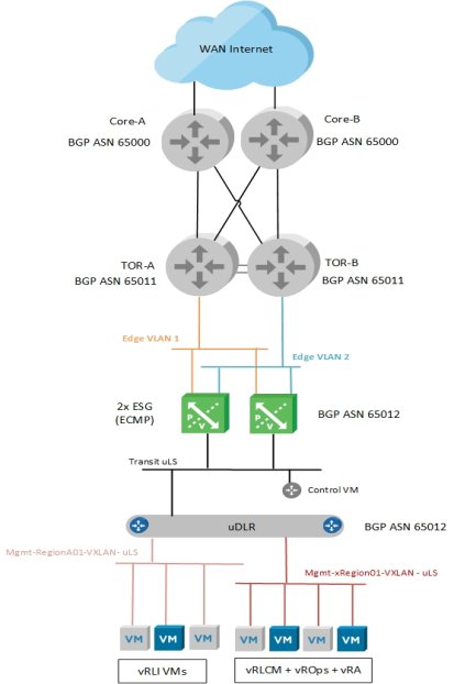
Figure 22. AVN NSX Virtual Routing for Management WLD
The following network BGP configuration is implemented as part of the deployment:
- eBGP neighbors that are created between both ESGs and both TORs
- BGP Password is applied in the neighbor configuration.
- BGP timers of 4/12 applied to the eBGP TOR neighbor
- Static routes created on the ESGs to protect against uDLR control VM failing.
- Redistribute connected and static routes from ESG to uDLR.
- iBGP configured between ESGs and uDLR
- BGP timers of 1/3 applied to iBGP uDLR neighbor
- Redistribute connected and static routes from uDLR to ESG.
As mentioned previously, the AVN networks must be routable to the VLAN backed management network for the management WLD and also any management networks for any additional VI WLDs that are deployed. This allows the management components on the AVN network to communicate to the VLAN backed management components on the VI WLD. For example, Log Insight VMs on the AVN network must communicate with hosts on a VI WLD management network. Figure 23 illustrates the connectivity and VLANs required for communication between management WLD components on the management VLAN backed network and the vRealize components on the AVN network. Any VI WLDs that are added would have similar connectivity requirements. In this example, the two AVN subnets 172.16.11.0/24 and 172.16.12.0/24 must be routable to the management network VLAN 100 and subnet 192.168.100.0/24.
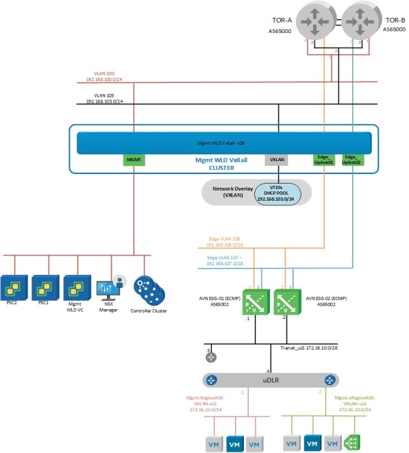
Figure 23. AVN connectivity to Mgmt WLD management network
