Home > Storage > PowerFlex > White Papers > Amazon Elastic Kubernetes Service Anywhere Bare Metal on Dell PowerFlex > Solution architecture
Solution architecture
-
This section describes how Amazon EKS Anywhere Bare Metal is deployed on a Dell PowerFlex bare metal server. This solution can be deployed on other Dell PowerFlex family products as well.
Note: The solution that is described here was validated in the Dell engineering lab with the hardware specification that is provided in the configuration details section.

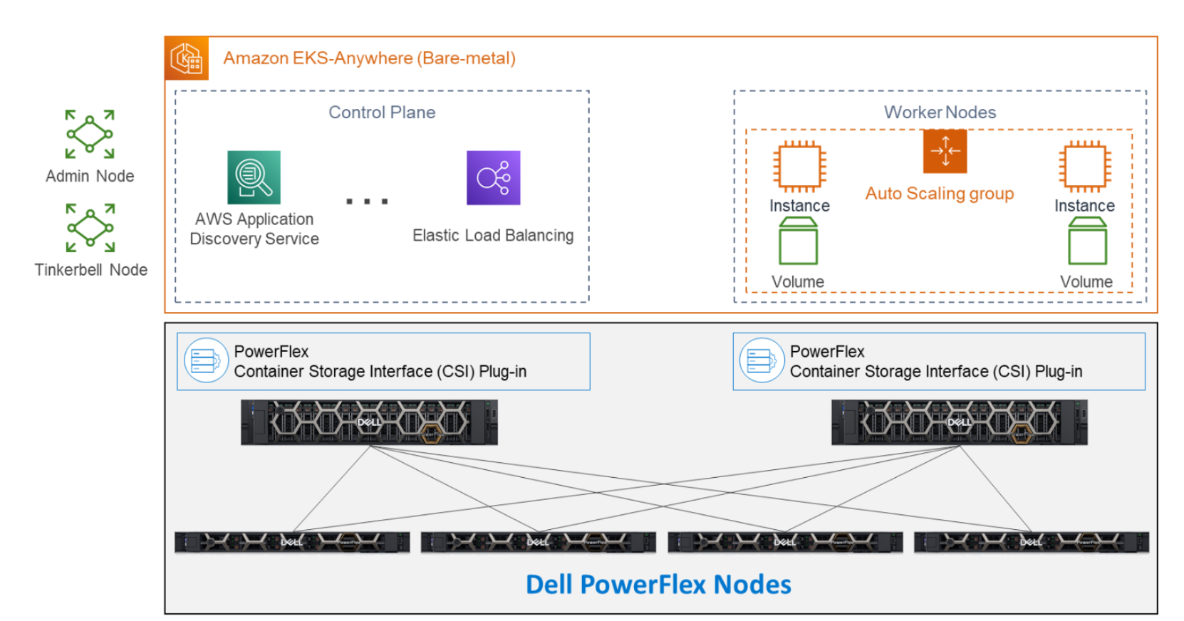
Figure 2. Bare Metal architecture of the Amazon EKS Anywhere environment on Dell PowerFlex
The bottom portion of the figure consists of PowerFlex – storage-only nodes. The center of the diagram consists of the hosts that are used for the control plane and worker nodes. These nodes are PowerFlex – compute-only nodes. On the left of the diagram are the admin and Tinkerbell nodes that are used for administration of the environment. At the upper left, we have the control plane that provides operational control and orchestration. The worker node, at the upper right, handle the workloads.
Each storage node contains five 1.4TB SAS SSD drives and two 25GbE NVIDIA Mellanox network links. For the validation, four PowerFlex storage nodes were used to provide full storage redundancy.
Amazon EKS Anywhere tinkerbell process installs the Ubuntu operating system on the two compute notes through iPXE boot process. After Ubuntu installation, SDC (Storage Data Client) and CSI (container storage interface) is installed to provide a storage provisioning interface.
This is a two-layer architecture where compute and storage nodes are separated. It is important to note that there is no hypervisor installed.
Note: The validation was performed in a nonproduction environment. For more information about the minimum hardware requirements, refer to this link: https://anywhere.eks.amazonaws.com/docs/reference/baremetal/bare-prereq/
Using a two-layer architecture makes it possible to scale resources independently as needed in the environment for optimal resource utilization. Hence, if more storage is needed, it can be scaled independently of compute. Additional compute capacity can be added to the environment as needed.
Outside the Amazon EKS Anywhere instance, there are two physical nodes. Both are central to building the control plane and worker nodes. The admin node is used to control the Amazon EKS Anywhere instance and serves as a portal to upload inventory information to the Tinkerbell node. The Tinkerbell node serves as the infrastructure services stack and is key to the provisioning and PXE booting of the bare metal servers.
The installation process requires you to create a data center hardware configuration file with the details pertaining to your physical server hardware in csv format. Target cluster creation process needs the input file to be in YAML format. The cluster config file is generated from the information provided in the hardware CSV file. With the information gathered from the cluster specification and hardware CSV file, the three custom resource definitions (CRD’s) are created. These include
- Hardware custom resources
- Template custom resources
- Workflow custom resources
The Tinkerbell process creates a local kind cluster on the admin host to install the Cluster-API (CAPI) and the Cluster-API-Provider-Tinkerbell (CAPT).
For more information about the booting and deployment process, see https://anywhere.eks.amazonaws.com/docs/reference/baremetal/netbooting-and-tinkerbell/
With the base control environment operation, CAPI creates the control plane and worker node resources, and CAPT maps and powers on the corresponding bare metal servers. The bare metal servers PXE boot from the Tinkerbell node to run corresponding roles. Kubernetes management resources are transferred from the bootstrap cluster to the target Amazon EKS Anywhere workload cluster.
The kind cluster is then deleted from the admin machine. This creates both the control plane and worker nodes. SDC drivers are installed on the worker nodes along with the Dell CSI plug-in for PowerFlex. Workloads can be deployed on the worker nodes as needed.
