
Leaf spine underlay
Leaf spine underlay
-
This section details the topology used in this configuration cheat sheet. The cheat sheet uses a Layer 3 leaf-spine topology for the network underlay.
The physical topology (underlay) provides transit for the virtual network overlays. Dell EMC Networking S5232F-ON switches are used on the spine layer with Dell EMC Networking S5248F-ON switches used on the leaf layer. In rack 1 and rack 2, both leaf switches are configured as Virtual Link Trunking (VLT) pairs. A VLT provides redundancy and load balancing between the two VLT peers, multihoming support, and a loop-free Layer 2 network without running STP. As administrators add racks to the data center, two leaf switches configured for VLT can be added to each new rack. Connections within racks from hosts to leaf switches are Layer 2, and each host is connected using a VLT port channel.
OSPF is used for communication between the leaf and spine establishes a logical, scalable IP address scheme, which is required before deploying a leaf-spine topology. Loopback addresses may be used as router IDs when configuring routing protocols. Loopback addresses should follow a logical pattern that will make it easier for administrators to manage the network and permit growth. In the following example, all loopback addresses are part of the 10.0.0.0/8 address space with each address using a 32-bit mask. The third octet represents Layer 1 for the spine and Layer 2 for leaf. The fourth octet is the counter for the appropriate layer. For example, 10.2.1.1/32 is the first spine switch in the topology while 10.2.2.2/32 is the second leaf switch.
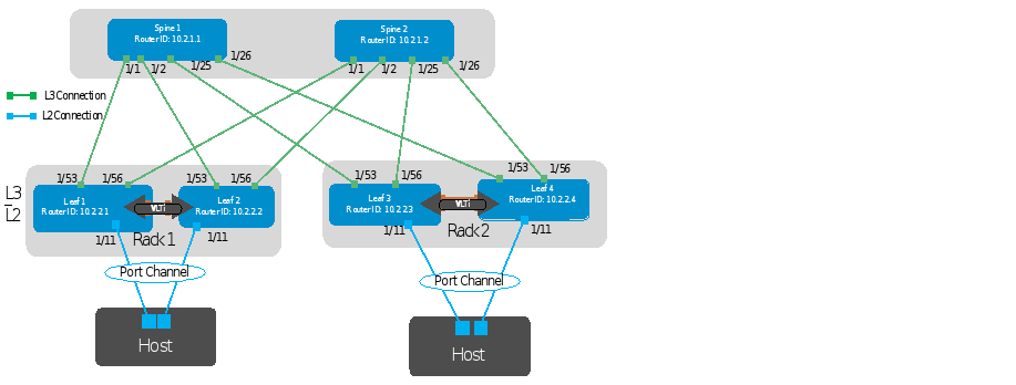
Figure 1. Leaf-Spine Underlay Topology

Figure 2. VLT topology
Establishing a logical, scalable IP address scheme is important before deploying a leaf-spine topology. The point-to-point links used in this deployment are labeled A-H in Figure 3.
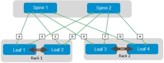
Figure 3. Point-to-point networks
Each link is a separate, point-to-point IP network. The following table details the links labeled in Figure 3. The IP addresses in the table are used in the switch configuration examples.
Link Label
Source Switch
Source IP address
Destination Switch
Destination IP address
Network
A
Spine 1
192.168.1.0
Leaf 1
192.168.1.1
192.168.1.0/31
B
Spine 2
192.168.2.0
Leaf 1
192.168.2.1
192.168.2.0/31
C
Spine 1
192.168.1.2
Leaf 2
192.168.1.3
192.168.1.2/31
D
Spine 2
192.168.2.2
Leaf 2
192.168.2.3
192.168.2.2/31
E
Spine 1
192.168.1.4
Leaf 3
192.168.1.5
192.168.1.4/31
F
Spine 2
192.168.2.4
Leaf 3
192.168.2.5
192.168.2.4/31
G
Spine 1
192.168.1.6
Leaf 4
192.168.1.7
192.168.1.6/31
H
Spine 2
192.168.2.6
Leaf 4
192.168.2.7
192.168.2.6/31
Note: As with all examples in this guide, any valid IP address scheme can be used. The example point-to-point addresses above use a 31-bit mask to save address space. This is optional and covered in RFC 3021