


Network Design for PowerScale CSI

Network connectivity is an essential part of any infrastructure architecture. When it comes to how Kubernetes connects to PowerScale, there are several options to configure the Container Storage Interface (CSI). In this post, we will cover the concepts and configuration you can implement.
The story starts with CSI plugin architecture.
CSI plugins
Like all other Dell storage CSI, PowerScale CSI follows the Kubernetes CSI standard by implementing functions in two components.
- CSI controller plugin
- CSI node plugin
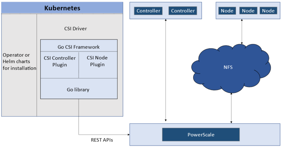
The CSI controller plugin is deployed as a Kubernetes Deployment, typically with two or three replicas for high-availability, with only one instance acting as a leader. The controller is responsible for communicating with PowerScale, using Platform API to manage volumes (to PowerScale it’s to create/delete directories, NFS exports, and quotas), to update the NFS client list when a Pod moves, and so on.
A CSI node plugin is a Kubernetes DaemonSet, running on all nodes by default. It’s responsible for mounting the NFS export from PowerScale, to map the NFS mount path to a Pod as persistent storage, so that applications and users in the Pod can access the data on PowerScale.
Roles, privileges, and access zone
Because CSI needs to access both PAPI (PowerScale Platform API) and NFS data, a single user role typically isn’t secure enough: the role for PAPI access will need more privileges than normal users.
According to the PowerScale CSI manual, CSI requires a user that has the following privileges to perform all CSI functions:
Privilege | Type |
ISI_PRIV_LOGIN_PAPI | Read Only |
ISI_PRIV_NFS | Read Write |
ISI_PRIV_QUOTA | Read Write |
ISI_PRIV_SNAPSHOT | Read Write |
ISI_PRIV_IFS_RESTORE | Read Only |
ISI_PRIV_NS_IFS_ACCESS | Read Only |
ISI_PRIV_IFS_BACKUP | Read Only |
Among these privileges, ISI_PRIV_SNAPSHOT and ISI_PRIV_QUOTA are only available in the System zone. And this complicates things a bit. To fully utilize these CSI features, such as volume snapshot, volume clone, and volume capacity management, you have to allow the CSI to be able to access the PowerScale System zone. If you enable the CSM for replication, the user needs the ISI_PRIV_SYNCIQ privilege, which is a System-zone privilege too.
By contrast, there isn’t any specific role requirement for applications/users in Kubernetes to access data: the data is shared by the normal NFS protocol. As long as they have the right ACL to access the files, they are good. For this data accessing requirement, a non-system zone is suitable and recommended.
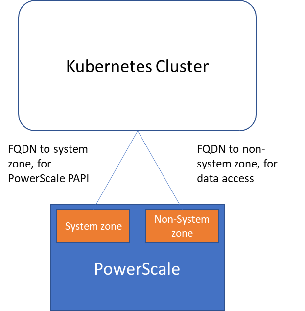
These two access zones are defined in different places in CSI configuration files:
- The PAPI access zone name (FQDN) needs to be set in the secret yaml file as “endpoint”, for example “f200.isilon.com”.
- The data access zone name (FQDN) needs to be set in the storageclass yaml file as “AzServiceIP”, for example “openshift-data.isilon.com”.
If an admin really cannot expose their System zone to the Kubernetes cluster, they have to disable the snapshot and quota features in the CSI installation configuration file (values.yaml). In this way, the PAPI access zone can be a non-System access zone.
The following diagram shows how the Kubernetes cluster connects to PowerScale access zones.
Network
Normally a Kubernetes cluster comes with many networks: a pod inter-communication network, a cluster service network, and so on. Luckily, the PowerScale network doesn’t have to join any of them. The CSI pods can access a host’s network directly, without going through the Kubernetes internal network. This also has the advantage of providing a dedicated high-performance network for data transfer.
For example, on a Kubernetes host, there are two NICs: IP 192.168.1.x and 172.24.1.x. NIC 192.168.1.x is used for Kubernetes, and is aligned with its hostname. NIC 172.24.1.x isn’t managed by Kubernetes. In this case, we can use NIC 172.24.1.x for data transfer between Kubernetes hosts and PowerScale.
Because by default, the CSI driver will use the IP that is aligned with its hostname, to let CSI recognize the second NIC 172.24.1.x, we have explicitly set the IP range in “allowedNetworks” in the values.yaml file in the CSI driver installation. For example:
allowedNetworks: [172.24.1.0/24]
Also, in this network configuration, it’s unlikely that the Kubernetes internal DNS can resolve the PowerScale FQDN. So, we also have to make sure the “dnsPolicy” has been set to “ClusterFirstWithHostNet” in the values.yaml file. With this dnsPolicy, the CSI pods will reach the DNS server in /etc/resolv.conf in the host OS, not the internal DNS server of Kubernetes.
The following diagram shows the configuration mentioned above:
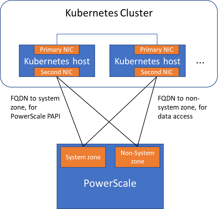
Please note that the “allowedNetworks” setting only affects the data access zone, and not the PAPI access zone. In fact, CSI just uses this parameter to decide which host IP should be set as the NFS client IP on the PowerScale side.
Regarding the network routing, CSI simply follows the OS route configuration. Because of that, if we want the PAPI access zone to go through the primary NIC (192.168.1.x), and have the data access zone to go through the second NIC (172.24.1.x), we have to change the route configuration of the Kubernetes host, not this parameter.
Hopefully this blog helps you understand the network configuration for PowerScale CSI better. Stay tuned for more information on Dell Containers & Storage!
Authors: Sean Zhan, Florian Coulombel