


Dell PowerFlex: Specification Sheet
Download PDFThe ultimate software-defined infrastructure
PowerFlex Family
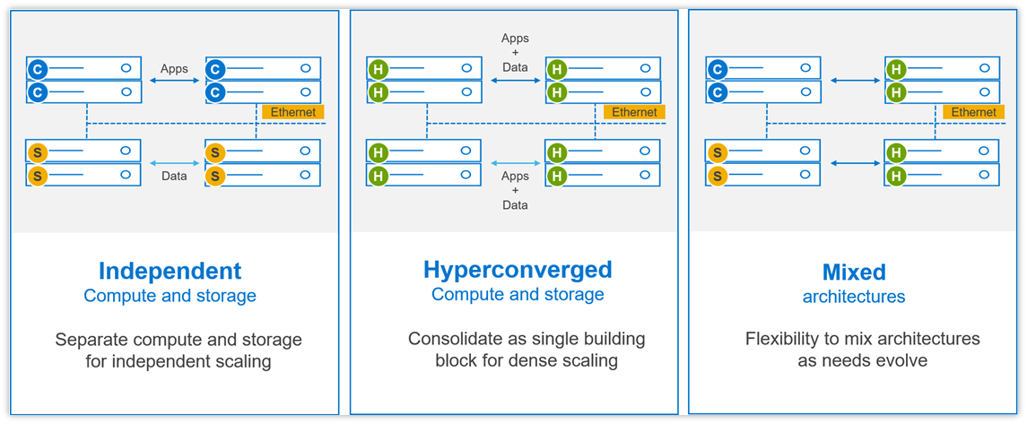
PowerFlex software-defined infrastructure enables broad consolidation across the data center, encompassing almost any type of workload and deployment topology. Its software-first architecture enables automation and programmability of the complete infrastructure stack. It provides scalability, performance, and resiliency, enabling effortless adherence to stringent workload SLAs. As a universal infrastructure platform, PowerFlex combines compute and high-performance software-defined storage resources in a managed, unified fabric for both block and file. Available in flexible consumption options (rack, appliance, custom nodes, or in the public cloud), it enables various deployment architectures: independent compute and storage (two-layer), HCI (single-layer), or a mixture of the two. PowerFlex is ideal for high performance applications and databases, building an agile private/hybrid cloud, or consolidating resources in heterogeneous environments. To learn about the business value and benefits organizations have achieved by using PowerFlex to run and manage their important business workloads, please read this white paper.
Selected Definitions
System – A PowerFlex system is the collection of entities managed by the Metadata Management (MDM) cluster.
MDM – Metadata Manager. A highly-available storage management cluster that resides alongside other software components within the system but sits outside the data path and supervises storage cluster health and configuration. It coordinates rebalancing and rebuilding/reprotecting data as changes occur in the system.
Protection Domain – A protection domain is a logical entity that consists of a group of SDSs that provide data protection for each other. Each SDS belongs to one (and only one) protection domain. By definition, each protection domain is a unique set of SDSs. Protection domains can be added during installation and modified post-installation.
Storage Pool - A storage pool is a set of physical storage devices within a protection domain. Each storage device belongs to one (and only one) storage pool. A volume is distributed over all devices residing in the same storage pool.
SDS – Storage Data Server. A software service, running on a node that contributes disks to the storage cluster. Working together, several SDSs abstract local storage, maintain storage pools, and present volumes to the SDCs. Each SDS node is a fault unit, and the distributed mesh-mirror copies of data are never placed on the same fault unit.
SDC – Storage Data Client. A client kernel driver that provides front-end volume access to operating systems, applications, or hypervisors. It presents PowerFlex volumes as local block devices. The SDC maintains peer-to-peer connections to every SDS managing a storage pool. It translates between the proprietary PowerFlex data transport protocol and block SCSI commands.
Device – Local, direct attached block storage (DAS) in a node that is managed by an SDS and is contributed to a storage pool.
Volume – Analogous to a LUN, a volume is a subset of a storage pool’s capacity presented by an SDC as a local block device. A volume’s data is evenly distributed across all disks comprising a storage pool, according to the data layout selected for that storage pool.
MG – A “medium granularity” data layout on the storage disks comprising a storage pool. This is the original storage pool option and provides very high performance.
FG - A “fine granularity” data layout on the storage disks comprising a storage pool. This storage pool option is designed for space efficiency, especially with heavy snapshot use. It requires the use of NVDIMMs and enables PowerFlex’s inline compression features.
Fault Set – A collection of SDSs that are managed together as a single fault unit. When employed, the distributed mesh-mirror copies of data are never placed within the same fault set.
SDR – Storage Data Replicator. A software service that lives alongside the SDS and other services and facilitates asynchronous replication activities between remote PowerFlex systems. The SDR implements journal shipping, coordinating both the collection of writes into source-side journals and the application of received writes to volumes on the target side.
SDT – Storage Data Target. Enables NVMe initiator clients to map and use PowerFlex volumes using the NVMe/TCP protocol. The SDT software service translates between the NVMe and proprietary PowerFlex protocols, supports discovery services, and manages client host connections.
System Limits
PowerFlex supports the following system limits in virtue of the software capabilities. Note that reaching some limits will preclude reaching others. (For example, although the max volume size is 1PB, creating very large volumes will preclude creating the max number of volumes in a Protection Domain – 32,768 – because the total size of all volumes in a storage pool is 4PB.) Under some configurations and consumption choices, these limits may differ due to the node, networking hardware, or management tools being employed.
For complete listing of product limits, look for the Dell PowerFlex 4.5.x Technical Overview at the link provided.
PowerFlex Item | Product Limit |
System Raw Capacity | 16 PB |
Device size | Minimum: 240 GB, Maximum: 8 TB (Maximum 15.36 TB for SSDs on medium granularity storage pools) |
Volume Size | Minimum: 8 GB, Maximum: 1 PB |
Maximum filesystem partitions per volume | 15 |
Maximum total number of volumes and snapshots in system | 131,072 a |
Maximum total number of volumes and snapshots in protection domain | 32,768 |
Maximum total number of volumes and snapshots per storage pool | 32,768 |
Maximum number of snapshots per source/root volume | 126 |
Maximum raw capacity per SDS | 160 TB (medium granularity) 128 TB (fine granularity) |
Maximum SDCs per system | 2048 |
Maximum SDSs per system | 512 a |
Maximum SDSs per protection domain | 128 a |
Maximum devices (drives) per SDS server | 64 (includes any NVDIMM devices) |
Maximum devices per protection domain | 8192 |
Maximum devices per storage pool | 300 |
Total size of all volumes per storage pool | 4PB |
Maximum volumes that can be mapped to a single SDC | 1024 |
System over provisioning factor | 5x net/usable capacity per MG layout |
Fine-granularity maximum compression | 10x raw capacity |
Maximum storage pools per system | 1024 |
Maximum storage pools per protection domain | 64 |
Maximum fault sets per protection domain | 64 |
Maximum Snapshot Policies per system | 1000 |
Maximum number of snapshots a snapshot policy can be defined to retain (not including locked snapshots) | 60 |
Maximum volumes per local Consistency Group (snapshot) | 1024 |
Maximum number of volume-to-SDC mappings per system | 262,143 |
Maximum user accounts | 256 |
Maximum number of concurrent logged-in management clients (GUI/REST/CLI) | 128 |
a If more are needed, contact Customer Support
Flexible Deployment Topologies
PowerFlex’s extreme flexibility meets the diverse and rapidly evolving needs of modern enterprises, offering unprecedented choice for customers to architect their mission-critical IT environments. Mix and match storage, compute, and HCI nodes in a dynamic deployment, scaling storage and compute resources together or independently, one node at a time, as needs dictate.
The functional character of a node is determined primarily by the installation/presence of software services running on a node. However, PowerFlex nodes are configured and purchased as “storage,” “compute,” or “HCI/hyperconverged” nodes. This reflects the type and quantity of resources in the node, ensuring that resources are suited to the expected usage. For example, storage nodes have less RAM and compute nodes usually have no capacity disks in them.
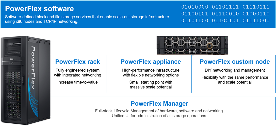
PowerFlex Consumption Options
With PowerFlex, you have choice and flexibility in how you choose to consume the PowerFlex architecture:
- PowerFlex rack is a fully engineered system with integrated networking. It is designed to simplify deployment and accelerate time to value.
- PowerFlex appliance is a flexible solution with a small starting point and massive scale potential. PowerFlex appliance provides a broad choice of supported networking with either full or partial network automation.
- PowerFlex custom nodes have the same performance and scale potential but leave the network management and hardware life-cycling up to the user.
- Public cloud – powering APEX Block Storage. This is a supported software-only deployment of the software-defined storage layer on recommended compute instances (with attached storage) in Amazon Web Services or Microsoft Azure. Only the MG data layout and “independent (2-layer)” block architectures are supported. Fault Sets may be used to distribute the cluster across multiple Availability Zones, thereby improving resiliency even to disruptions with an AZ. Native asynchronous replication may be used to migrate data between cloud and on-premises PowerFlex systems, or to establish cloud-based BC/DR data protection schemes.
PowerFlex is also available with OpEx-based consumption options with APEX Custom Solutions. Customers can choose between APEX Flex on Demand and APEX Datacenter Utility based on their unique requirements.
Node Options and Specifications
| PowerFlex R660 | PowerFlex R760 | PowerFlex R7625 | PowerFlex R6625 |
Chassis | 1 RU | 2 RU | 1 RU | |
CPU technology | 4th Gen Intel Xeon | 4th Gen AMD EPYC | ||
CPU sockets | Two | |||
CPU cores (total) | 16 - 112 | 32 - 192 | ||
CPU frequency | 1.8 GHz - 3.7 GHz | 2.20 GHz – 4.15 GHz | ||
RAM | 256GB - 4TB RDIMM | 256GB - 4TB RDIMM | ||
Maximum storage capacity (raw TB) | 76TB SAS 154TB* NVMe | 154TB* SAS 154TB* NVMe | diskless | |
Drive bays | 10 x 2.5” | 24 x 2.5” | diskless | |
Persistent memory | Yes | No | ||
Boot solution | 480GB (RAID1) “BOSS-N1” | |||
Nvidia GPU options | A2, L4 | H100, A100, A40, A30, A16, A2, L40, L4 | A2, L4 | |
Network connectivity (standard 4x25Gb) | Nvidia ConnectX-6 OCP and PCIe Broadcom 57414 OCP and PCIe | |||
Management port | iDRAC 9 Out of Band Management | |||
* PowerFlex version 4 or greater required for 154TB, otherwise maximum is 128TB
| PowerFlex R650 | PowerFlex R750 | PowerFlex R7525 | PowerFlex R6525 |
Chassis | 1 RU | 2 RU | 1 RU | |
CPU technology | 3rd Gen Intel Xeon | 3rd Gen AMD EPYC | ||
CPU sockets | Two | |||
CPU cores (total) | 16 - 80 | 16 - 128 | ||
CPU frequency | 2.00 GHz - 3.60 GHz | 2.00 GHz - 3.70 GHz | ||
RAM | 256 GB - 8 TB | 256 GB - 4 TB | ||
Maximum storage capacity (raw TB) | 76TB SAS 38TB SATA 154TB* NVMe | 154TB* SAS 92TB SATA 154TB* NVMe | diskless | |
Drive bays | 10 x 2.5” | 24 x 2.5” | diskless | |
NVDIMM support | Yes | No | ||
Boot solution | 480 GB SATA M.2 (RAID1) “BOSS-S2” | |||
Nvidia GPU options | A2, T4 | A100, A40, A30, A16, A10, A2, T4, L40 | A2, T4 | |
Network connectivity (standard 4x25Gb) | Nvidia ConnectX-5 OCP and PCIe Broadcom 57414 OCP and PCIe | |||
Management port | iDRAC 9 Out of Band Management | |||
* PowerFlex version 4 or greater required for 154TB, otherwise maximum is 128TB
| PowerFlex R640 | PowerFlex R740xd | PowerFlex R840 |
Chassis | 1 RU | 2 RU | |
CPU technology | 2nd Gen Intel Xeon | ||
CPU sockets | Two | Four | |
CPU cores (total) | 8 - 56 | 16 - 112 | |
CPU frequency | 2.1 GHz - 3.8 GHz | 2.1 GHz - 3.8 GHz | |
RAM | 96 GB - 3072 GB | 384 GB - 6144 GB | |
Maximum storage capacity (raw TB) | 76TB SAS 38TB SATA 76TB NVMe | 154TB* SAS 92TB SATA 154TB* NVMe | |
Drive bays | 10 x 2.5” | 24 x 2.5” | |
NVDIMM support | Yes† | Yes | |
Boot solution | 240 GB SATA M.2 (RAID1) “BOSS” | ||
Nvidia GPU options | T4 | A100, A40, A30, A16, A10, T4 | - |
Network connectivity (standard 4x25Gb) | Mellanox ConnectX-4 rNDC Mellanox ConnectX-4 Mellanox ConnectX-6 | ||
Management port | iDRAC 9 Out of Band Management | ||
* PowerFlex version 4 or greater required for 154TB, otherwise maximum is 128TB
† R640 does not support both NVMe and NVDIMM together
Consolidation: OS, Hypervisor, Platform Support
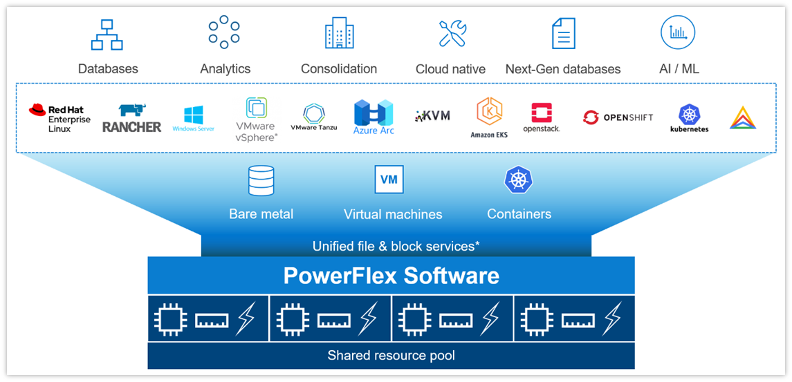
The platform supports a broad range of operating environments – bare metal operating systems, hypervisors, and container platforms – simultaneously with a unified infrastructure platform and management. By allowing users to flexibly mix these architectures in a single deployment, PowerFlex enables you to deploy, scale, and evolve all your applications to meet your business objectives.
Selected OS/Hypervisor Support
PowerFlex Item | Product Support |
Storage Data Client | ESXi 6.7, ESXi-7.0 ESXi 7.0 Update 3f (minimum for NVMe/TCP) Windows Server 2016, 2019, 2022 + Hyper-V XenServer 7.x CU2 LTSR Citrix Hypervisor 8.x RHEL 7.9, 8.4, 8.5, 8.6, 8.7, 8.8, 9.0, 9.1, 9.2 CentOS 7.9, CentOS Stream 8.x, Stream 9.x SLES 12 SP5, 15 SP3, 15 SP4, 15 SP5 Oracle Linux 7.9, 8.5, 8.6, 8.7, 8.8, 9.0, 9.1, 9.2 – with RH or UEK Kernels (+ KVM) IBM AIX 7.2 TL5, IBM AIX 7.3 TL0 Ubuntu 18.04.6 LTS and earlier Ubuntu 20.04.2 LTS and earlier RHEL CoreOS (when using PowerFlex SDC container for CSI driver) |
Storage Data Server | ESXi 6.7 and 7.0* (only with PowerFlex Manager – rack and appliance) RHEL 7.9, 8.4, 8.5, 8.6, 8.7, 8.8, 9.0, 9.1, 9.2 CentOS 7.9, CentOS Stream 8.x, Stream 9.x SLES 12 SP5, 15 SP3, 15 SP4, 15 SP5 PowerFlex EmbeddedOS (Linux)* Oracle Linux 7.9, 8.5, 8.6, 8.7, 8.8, 9.0, 9.1, 9.2 – with RH or UEK Kernels (+ KVM) Ubuntu 18.04.6 LTS and earlier Ubuntu 20.04.2 LTS and earlier |
* Only ESXi 7 and the PowerFlex EmbeddedOS are fully managed and life-cycled by PowerFlex Manager
PowerFlex Software Features and Functions
PowerFlex offers many enterprise data services. For example:
- Snapshots – read/write or read-only snapshots; snapshot scheduling; and secure/immutable snapshots.
- Compression – inline compression is enabled when using the fine-granularity data layout for storage pools.
- Native Asynchronous Replication – PowerFlex includes native async replication capabilities between PowerFlex clusters – up to 5 in any arbitrary topology. Note: individual volumes are replicated to only 1 target.
PowerFlex Replication Item | Product Limit |
Number of destination systems for replication | 4 |
Maximum number of SDR per system | 128 |
Maximum number of Replication Consistency Group (RCG) | 1024 |
Maximum number of Volume Pairs per RCG | 1024 |
Maximum replicated Volume Pairs per system | 32,000 |
Maximum number of remote protection domains | 8 |
Maximum number of copies per RCG | 1 |
Recovery Point Objective (RPO) | Minimum: 15 seconds, Maximum: 1 hour |
Maximum replicated volume size | 64 TB |
PowerFlex File Services
PowerFlex File Services run on a set of PowerFlex File Controllers. PowerFlex File Controller nodes, also known as File Nodes, are diskless nodes that are clustered together and host the NAS Server containers. The NAS Servers in turn host the tenant namespaces, with their individual security policies and file systems. The File Controller Nodes extend the functionality of a PowerFlex cluster that supplies the underlying block storage. A PowerFlex volume is mapped to each file system that is presented by the NAS Servers. The volumes, and thus the NAS filesystems, may be dynamically scaled in the background. In-line compression is supported when the volume storage pool is FG. All major protocols are supported.
New in 4.5, multiple NAS servers can be brought together under a Global Namespace, allowing for over 8PB of filesystem space to be shared via SMB (with DFS), NFS v4, or both, though a single IP address and namespace.
PowerFlex Item | Product Limit | New in 4.5 |
Maximum NAS cluster size (number of nodes) | 16 (must be an even number) |
|
Minimum NAS cluster size (number of nodes) | 2 |
|
Maximum file system size | 256 TB (Minimum 8 GB) |
|
Maximum number of file systems | 4,096 (256*16N) | 16,384 (1024*16N) |
Maximum number of NAS servers | 512 | 2048 |
Maximum file snapshots | 2,500 | 57,000 |
Maximum number of file systems per NAS server | 125 |
|
Maximum number of file systems plus mounted snaps per NAS server | 1,500 |
|
Maximum NFS servers per system | 512 |
|
Maximum SMB servers per system | 512 |
|
Maximum SMB shares per node | 10,000 |
|
Maximum SMB shares per system | 160,000 |
|
Maximum NFS exports per node | 5,000 |
|
Maximum NFS exports per system | 80,000 |
|
Maximum tree quotas per file system | 8,191 |
|
Maximum file names per directory | 10 million |
|
Maximum sub-directories/files per directory | 10 million |
|
Maximum number of home directories | 40,000 |
|
Maximum SMB TCP connections | 128,000 |
|
Maximum NFS TCP connections | 128,000 |
|
Maximum TCP connections per system | 153,600 |
|
Maximum unique ACLs per file system | 4 million |
|
Maximum directories per file system | > 10 billion |
|
Maximum open files/directories | 512,000 |
|
Maximum files per file system | 32 billion |
|
PowerFlex File Features
Feature | Description |
Supported Protocols | NFS v3/v4, SMB (CIFS) v2/v3, FTP, SFTP, and NDMP |
File System Operations | User quotas and Tree quotas Extend/shrink file system (space reclaim) File system read/write snapshots Single / Global Namespace option |
Data Reduction | Inline compression when used with FG storage pools |
Data Protection | 3-way NMDP support for backup |
Security | CAVA - Common Antivirus Agent for SMB Clients CEPA - Common Event Publishing Agent (version 4.5+) D@RE with PowerFlex Enterprise Encryption and KeyStore |
Serviceability | SRS/ESE (Call Home) Alerts Data collection aka “native audit log” |
Management and Monitoring | UI and REST API CloudIQ Integration SNMP v2 and v3 support |
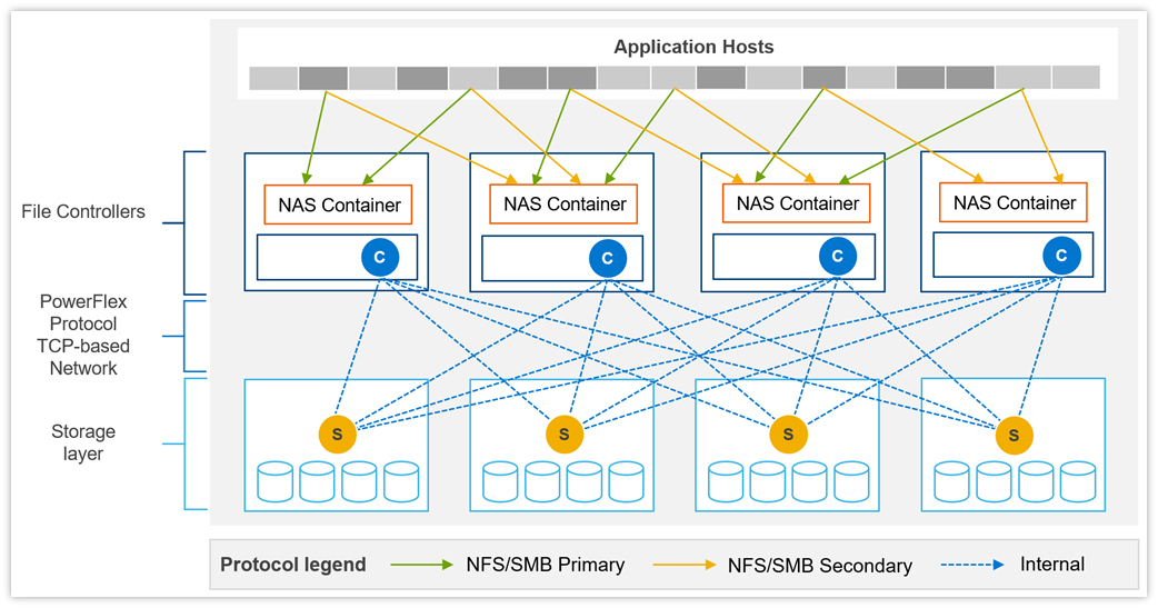
Example of data path communication between clients, NAS servers, and block storage backend.
File Controller Node Options
Component | Model | CPU | Cores | RAM(GB) | NIC (GbE) | Local Storage (GB) |
Small Node | PowerFlex R650S | Intel Xeon 2x5317 | 2x12 (24) | 128 | 4 x 25 | 480GB BOSS M.2 |
Medium Node | PowerFlex R650M | Intel Xeon 2x6346 | 2x16 (32) | 256 | 4 x 25 | 480GB BOSS M.2 |
Large Node | PowerFlex R650L | Intel Xeon 2x6348 | 2x28 (56) | 256 | 4 x 25 | 480GB BOSS M.2 |
Data Access Protocols
In addition to the file access protocols, listed above, PowerFlex supports two block protocols. The primary transport protocol is a proprietary TCP-based protocol that efficiently moves data between the Storage Data Servers (SDSs) and Storage Data Clients (SDCs), as well as among the contributing SDSs. The architecture includes native multipathing between the SDC and all SDSs that host volume data. The SDC translates this to a subset of the standard SCSI commands, for consumption by operating systems, hypervisors, and applications that can access raw block devices.
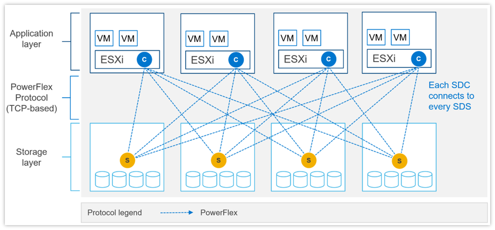 Example of SDC – SDS communication with SDC installed in ESXi.
PowerFlex 4.0 also introduced support for NVMe/TCP, allowing for the consumption of PowerFlex volumes without installing the proprietary kernel driver. Support for NVMe/TCP is facilitated by the Storage Data Target (SDT) service, which runs on nodes also running the SDS service. The SDT translates between the system’s native PowerFlex protocol and NVMe commands. It also functions as a discovery service for client initiators.
NVMe/TCP requires kernels that contain native support for the protocol. In VMware, this is ESXi 7.0 Update 3f or later. It is also available as a Tech Preview in supported Linux Distributions: RHEL 8.6 and later, SLES 15 SP3 and later, Ubuntu 22.04.
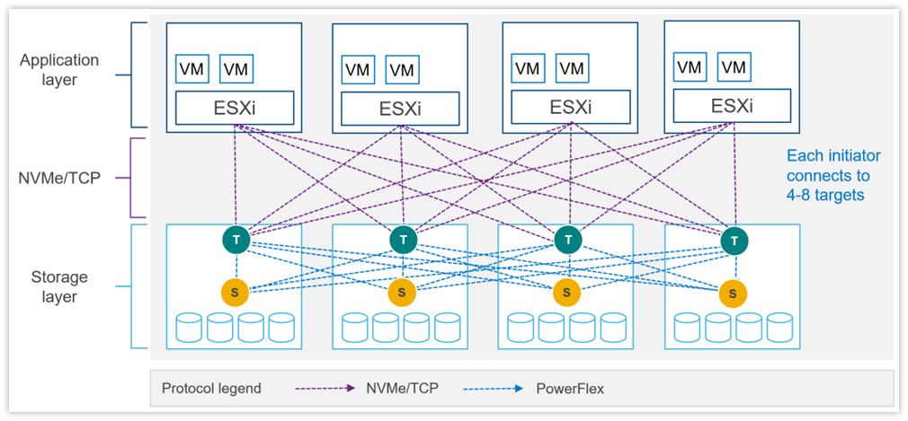 Example of NVMe/TCP communication with PowerFlex storage with ESXi.
NVMe/TCP Limits
PowerFlex Item | Product Limit |
Maximum volumes mapped to a single NVMe host (Linux) | 1024 |
Maximum volumes mapped to a single NVMe host (ESXi) | 32 (in ESXi 7.0) 256 (in ESXi 8.0) |
Maximum NVMe hosts connected to system | 1024 (included in total SDCs per system) |
Maximum SDTs per protection domain | 128 |
Minimum SDTs per protection domain | 2* |
Maximum SDTs per system | 512 |
Maximum paths in multipathing driver per volume | 8 (in ESXi 7.0u3) 32 (in ESXi 8.0u1) |
Maximum connections per host per protection domain | 16 |
Maximum NVMe host connections (I/O controllers) per SDT | 512 |
Maximum NVMe host connections (I/O controllers) per system | 65,519 |
Maximum I/O controller queue depth | 128† |
Maximum I/O controller queues | 32† |
Maximum volume-to-host mappings (SDC/NVMe) per system | 262,143 |
* Using minimum SDTs may block the ability to reach maximum NVMe hosts.
† Number of queues + queue depth is automatically negotiated on connection.
PowerFlex Manager (PFxM)
PowerFlex Manager is the M&O software layer that further enables ITOM automation and LCM capabilities for hardware and networking. Starting with PowerFlex 4.0, the unified PowerFlex Manager brings together three separate components used in previous releases – PowerFlex Manager, the core PowerFlex UI, and the PowerFlex gateway UI. The new PowerFlex Manager and UI runs as containerized services in a distributed Kubernetes platform
PowerFlex Manager offers standards-based open APIs and custom Ansible modules, making it simple to integrate with third party tools and custom workflows. Further, when paired with Dell CloudIQ, PowerFlex leverages an AI/ML-based approach to infrastructure monitoring and management, ensuring simplicity and consistency at scale.
PowerFlex Clustering, Scaling and Management | ||
Min Nodes Per Cluster (Two-layer Configuration) | 4 Storage Only nodes minimum (6 or more recommended) 1 to 3 Compute Only nodes (depending on host OS) | |
Min Nodes Per Cluster (HCI Configuration) | 4 HCI Nodes minimum (6 or more recommended) | |
Scaling Increments | 1 Node (HCI, Compute Only or Storage Only) † | |
PowerFlex Management Node Requirements‡ |
EmbeddedOS Jump Server Secure Connect Gateway PowerFlex Management VMs (3x) PowerFlex Enterprise Encryption and KeyStore (optional) |
16GB RAM, 4 vCPU, 500GB storage 4GB RAM, 2 vCPU, 16GB storage 32GB RAM, 16 vCPU, 650GB storage (each)
6GB RAM, 4 vCPU, 64GB storage |
(Supplied as virtual machine images) | ||
* In 2-layer environments where existing compute nodes are to be utilized or compute nodes are running an operating system not supported by PowerFlex Manager, the minimum requirement is for four storage nodes only.
† A single node is the minimum scaling required to expand an existing Storage Pool. Creation of a net new Storage Pool requires the addition of a minimum of 3 Storage or HCI Nodes.
‡ New PowerFlex appliance deployments include a single-node management controller (with an option for three-node for larger systems). New PowerFlex integrated rack deployments include a three-node or four-node management controller cluster. These PowerFlex Management Controller options are ESXi based.
PowerFlex Manager: Supported Switches
PowerFlex Manager Supported Switches | |
Management Switches* | Cisco Nexus 3172TQ, Cisco Nexus 31108TC-V, Cisco Nexus 92348GC-X, |
Access or Leaf Switches | Cisco Nexus 3132QX, Cisco Nexus 3164Q, Cisco Nexus 93180YC-EX, |
Aggregation or Spine Switches | Cisco Nexus 9236C, Cisco Nexus 9336C-FX2, Cisco Nexus 9364C-GX, Cisco Nexus 9364C-GX, Dell S5232F-ON |
* For PowerFlex appliance, the management switch can be “bring your own”.
‡ Appliance only
Power and Dimensions
| PowerFlex R660 | PowerFlex R760 | PowerFlex R6625 | PowerFlex R7625 | |
Fully redundant power supplies (100-240Vac) | 700 W Titanium 800 W Platinum 1100 W Titanium 1400 W Platinum 1800 W Titanium | 700 W Titanium 800 W Platinum 1400 W Platinum 1800 W Titanium 2400 W Platinum 2800 W Titanium | 700 W Titanium 800 W Platinum 1100 W Titanium 1400 W Platinum 1800 W Titanium | 700 W Titanium 800 W Platinum 1400 W Platinum 1800 W Titanium 2400 W Platinum 2800 W Titanium | |
Redundant cooling fans | 8 | 6 | 8 | 6 | |
Physical dimensions | H W D Wgt | 42.8 mm 434 mm 823 mm 21.2 kg | 86.8 mm 434 mm 772 mm 35.3 kg | 42.8 mm 434 mm 751 mm 21.2 kg | 86.8 mm 434 mm 700 mm 24.6 kg |
| PowerFlex R650 | PowerFlex R750 | PowerFlex R6525 | PowerFlex R7525 | |
Fully redundant power supplies (100-240Vac) | 800 W 1100 W 1400 W 1100 W (48-60Vdc) | 800 W 1100 W 1400 W 2400 W | 800 W 1100 W 1400 W 1100 W (48-60Vdc) | 1100 W 1400 W 2400 W | |
Redundant cooling fans | 8 | 6 | 8 | 6 | |
Physical dimensions | H W D Wgt | 42.8 mm 434 mm 751 mm 21.2 kg | 86.8 mm 434 mm 700 mm 35.3 kg | 42.8 mm 434 mm 751 mm 21.2 kg | 86.8 mm 434 mm 700 mm 24.6 kg |
| PowerFlex R640 | PowerFlex R740xd | PowerFlex R840 | |
Fully redundant power supplies (100-240Vac) | 750 W 1100 W 1600 W 1100 W (48Vdc) | 1100 W 1600 W 2000 W 2400 W | 1600 W 2000 W 2400 W | |
Redundant cooling fans | 8 | 6 | 6 | |
Physical dimensions | H W D Wgt | 42.8 mm 434 mm 734 mm 21.9 kg | 86.8 mm 434 mm 679 mm 28.1 kg | 86.8 mm 434 mm 679 mm 28.1 kg |
Environmental and Certificates
| PowerFlex R660 | PowerFlex R760 | PowerFlex R6625 | PowerFlex R7625 |
Ambient operating temperature (A2) | 10°C to 35°C | 10°C to 35°C | 10°C to 35°C | 10°C to 35°C |
Storage temperature range | -40°C to 65°C | -40°C to 65°C | -40°C to 65°C | -40°C to 65°C |
Operating relative humidity (non-condensing) | 8% to 80% | 8% to 80% | 8% to 80% | 8% to 80% |
Operating altitude with no deratings | 3048m | 3048m | 3048m | 3048m |
| PowerFlex R650 | PowerFlex R750 | PowerFlex R6525 | PowerFlex R7525 |
Ambient operating temperature (A2) | 10°C to 35°C | 10°C to 35°C | 10°C to 35°C | 10°C to 35°C |
Storage temperature range | -40°C to 65°C | -40°C to 65°C | -40°C to 65°C | -40°C to 65°C |
Operating relative humidity (non-condensing) | 8% to 80% | 8% to 80% | 8% to 80% | 8% to 80% |
Operating altitude with no deratings | 3048m | 3048m | 3048m | 3048m |
| PowerFlex R640 | PowerFlex R740xd | PowerFlex R840 |
Ambient operating temperature (A2) | 10°C to 35°C | 10°C to 35°C | 10°C to 35°C |
Storage temperature range | -40°C to 65°C | -40°C to 65°C | -40°C to 65°C |
Operating relative humidity (non-condensing) | 10% to 80% | 10% to 80% | 10% to 80% |
Operating altitude with no deratings | 3048m | 3048m | 3048m |
Statement of Compliance
Dell Information Technology Equipment is compliant with all currently applicable regulatory requirements for Electromagnetic Compatibility, Product Safety, and Environmental Regulations where placed on market.
Detailed regulatory information and verification of compliance is available at the Dell Regulatory Compliance website.
https://www.dell.com/REGULATORY_COMPLIANCE