
Assets

Dell PowerFlex: Specification Sheet
Mon, 04 Mar 2024 22:19:46 -0000
|Read Time: 0 minutes
The ultimate software-defined infrastructure
PowerFlex Family
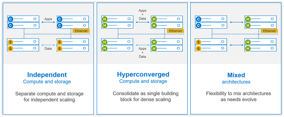
PowerFlex software-defined infrastructure enables broad consolidation across the data center, encompassing almost any type of workload and deployment topology. Its software-first architecture enables automation and programmability of the complete infrastructure stack. It provides scalability, performance, and resiliency, enabling effortless adherence to stringent workload SLAs. As a universal infrastructure platform, PowerFlex combines compute and high-performance software-defined storage resources in a managed, unified fabric for both block and file. Available in flexible consumption options (rack, appliance, custom nodes, or in the public cloud), it enables various deployment architectures: independent compute and storage (two-layer), HCI (single-layer), or a mixture of the two. PowerFlex is ideal for high performance applications and databases, building an agile private/hybrid cloud, or consolidating resources in heterogeneous environments. To learn about the business value and benefits organizations have achieved by using PowerFlex to run and manage their important business workloads, please read this white paper.
Selected Definitions
System – A PowerFlex system is the collection of entities managed by the Metadata Management (MDM) cluster.
MDM – Metadata Manager. A highly-available storage management cluster that resides alongside other software components within the system but sits outside the data path and supervises storage cluster health and configuration. It coordinates rebalancing and rebuilding/reprotecting data as changes occur in the system.
Protection Domain – A protection domain is a logical entity that consists of a group of SDSs that provide data protection for each other. Each SDS belongs to one (and only one) protection domain. By definition, each protection domain is a unique set of SDSs. Protection domains can be added during installation and modified post-installation.
Storage Pool - A storage pool is a set of physical storage devices within a protection domain. Each storage device belongs to one (and only one) storage pool. A volume is distributed over all devices residing in the same storage pool.
SDS – Storage Data Server. A software service, running on a node that contributes disks to the storage cluster. Working together, several SDSs abstract local storage, maintain storage pools, and present volumes to the SDCs. Each SDS node is a fault unit, and the distributed mesh-mirror copies of data are never placed on the same fault unit.
SDC – Storage Data Client. A client kernel driver that provides front-end volume access to operating systems, applications, or hypervisors. It presents PowerFlex volumes as local block devices. The SDC maintains peer-to-peer connections to every SDS managing a storage pool. It translates between the proprietary PowerFlex data transport protocol and block SCSI commands.
Device – Local, direct attached block storage (DAS) in a node that is managed by an SDS and is contributed to a storage pool.
Volume – Analogous to a LUN, a volume is a subset of a storage pool’s capacity presented by an SDC as a local block device. A volume’s data is evenly distributed across all disks comprising a storage pool, according to the data layout selected for that storage pool.
MG – A “medium granularity” data layout on the storage disks comprising a storage pool. This is the original storage pool option and provides very high performance.
FG - A “fine granularity” data layout on the storage disks comprising a storage pool. This storage pool option is designed for space efficiency, especially with heavy snapshot use. It requires the use of NVDIMMs and enables PowerFlex’s inline compression features.
Fault Set – A collection of SDSs that are managed together as a single fault unit. When employed, the distributed mesh-mirror copies of data are never placed within the same fault set.
SDR – Storage Data Replicator. A software service that lives alongside the SDS and other services and facilitates asynchronous replication activities between remote PowerFlex systems. The SDR implements journal shipping, coordinating both the collection of writes into source-side journals and the application of received writes to volumes on the target side.
SDT – Storage Data Target. Enables NVMe initiator clients to map and use PowerFlex volumes using the NVMe/TCP protocol. The SDT software service translates between the NVMe and proprietary PowerFlex protocols, supports discovery services, and manages client host connections.
System Limits
PowerFlex supports the following system limits in virtue of the software capabilities. Note that reaching some limits will preclude reaching others. (For example, although the max volume size is 1PB, creating very large volumes will preclude creating the max number of volumes in a Protection Domain – 32,768 – because the total size of all volumes in a storage pool is 4PB.) Under some configurations and consumption choices, these limits may differ due to the node, networking hardware, or management tools being employed.
For complete listing of product limits, look for the Dell PowerFlex 4.5.x Technical Overview at the link provided.
PowerFlex Item | Product Limit |
System Raw Capacity | 16 PB |
Device size | Minimum: 240 GB, Maximum: 8 TB (Maximum 15.36 TB for SSDs on medium granularity storage pools) |
Volume Size | Minimum: 8 GB, Maximum: 1 PB |
Maximum filesystem partitions per volume | 15 |
Maximum total number of volumes and snapshots in system | 131,072 a |
Maximum total number of volumes and snapshots in protection domain | 32,768 |
Maximum total number of volumes and snapshots per storage pool | 32,768 |
Maximum number of snapshots per source/root volume | 126 |
Maximum raw capacity per SDS | 160 TB (medium granularity) 128 TB (fine granularity) |
Maximum SDCs per system | 2048 |
Maximum SDSs per system | 512 a |
Maximum SDSs per protection domain | 128 a |
Maximum devices (drives) per SDS server | 64 (includes any NVDIMM devices) |
Maximum devices per protection domain | 8192 |
Maximum devices per storage pool | 300 |
Total size of all volumes per storage pool | 4PB |
Maximum volumes that can be mapped to a single SDC | 1024 |
System over provisioning factor | 5x net/usable capacity per MG layout |
Fine-granularity maximum compression | 10x raw capacity |
Maximum storage pools per system | 1024 |
Maximum storage pools per protection domain | 64 |
Maximum fault sets per protection domain | 64 |
Maximum Snapshot Policies per system | 1000 |
Maximum number of snapshots a snapshot policy can be defined to retain (not including locked snapshots) | 60 |
Maximum volumes per local Consistency Group (snapshot) | 1024 |
Maximum number of volume-to-SDC mappings per system | 262,143 |
Maximum user accounts | 256 |
Maximum number of concurrent logged-in management clients (GUI/REST/CLI) | 128 |
a If more are needed, contact Customer Support
Flexible Deployment Topologies
PowerFlex’s extreme flexibility meets the diverse and rapidly evolving needs of modern enterprises, offering unprecedented choice for customers to architect their mission-critical IT environments. Mix and match storage, compute, and HCI nodes in a dynamic deployment, scaling storage and compute resources together or independently, one node at a time, as needs dictate.
The functional character of a node is determined primarily by the installation/presence of software services running on a node. However, PowerFlex nodes are configured and purchased as “storage,” “compute,” or “HCI/hyperconverged” nodes. This reflects the type and quantity of resources in the node, ensuring that resources are suited to the expected usage. For example, storage nodes have less RAM and compute nodes usually have no capacity disks in them.
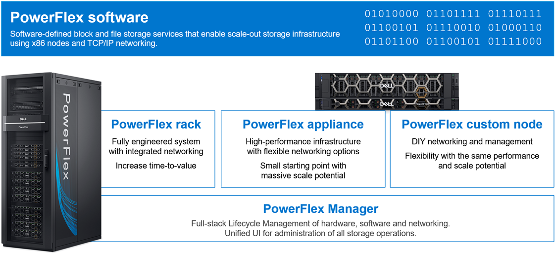
PowerFlex Consumption Options
With PowerFlex, you have choice and flexibility in how you choose to consume the PowerFlex architecture:
- PowerFlex rack is a fully engineered system with integrated networking. It is designed to simplify deployment and accelerate time to value.
- PowerFlex appliance is a flexible solution with a small starting point and massive scale potential. PowerFlex appliance provides a broad choice of supported networking with either full or partial network automation.
- PowerFlex custom nodes have the same performance and scale potential but leave the network management and hardware life-cycling up to the user.
- Public cloud – powering APEX Block Storage. This is a supported software-only deployment of the software-defined storage layer on recommended compute instances (with attached storage) in Amazon Web Services or Microsoft Azure. Only the MG data layout and “independent (2-layer)” block architectures are supported. Fault Sets may be used to distribute the cluster across multiple Availability Zones, thereby improving resiliency even to disruptions with an AZ. Native asynchronous replication may be used to migrate data between cloud and on-premises PowerFlex systems, or to establish cloud-based BC/DR data protection schemes.
PowerFlex is also available with OpEx-based consumption options with APEX Custom Solutions. Customers can choose between APEX Flex on Demand and APEX Datacenter Utility based on their unique requirements.
Node Options and Specifications
| PowerFlex R660 | PowerFlex R760 | PowerFlex R7625 | PowerFlex R6625 |
Chassis | 1 RU | 2 RU | 1 RU | |
CPU technology | 4th Gen Intel Xeon | 4th Gen AMD EPYC | ||
CPU sockets | Two | |||
CPU cores (total) | 16 - 112 | 32 - 192 | ||
CPU frequency | 1.8 GHz - 3.7 GHz | 2.20 GHz – 4.15 GHz | ||
RAM | 256GB - 4TB RDIMM | 256GB - 4TB RDIMM | ||
Maximum storage capacity (raw TB) | 76TB SAS 154TB* NVMe | 154TB* SAS 154TB* NVMe | diskless | |
Drive bays | 10 x 2.5” | 24 x 2.5” | diskless | |
Persistent memory | Yes | No | ||
Boot solution | 480GB (RAID1) “BOSS-N1” | |||
Nvidia GPU options | A2, L4 | H100, A100, A40, A30, A16, A2, L40, L4 | A2, L4 | |
Network connectivity (standard 4x25Gb) | Nvidia ConnectX-6 OCP and PCIe Broadcom 57414 OCP and PCIe | |||
Management port | iDRAC 9 Out of Band Management | |||
* PowerFlex version 4 or greater required for 154TB, otherwise maximum is 128TB
| PowerFlex R650 | PowerFlex R750 | PowerFlex R7525 | PowerFlex R6525 |
Chassis | 1 RU | 2 RU | 1 RU | |
CPU technology | 3rd Gen Intel Xeon | 3rd Gen AMD EPYC | ||
CPU sockets | Two | |||
CPU cores (total) | 16 - 80 | 16 - 128 | ||
CPU frequency | 2.00 GHz - 3.60 GHz | 2.00 GHz - 3.70 GHz | ||
RAM | 256 GB - 8 TB | 256 GB - 4 TB | ||
Maximum storage capacity (raw TB) | 76TB SAS 38TB SATA 154TB* NVMe | 154TB* SAS 92TB SATA 154TB* NVMe | diskless | |
Drive bays | 10 x 2.5” | 24 x 2.5” | diskless | |
NVDIMM support | Yes | No | ||
Boot solution | 480 GB SATA M.2 (RAID1) “BOSS-S2” | |||
Nvidia GPU options | A2, T4 | A100, A40, A30, A16, A10, A2, T4, L40 | A2, T4 | |
Network connectivity (standard 4x25Gb) | Nvidia ConnectX-5 OCP and PCIe Broadcom 57414 OCP and PCIe | |||
Management port | iDRAC 9 Out of Band Management | |||
* PowerFlex version 4 or greater required for 154TB, otherwise maximum is 128TB
| PowerFlex R640 | PowerFlex R740xd | PowerFlex R840 |
Chassis | 1 RU | 2 RU | |
CPU technology | 2nd Gen Intel Xeon | ||
CPU sockets | Two | Four | |
CPU cores (total) | 8 - 56 | 16 - 112 | |
CPU frequency | 2.1 GHz - 3.8 GHz | 2.1 GHz - 3.8 GHz | |
RAM | 96 GB - 3072 GB | 384 GB - 6144 GB | |
Maximum storage capacity (raw TB) | 76TB SAS 38TB SATA 76TB NVMe | 154TB* SAS 92TB SATA 154TB* NVMe | |
Drive bays | 10 x 2.5” | 24 x 2.5” | |
NVDIMM support | Yes† | Yes | |
Boot solution | 240 GB SATA M.2 (RAID1) “BOSS” | ||
Nvidia GPU options | T4 | A100, A40, A30, A16, A10, T4 | - |
Network connectivity (standard 4x25Gb) | Mellanox ConnectX-4 rNDC Mellanox ConnectX-4 Mellanox ConnectX-6 | ||
Management port | iDRAC 9 Out of Band Management | ||
* PowerFlex version 4 or greater required for 154TB, otherwise maximum is 128TB
† R640 does not support both NVMe and NVDIMM together
Consolidation: OS, Hypervisor, Platform Support
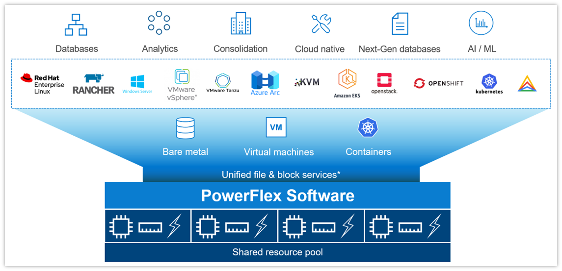
The platform supports a broad range of operating environments – bare metal operating systems, hypervisors, and container platforms – simultaneously with a unified infrastructure platform and management. By allowing users to flexibly mix these architectures in a single deployment, PowerFlex enables you to deploy, scale, and evolve all your applications to meet your business objectives.
Selected OS/Hypervisor Support
PowerFlex Item | Product Support |
Storage Data Client | ESXi 6.7, ESXi-7.0 ESXi 7.0 Update 3f (minimum for NVMe/TCP) Windows Server 2016, 2019, 2022 + Hyper-V XenServer 7.x CU2 LTSR Citrix Hypervisor 8.x RHEL 7.9, 8.4, 8.5, 8.6, 8.7, 8.8, 9.0, 9.1, 9.2 CentOS 7.9, CentOS Stream 8.x, Stream 9.x SLES 12 SP5, 15 SP3, 15 SP4, 15 SP5 Oracle Linux 7.9, 8.5, 8.6, 8.7, 8.8, 9.0, 9.1, 9.2 – with RH or UEK Kernels (+ KVM) IBM AIX 7.2 TL5, IBM AIX 7.3 TL0 Ubuntu 18.04.6 LTS and earlier Ubuntu 20.04.2 LTS and earlier RHEL CoreOS (when using PowerFlex SDC container for CSI driver) |
Storage Data Server | ESXi 6.7 and 7.0* (only with PowerFlex Manager – rack and appliance) RHEL 7.9, 8.4, 8.5, 8.6, 8.7, 8.8, 9.0, 9.1, 9.2 CentOS 7.9, CentOS Stream 8.x, Stream 9.x SLES 12 SP5, 15 SP3, 15 SP4, 15 SP5 PowerFlex EmbeddedOS (Linux)* Oracle Linux 7.9, 8.5, 8.6, 8.7, 8.8, 9.0, 9.1, 9.2 – with RH or UEK Kernels (+ KVM) Ubuntu 18.04.6 LTS and earlier Ubuntu 20.04.2 LTS and earlier |
* Only ESXi 7 and the PowerFlex EmbeddedOS are fully managed and life-cycled by PowerFlex Manager
PowerFlex Software Features and Functions
PowerFlex offers many enterprise data services. For example:
- Snapshots – read/write or read-only snapshots; snapshot scheduling; and secure/immutable snapshots.
- Compression – inline compression is enabled when using the fine-granularity data layout for storage pools.
- Native Asynchronous Replication – PowerFlex includes native async replication capabilities between PowerFlex clusters – up to 5 in any arbitrary topology. Note: individual volumes are replicated to only 1 target.
PowerFlex Replication Item | Product Limit |
Number of destination systems for replication | 4 |
Maximum number of SDR per system | 128 |
Maximum number of Replication Consistency Group (RCG) | 1024 |
Maximum number of Volume Pairs per RCG | 1024 |
Maximum replicated Volume Pairs per system | 32,000 |
Maximum number of remote protection domains | 8 |
Maximum number of copies per RCG | 1 |
Recovery Point Objective (RPO) | Minimum: 15 seconds, Maximum: 1 hour |
Maximum replicated volume size | 64 TB |
PowerFlex File Services
PowerFlex File Services run on a set of PowerFlex File Controllers. PowerFlex File Controller nodes, also known as File Nodes, are diskless nodes that are clustered together and host the NAS Server containers. The NAS Servers in turn host the tenant namespaces, with their individual security policies and file systems. The File Controller Nodes extend the functionality of a PowerFlex cluster that supplies the underlying block storage. A PowerFlex volume is mapped to each file system that is presented by the NAS Servers. The volumes, and thus the NAS filesystems, may be dynamically scaled in the background. In-line compression is supported when the volume storage pool is FG. All major protocols are supported.
New in 4.5, multiple NAS servers can be brought together under a Global Namespace, allowing for over 8PB of filesystem space to be shared via SMB (with DFS), NFS v4, or both, though a single IP address and namespace.
PowerFlex Item | Product Limit | New in 4.5 |
Maximum NAS cluster size (number of nodes) | 16 (must be an even number) |
|
Minimum NAS cluster size (number of nodes) | 2 |
|
Maximum file system size | 256 TB (Minimum 8 GB) |
|
Maximum number of file systems | 4,096 (256*16N) | 16,384 (1024*16N) |
Maximum number of NAS servers | 512 | 2048 |
Maximum file snapshots | 2,500 | 57,000 |
Maximum number of file systems per NAS server | 125 |
|
Maximum number of file systems plus mounted snaps per NAS server | 1,500 |
|
Maximum NFS servers per system | 512 |
|
Maximum SMB servers per system | 512 |
|
Maximum SMB shares per node | 10,000 |
|
Maximum SMB shares per system | 160,000 |
|
Maximum NFS exports per node | 5,000 |
|
Maximum NFS exports per system | 80,000 |
|
Maximum tree quotas per file system | 8,191 |
|
Maximum file names per directory | 10 million |
|
Maximum sub-directories/files per directory | 10 million |
|
Maximum number of home directories | 40,000 |
|
Maximum SMB TCP connections | 128,000 |
|
Maximum NFS TCP connections | 128,000 |
|
Maximum TCP connections per system | 153,600 |
|
Maximum unique ACLs per file system | 4 million |
|
Maximum directories per file system | > 10 billion |
|
Maximum open files/directories | 512,000 |
|
Maximum files per file system | 32 billion |
|
PowerFlex File Features
Feature | Description |
Supported Protocols | NFS v3/v4, SMB (CIFS) v2/v3, FTP, SFTP, and NDMP |
File System Operations | User quotas and Tree quotas Extend/shrink file system (space reclaim) File system read/write snapshots Single / Global Namespace option |
Data Reduction | Inline compression when used with FG storage pools |
Data Protection | 3-way NMDP support for backup |
Security | CAVA - Common Antivirus Agent for SMB Clients CEPA - Common Event Publishing Agent (version 4.5+) D@RE with PowerFlex Enterprise Encryption and KeyStore |
Serviceability | SRS/ESE (Call Home) Alerts Data collection aka “native audit log” |
Management and Monitoring | UI and REST API CloudIQ Integration SNMP v2 and v3 support |
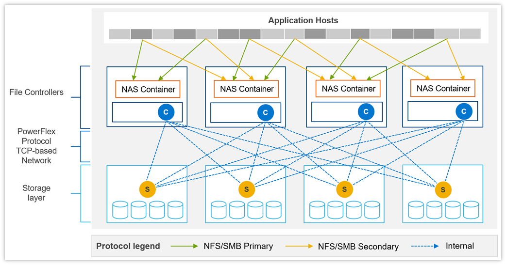
Example of data path communication between clients, NAS servers, and block storage backend.
File Controller Node Options
Component | Model | CPU | Cores | RAM(GB) | NIC (GbE) | Local Storage (GB) |
Small Node | PowerFlex R650S | Intel Xeon 2x5317 | 2x12 (24) | 128 | 4 x 25 | 480GB BOSS M.2 |
Medium Node | PowerFlex R650M | Intel Xeon 2x6346 | 2x16 (32) | 256 | 4 x 25 | 480GB BOSS M.2 |
Large Node | PowerFlex R650L | Intel Xeon 2x6348 | 2x28 (56) | 256 | 4 x 25 | 480GB BOSS M.2 |
Data Access Protocols
In addition to the file access protocols, listed above, PowerFlex supports two block protocols. The primary transport protocol is a proprietary TCP-based protocol that efficiently moves data between the Storage Data Servers (SDSs) and Storage Data Clients (SDCs), as well as among the contributing SDSs. The architecture includes native multipathing between the SDC and all SDSs that host volume data. The SDC translates this to a subset of the standard SCSI commands, for consumption by operating systems, hypervisors, and applications that can access raw block devices.
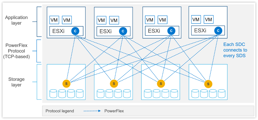 Example of SDC – SDS communication with SDC installed in ESXi.
PowerFlex 4.0 also introduced support for NVMe/TCP, allowing for the consumption of PowerFlex volumes without installing the proprietary kernel driver. Support for NVMe/TCP is facilitated by the Storage Data Target (SDT) service, which runs on nodes also running the SDS service. The SDT translates between the system’s native PowerFlex protocol and NVMe commands. It also functions as a discovery service for client initiators.
NVMe/TCP requires kernels that contain native support for the protocol. In VMware, this is ESXi 7.0 Update 3f or later. It is also available as a Tech Preview in supported Linux Distributions: RHEL 8.6 and later, SLES 15 SP3 and later, Ubuntu 22.04.
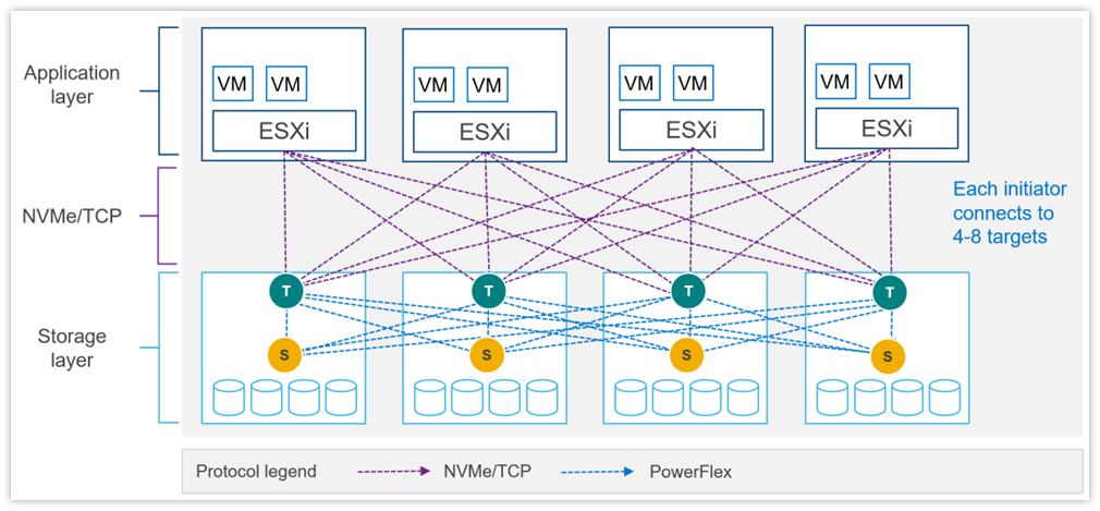 Example of NVMe/TCP communication with PowerFlex storage with ESXi.
NVMe/TCP Limits
PowerFlex Item | Product Limit |
Maximum volumes mapped to a single NVMe host (Linux) | 1024 |
Maximum volumes mapped to a single NVMe host (ESXi) | 32 (in ESXi 7.0) 256 (in ESXi 8.0) |
Maximum NVMe hosts connected to system | 1024 (included in total SDCs per system) |
Maximum SDTs per protection domain | 128 |
Minimum SDTs per protection domain | 2* |
Maximum SDTs per system | 512 |
Maximum paths in multipathing driver per volume | 8 (in ESXi 7.0u3) 32 (in ESXi 8.0u1) |
Maximum connections per host per protection domain | 16 |
Maximum NVMe host connections (I/O controllers) per SDT | 512 |
Maximum NVMe host connections (I/O controllers) per system | 65,519 |
Maximum I/O controller queue depth | 128† |
Maximum I/O controller queues | 32† |
Maximum volume-to-host mappings (SDC/NVMe) per system | 262,143 |
* Using minimum SDTs may block the ability to reach maximum NVMe hosts.
† Number of queues + queue depth is automatically negotiated on connection.
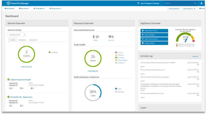
PowerFlex Manager (PFxM)
PowerFlex Manager is the M&O software layer that further enables ITOM automation and LCM capabilities for hardware and networking. Starting with PowerFlex 4.0, the unified PowerFlex Manager brings together three separate components used in previous releases – PowerFlex Manager, the core PowerFlex UI, and the PowerFlex gateway UI. The new PowerFlex Manager and UI runs as containerized services in a distributed Kubernetes platform
PowerFlex Manager offers standards-based open APIs and custom Ansible modules, making it simple to integrate with third party tools and custom workflows. Further, when paired with Dell CloudIQ, PowerFlex leverages an AI/ML-based approach to infrastructure monitoring and management, ensuring simplicity and consistency at scale.
PowerFlex Clustering, Scaling and Management | ||
Min Nodes Per Cluster (Two-layer Configuration) | 4 Storage Only nodes minimum (6 or more recommended) 1 to 3 Compute Only nodes (depending on host OS) | |
Min Nodes Per Cluster (HCI Configuration) | 4 HCI Nodes minimum (6 or more recommended) | |
Scaling Increments | 1 Node (HCI, Compute Only or Storage Only) † | |
PowerFlex Management Node Requirements‡ |
EmbeddedOS Jump Server Secure Connect Gateway PowerFlex Management VMs (3x) PowerFlex Enterprise Encryption and KeyStore (optional) |
16GB RAM, 4 vCPU, 500GB storage 4GB RAM, 2 vCPU, 16GB storage 32GB RAM, 16 vCPU, 650GB storage (each)
6GB RAM, 4 vCPU, 64GB storage |
(Supplied as virtual machine images) | ||
* In 2-layer environments where existing compute nodes are to be utilized or compute nodes are running an operating system not supported by PowerFlex Manager, the minimum requirement is for four storage nodes only.
† A single node is the minimum scaling required to expand an existing Storage Pool. Creation of a net new Storage Pool requires the addition of a minimum of 3 Storage or HCI Nodes.
‡ New PowerFlex appliance deployments include a single-node management controller (with an option for three-node for larger systems). New PowerFlex integrated rack deployments include a three-node or four-node management controller cluster. These PowerFlex Management Controller options are ESXi based.
PowerFlex Manager: Supported Switches
PowerFlex Manager Supported Switches | |
Management Switches* | Cisco Nexus 3172TQ, Cisco Nexus 31108TC-V, Cisco Nexus 92348GC-X, |
Access or Leaf Switches | Cisco Nexus 3132QX, Cisco Nexus 3164Q, Cisco Nexus 93180YC-EX, |
Aggregation or Spine Switches | Cisco Nexus 9236C, Cisco Nexus 9336C-FX2, Cisco Nexus 9364C-GX, Cisco Nexus 9364C-GX, Dell S5232F-ON |
* For PowerFlex appliance, the management switch can be “bring your own”.
‡ Appliance only
Power and Dimensions
| PowerFlex R660 | PowerFlex R760 | PowerFlex R6625 | PowerFlex R7625 | |
Fully redundant power supplies (100-240Vac) | 700 W Titanium 800 W Platinum 1100 W Titanium 1400 W Platinum 1800 W Titanium | 700 W Titanium 800 W Platinum 1400 W Platinum 1800 W Titanium 2400 W Platinum 2800 W Titanium | 700 W Titanium 800 W Platinum 1100 W Titanium 1400 W Platinum 1800 W Titanium | 700 W Titanium 800 W Platinum 1400 W Platinum 1800 W Titanium 2400 W Platinum 2800 W Titanium | |
Redundant cooling fans | 8 | 6 | 8 | 6 | |
Physical dimensions | H W D Wgt | 42.8 mm 434 mm 823 mm 21.2 kg | 86.8 mm 434 mm 772 mm 35.3 kg | 42.8 mm 434 mm 751 mm 21.2 kg | 86.8 mm 434 mm 700 mm 24.6 kg |
| PowerFlex R650 | PowerFlex R750 | PowerFlex R6525 | PowerFlex R7525 | |
Fully redundant power supplies (100-240Vac) | 800 W 1100 W 1400 W 1100 W (48-60Vdc) | 800 W 1100 W 1400 W 2400 W | 800 W 1100 W 1400 W 1100 W (48-60Vdc) | 1100 W 1400 W 2400 W | |
Redundant cooling fans | 8 | 6 | 8 | 6 | |
Physical dimensions | H W D Wgt | 42.8 mm 434 mm 751 mm 21.2 kg | 86.8 mm 434 mm 700 mm 35.3 kg | 42.8 mm 434 mm 751 mm 21.2 kg | 86.8 mm 434 mm 700 mm 24.6 kg |
| PowerFlex R640 | PowerFlex R740xd | PowerFlex R840 | |
Fully redundant power supplies (100-240Vac) | 750 W 1100 W 1600 W 1100 W (48Vdc) | 1100 W 1600 W 2000 W 2400 W | 1600 W 2000 W 2400 W | |
Redundant cooling fans | 8 | 6 | 6 | |
Physical dimensions | H W D Wgt | 42.8 mm 434 mm 734 mm 21.9 kg | 86.8 mm 434 mm 679 mm 28.1 kg | 86.8 mm 434 mm 679 mm 28.1 kg |
Environmental and Certificates
| PowerFlex R660 | PowerFlex R760 | PowerFlex R6625 | PowerFlex R7625 |
Ambient operating temperature (A2) | 10°C to 35°C | 10°C to 35°C | 10°C to 35°C | 10°C to 35°C |
Storage temperature range | -40°C to 65°C | -40°C to 65°C | -40°C to 65°C | -40°C to 65°C |
Operating relative humidity (non-condensing) | 8% to 80% | 8% to 80% | 8% to 80% | 8% to 80% |
Operating altitude with no deratings | 3048m | 3048m | 3048m | 3048m |
| PowerFlex R650 | PowerFlex R750 | PowerFlex R6525 | PowerFlex R7525 |
Ambient operating temperature (A2) | 10°C to 35°C | 10°C to 35°C | 10°C to 35°C | 10°C to 35°C |
Storage temperature range | -40°C to 65°C | -40°C to 65°C | -40°C to 65°C | -40°C to 65°C |
Operating relative humidity (non-condensing) | 8% to 80% | 8% to 80% | 8% to 80% | 8% to 80% |
Operating altitude with no deratings | 3048m | 3048m | 3048m | 3048m |
| PowerFlex R640 | PowerFlex R740xd | PowerFlex R840 |
Ambient operating temperature (A2) | 10°C to 35°C | 10°C to 35°C | 10°C to 35°C |
Storage temperature range | -40°C to 65°C | -40°C to 65°C | -40°C to 65°C |
Operating relative humidity (non-condensing) | 10% to 80% | 10% to 80% | 10% to 80% |
Operating altitude with no deratings | 3048m | 3048m | 3048m |
Statement of Compliance
Dell Information Technology Equipment is compliant with all currently applicable regulatory requirements for Electromagnetic Compatibility, Product Safety, and Environmental Regulations where placed on market.
Detailed regulatory information and verification of compliance is available at the Dell Regulatory Compliance website.
https://www.dell.com/REGULATORY_COMPLIANCE

PowerFlex Summer 2021 Updates Deliver on Execution, Compliance, and Confidence
Tue, 04 Jul 2023 09:48:51 -0000
|Read Time: 0 minutes
Execute Flawlessly – Comply Effortlessly – Be Confident
The summer 2021 release of Dell EMC PowerFlex Software-defined Infrastructure extends the PowerFlex family’s transformational superpowers, providing businesses with the agility to thrive in ever-changing economic and technological landscapes. The release of PowerFlex 3.6 and PowerFlex Manager 3.7 enables customers to supercharge their mission-critical workloads with enhanced automation and platform options. It safeguards workload execution with expanded continuity and compliance offerings. And businesses running PowerFlex can be confident in predictable outcomes at scale with new infrastructure insights, network resiliency enhancements, and integrated upgrade guidance.
Keep an eye on the important stuff
A highlight of this release is PowerFlex integration with Dell EMC CloudIQ, a cloud-based application that intelligently and proactively monitors the health of Dell EMC storage, data protection, HCI and other systems. Users can enjoy a single UI for multi-system, multi-site PowerFlex monitoring that includes system health, configuration/inventory, capacity usage, and performance. The PowerFlex system must be first connected to Dell EMC Secure Remote Services (SRS), and then CloudIQ is automatically enabled. Health scores are based on health check algorithms that use capacity, performance, configuration, components, and data protection criteria whose value is informed by PowerFlex alert data. Users can opt in to get health notifications via email or mobile phones, and the history of generated and cleared health issues is maintained for two years. After ingesting a couple of weeks of data, CloudIQ machine learning will begin looking for and noting IOPS and bandwidth anomalies. It also watches for and signals latency performance impacts.
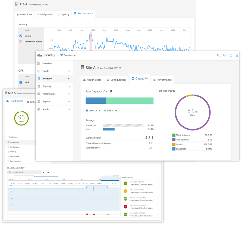
For information on adding your PowerFlex system(s) to CloudIQ see the Knowledge Base article. And to get a hands-on look at PowerFlex in CloudIQ, check out the online Simulator (log in with your support account) and see technical white papers and demo recordings on www.delltechnologies.com/cloudiq.
Be safe with your data out there
PowerFlex native asynchronous replication was introduced last year with version 3.5. Now, in PowerFlex 3.6, we have made it even more flexible and improved compliance targets. We cut the minimum RPO in half and now support RPOs as low as 15 seconds. We also added tooling to improve control over Replication Consistency Groups (RCGs) – sets of PowerFlex volumes being replicated together. RCGs can now be active or inactive, where inactive RCGs hold their configuration but use no additional system resources. The ability to terminate an RCG and leave it in an inactive state also improves the recovery process if a user runs out of journal capacity.
With this release, PowerFlex supports replication in VMware HCI environments. In this scenario, PowerFlex Manager 3.7 (and above) orchestrates resizing the Storage Virtual Machines (SVMs) and the addition of the Storage Data Replicators (SDRs) into the system. Because the orchestration is done by PowerFlex Manager, the option to replicate between PowerFlex HCI deployments running VMware is limited to appliance and rack deployments.
Systems running 3.5.x can be active replication peers with systems running 3.6, and the source and destination systems can be on different code versions long term. For further information about PowerFlex replication architecture, limitations and design considerations, see the Dell EMC PowerFlex: Introduction to Replication white paper.
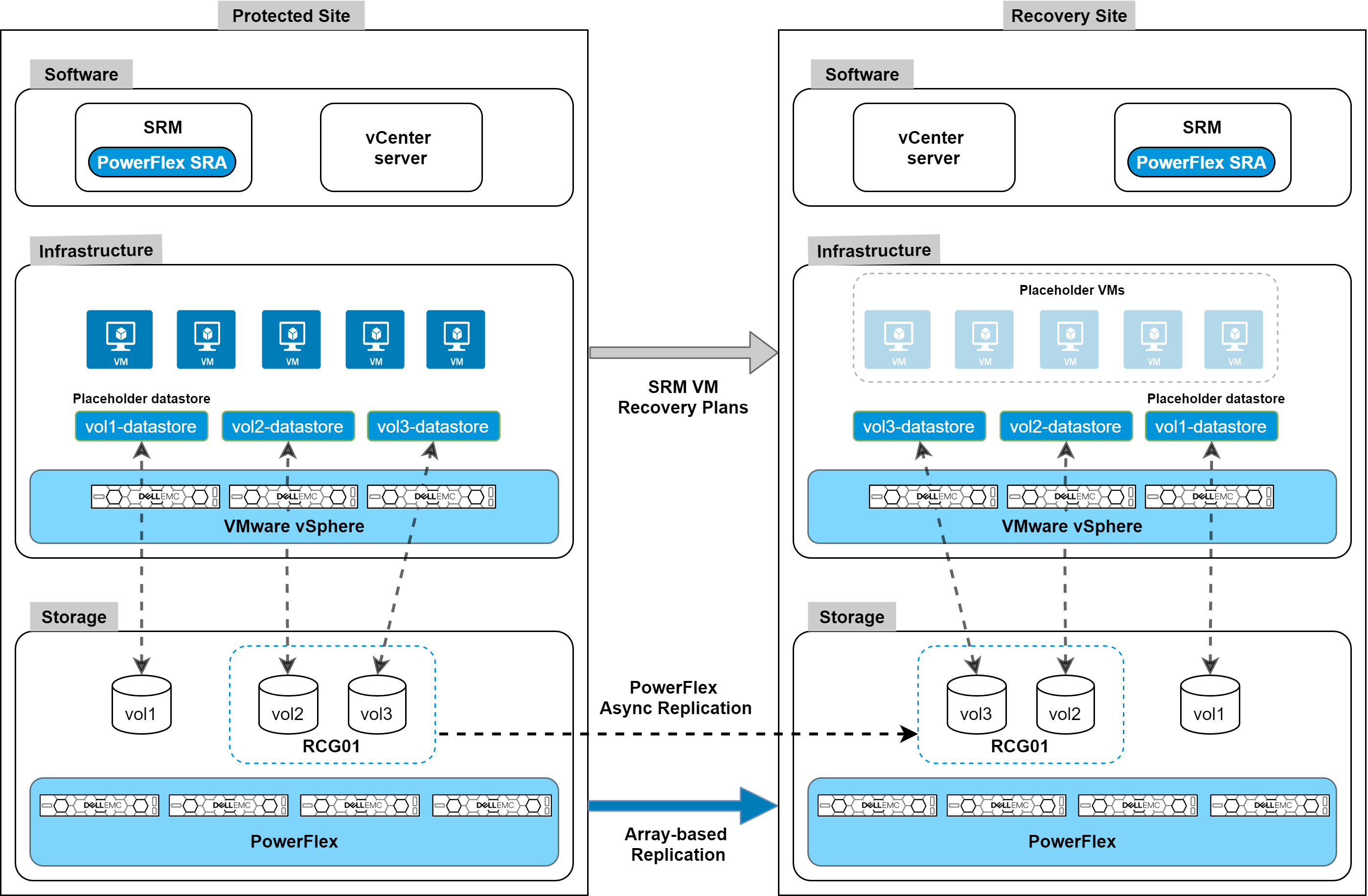
Along with these internal replication improvements, we are introducing integration with VMware Site Recovery Manager (SRM) – disaster recovery management and automation software for virtual machines and their workloads. The PowerFlex Storage Replication Adapter (SRA) enables PowerFlex as the native replication engine for protecting VMs on vSphere datastores. The PowerFlex SRA is compatible with SRM 8.2 or 8.3, the Photon OS-based SRM appliances. And while we are introducing this with the current releases, the SRA is compatible with PowerFlex systems running 3.5.1.x and above. Users can create recovery plans to failover VMs to another site, fail back to the original, or use PowerFlex’s non-disruptive replication failover testing to run failover tests in SRM.
The SRA and installation instructions are available for download from the VMware website. For detailed information about the SRA implementation and usage examples, see the whitepaper on Disaster Recovery for Virtualized Workloads Dell EMC PowerFlex using VMware Site Recovery Manager.
The following figure shows an architecture overview of PowerFlex SRA and VMware SRM:
PowerFlex native replication, and the integration with VMware Site Recovery Manager, provide robust, crash-consistent data protection for disaster recovery and business continuity. But we are also introducing integration with Dell EMC AppSync for application-consistent copy lifecycle management. For customers using the wide range of supported databases and filesystems, AppSync v4.3 adds support for PowerFlex, seamlessly bringing PowerFlex’s superpowers into AppSync’s simplified copy data management. AppSync has deep integrations with Oracle, Microsoft SQL Server, Microsoft Exchange, and SAP HANA, and it enables VM-consistent copies of data stores and individual VM recovery for VMware environments. But it can also support other enterprise applications – like EPIC Cache, DB2, MySQL, etc. – through file system copies.
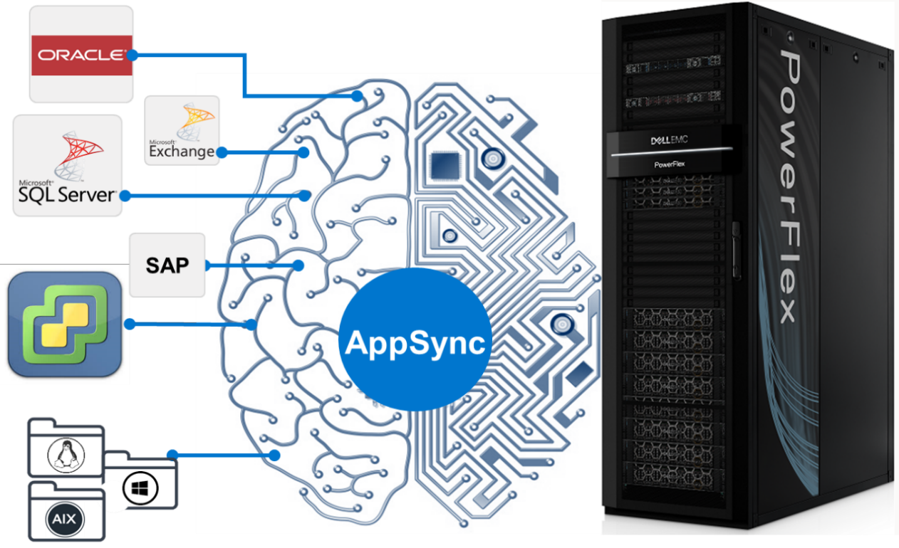
AppSync with PowerFlex integration will be available mid-July 2021. For information and examples, see the Dell EMC PowerFlex and AppSync integration video.
One more note on security. PowerFlex rack and appliance are now FIPS 140-2 compliant for data at rest and key management. Hardware based data at rest encryption is achieved using supported self-encrypting drives (SEDs), with the encryption engine running on the SEDs to deliver better performance and security. The SEDs based encryption claim is based on FIPS 140-2 Level 2 certification. Dell EMC CloudLink, the KMIP and FIPS 140-2 Level 1 (CloudLink Agent and CloudLink Server) compliant key manager, is used to manage SEDs encryption keys.
Automate (and containerize) all the things
PowerFlex software-defined infrastructure is eminently suited to cloud-native use cases and automatable workflows. There has been a lot of recent progress in PowerFlex’s support for these ecosystems. The Container Storage Interface (CSI) driver for PowerFlex continues to evolve, with support for accessing multiple PowerFlex clusters, ephemeral inline volumes, and importantly a containerized PowerFlex Storage Data Client (SDC) deployment and management. The containerized SDC allows CSI to inject the PowerFlex volume driver into the kernel of container-optimized operating systems that lack package managers. This provides PowerFlex CSI support for Red Hat CoreOS and Fedora Core OS. And it also enables integration of PowerFlex with RedHat OpenShift 4.6 and greater. The forthcoming CSI version 1.5 adds support for volume consistency groups and custom file system format options. Users can set specific disk format command parameters when provisioning a volume. Star and watch the GitHub Repository for the PowerFlex CSI Driver for updates.
In addition to this, Dell Technologies has been developing a set of Container Storage Modules (CSM) that complement the CSI drivers. PowerFlex is at the forefront of that effort, and there are several modules available for tech preview, with general availability coming later this year.
- Observability CSM: Provides exportable telemetry metrics for I/O performance & storage usage, for consumption in tools like Grafana and Prometheus. Bridges the observability gap between Kubernetes and PowerFlex storage admins.
- Authorization CSM: Provides a set of RBAC tools for PowerFlex and Kubernetes. This is an out-of-band tool proxying admin credentials and enabling the management of storage consumers and their limits (e.g., tenant segmentation, storage quota limits, isolation, auditing, etc.).
- Resiliency CSM: Provides stateful application fault protection & detection, resiliency for node failure and network disruptions. Reschedules failed pods on new resources and asks the CSI driver to un-map and re-map the persistent storage volumes to the online nodes.
Users can automate volume and snapshot lifecycle management with the PowerFlex Ansible Modules. They can also use the modules to gather facts about their PowerFlex systems and manage various storage pool and SDC details. The Ansible modules are available on GitHub and Ansible Galaxy. They work with Ansible 2.9 or later and require the PowerFlex Python SDK (which may also be used by itself to facilitate authentication to and interaction with a PowerFlex cluster). Again, watch the repositories for additional modules and expansions in the near future.
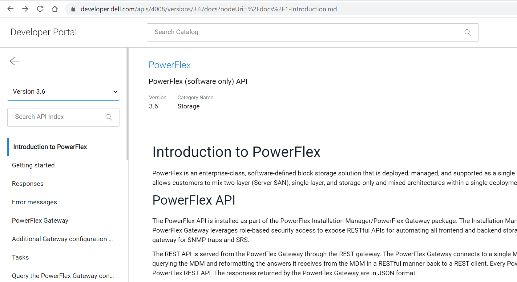
All these automation tools leverage and rely upon the PowerFlex REST API. And Dell Technologies has introduced a new Developer Portal, where the APIs for many products can be explored. The PowerFlex API, along with explanations and usage examples, can be found at https://developer.dell.com/apis/4008/versions/3.6/docs.
Always keep on improving
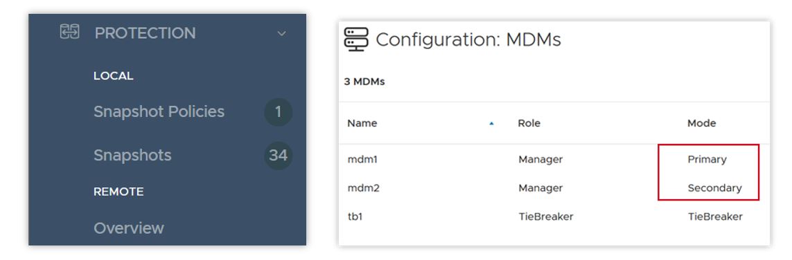
With every release, PowerFlex and PowerFlex Manager get faster, more secure, and more easily manageable. In PowerFlex 3.6 there are a number of UI enhancements, including simplification of menus, better capacity reporting around data reduction, a new dedicated area for snapshots and snapshot policy management, and – following on Dell Technologies’ drive towards more inclusive language – a change in the labels for the MDM cluster roles. “Master” and “Slave” roles are now “Primary” and “Secondary”.
PowerFlex 3.6 introduces support for Oracle Linux Virtualization (KVM based), which adds a supported hypervisor layer to the previous support for Oracle Enterprise Linux. This advances the numerous Oracle database deployments on PowerFlex, providing improved Oracle supportability while still offering the great cost-effectiveness PowerFlex offers for running Oracle. For detailed information on installing and configuring, please refer to the Oracle Linux KVM on PowerFlex white paper.
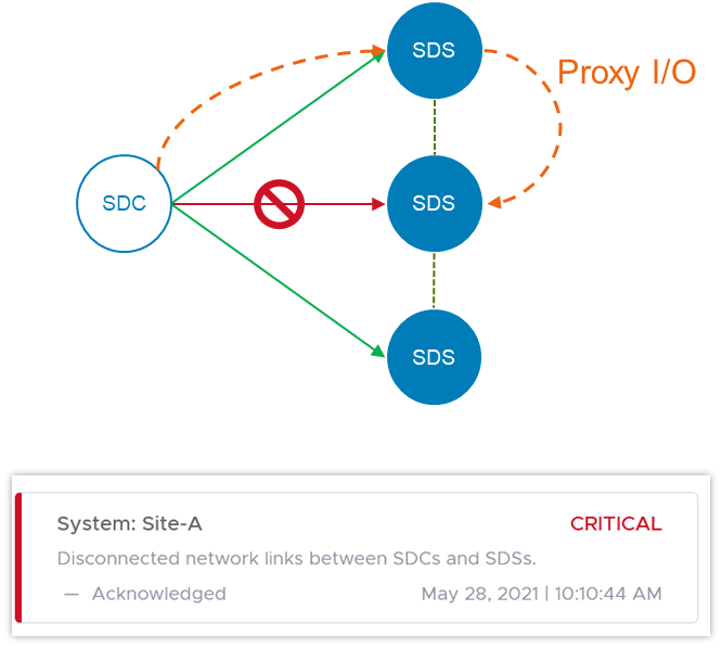
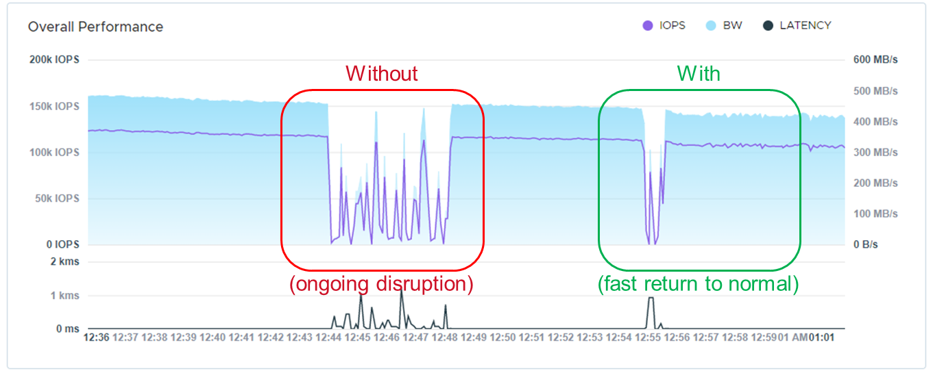
In the software-defined storage layer itself, version 3.6 doubles the number of Storage Data Clients (the consumers of PowerFlex volumes) per system to 2048. This doubles the number of hosts that can map volumes from PowerFlex storage pools. The software is also smarter when it comes to detecting and handling network error cases. In some disaggregated, or two-layer, systems where the SDCs live on a separate network than the storage cluster itself, a network path impairment between an SDC and a single Storage Data Server (SDS) node can cause I/O failures – even when there isn’t a general network failure in the cluster. In version 3.6 if such a disruption occurs, the SDC can use another SDS in the system to proxy the I/O to its original destination. Users are alerted until the problem is cleared, but I/O continues uninterrupted.
Because of the highly distributed architecture of PowerFlex, ports or sockets experiencing frequent disconnects (flapping), can cause overall system performance issues. 3.6 detects this and proactively disqualifies the path, preventing general disruption across the system.
In version 3.5, we introduced Protected Maintenance Mode (PMM), a super-safe way to put a node into maintenance while nevertheless avoiding a lengthy data-rehydration process at the end. Now, PMM makes use of the highly parallel many-to-many rebalancing algorithm, as a node goes into maintenance. Depending on the amount of data stored on the node, this can still be a long process, and other things can change in the system as it’s happening. PowerFlex 3.6 adds an auto-abort feature, in which the system continually scans for hardware or capacity issues that would prevent the node from completely entering PMM. If any flags are raised, the system will abort the process and notify the user. More information on maintenance modes, and the new PMM auto-abort feature, can be found in this whitepaper.
PowerFlex Manager 3.7 has gotten much more powerful as well. Foremost among the improvements is a new Compatibility Management feature. This new feature helps customers automatically identify the recommended upgrade paths for both the PowerFlex Manager appliance itself and the system RCM/IC upgrade. Prior to this release, whenever a customer or Dell Professional Services wished to do an upgrade, it took a lot of effort and time to manually investigate the documentation and compatibility matrixes to understand all of the upgrade rules – what are the allowed upgrade paths, which PowerFlex Manager version works with which RCM/IC versions, etc.
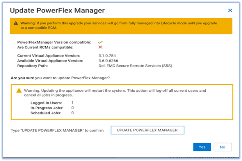
The new Compatibility Management tools eliminate the work and assist users by automatically identifying recommended upgrade paths. To determine which paths are valid and which are not, PowerFlex Manager uses information that is provided in a compatibility matrix file. The compatibility matrix file maps all the known valid and invalid paths for all previous releases of the software. It breaks the possible upgrade paths down as:
- Recommended: tested or implied as tested
- Supported: allowed, but not necessarily tested
- Not Allowed: unsupported update path
PowerFlex Manager 3.7 also introduces support for vSphere 7.0 U2. Upgrading to this version requires a manual vCenter upgrade. But then PowerFlex Manager will take over and manage the ESXi clusters. PowerFlex Manager 3.7 supports VMware ESXi 7.0 Update 2 installation, upgrade, and expansion operations for both hyperconverged and compute-only services. Users can deploy new services, add existing services running VMware ESXi 7.0 U2, or expand existing services. PowerFlex Manager also supports upgrades of VMware ESXi clusters in hyperconverged or compute-only services. You can upgrade VMware ESXi clusters from version 6.5, 6.7, or 7.0 to VMware ESXi 7.0 Update 2.
When you deploy a new ESXi 7.0U2 service, PowerFlex Manager automatically deploys two service volumes and maps these volumes to two heartbeat datastores on shared storage. PowerFlex Manager also deploys three vSphere Cluster Services (vCLS) VMs for the cluster.
PowerFlex Manager introduces several other enhancements in this release. It now supports 32k volumes per Service, aligned with PowerFlex core software volume scalability. It has enhanced security for SMB/NFS. A user-specific account is now required to gain access to the SMB share. PowerFlex Manager also updates the NFS share configuration when a user upgrades or restores the virtual appliance. PowerFlex Manager has disabled support for the SMBv1 protocol. PowerFlex Manager now uses SMBv2 or SMBv3 to enhance security.
It has also expanded its management capabilities over the PowerFlex Presentation Server and Gateway services. Prior to this release, PowerFlex Manager could deploy a Presentation Server (which hosts the WebUI) but not upgrade it. Now, PowerFlex Manager 3.7 can both discover existing instances and upgrade Presentation Servers. Similarly, it has gained the ability to upgrade the OS for the Gateway (which hosts the REST API). Prior to this release, PowerFlex Manager could only upgrade the Gateway RPM package without upgrading and patching the OS of the Gateway. Now PowerFlex Manager 3.7 can do both.
But it’s not all about software
This release adds support for a broader array of NVIDIA GPUs. Next-gen NVIDIA acceleration cards are now available for customers looking to run specialized, high-performance computing and analytics applications - Quadro RTX 6000, Quadro RTX 8000, A40, and A100. And we also introduce a small form factor GPU that can be used in the 1U R640-based PowerFlex Nodes – the NVIDIA A100. The past year demonstrated the importance supporting remote workers with virtual desktops, and PowerFlex supports GPU implementations on Citrix and VMware VDI.
We now support the Dell PowerSwitch S5296F-ON for the PowerFlex appliance. The S5295 has 96x 10/25G SFP28 ports and 8x 100G QSFP28 ports. It can support high node counts in a single cabinet, if the high oversubscription ratio is acceptable. We also introduce support for the Cisco Nexus 93180YC-FX, for use as either an access or an aggregation switch, and the Cisco 9364C-GX, for use as either a leaf or a spine switch, with 64x 100G ports.
Virtualized network infrastructure continues to grow in capability and deployment share. NSX-T™ is VMware's software-defined-network infrastructure that addresses cross-cloud needs for VM-centric network services and security. The PowerFlex appliance now joins the PowerFlex rack, in supporting NSX-T Ready configurations. “NSX-T Ready” means that the hardware configuration meets NSX-T requirements. The customer will provide NSX-T software and deploy with assistance from VMware or Dell Professional Services. The enabling components are:
- A 4-node PowerFlex management cluster, available to host the NSX-T controller VMs
- Appliance-specific NSX-T edge nodes (need 2 to 8 for running the NSX-T edge services)
- High-level NSX-T topologies and considerations available in the PowerFlex Appliance Network Planning Guide
- PowerFlex Manager will run the NSX-T edge nodes in Lifecyle Mode
As with the PowerFlex rack, appliance NSX-T edge nodes are “service appliances” that are dedicated to run network services, while the newly available HA appliance management nodes run the NSX-T management VMs. PowerFlex Manager can assist in deploying the edge nodes and will lifecycle the hardware aspects.
Wrap it up
Thanks for taking time to read about what’s new with Dell EMC PowerFlex software-defined infrastructure. We haven’t even been able to cover all the great new things being introduced this summer. Supercharge your mission-critical workloads flawlessly with enhanced automation, effortlessly enable business continuity and compliance, and confidently manage your data center operations at scale. To continue exploring, visit us on the Dell Technologies website for PowerFlex.

A Case for Repatriating High-value Workloads with PowerFlex Software-Defined Storage

Tue, 20 Oct 2020 12:16:04 -0000
|Read Time: 0 minutes
Kent Stevens, Product Management, PowerFlex
Brian Dean, Senior Principal Engineer, TME, PowerFlex
Michael Richtberg, Chief Strategy Architect, PowerFlex
We observe customers repatriating key applications from the Cloud, help you think about where to run your key applications, and explain how PowerFlex’s unique architecture meets the demands of these workloads in running and transforming your business
For critical software applications you depend upon to power core business and operational processes, moving to “The Cloud” might seem the easiest way to gain the agility to transform the surrounding business processes. Yet we see many of our customers making the move back home, back “On-Prem” for these performance-sensitive critical workloads – or resisting the urge to move to The Cloud in the first place. PowerFlex is proving to deliver agility and ease of operations for the IT infrastructure for high-value, large-scale workloads and data-center consolidation, along with a predictable cost profile – as a Cloud-like environment enabling you to reach your business objectives safely within your own data center or at co-lo facilities.
IDC recently found that 80% of their customers had repatriation activities, and 50% of public-cloud based applications were targeted to move to hosted-private cloud or on-premises locations within two years(1). IDC notes that the main drivers for repatriation are security, performance, cost, and control. Findings reported by 451 Research(2) show cost and performance as the top disadvantages when comparing on-premises storage to cloud storage services. We’ve further observed that core business-critical applications are a significant part of these migration activities.
If you’ve heard the term “data gravity,” which relates to the difficulty in moving data to and from the cloud and that may only be part of the problem. “Application” gravity is likely a bigger problem for performance sensitive workloads that struggle to achieve the required business results because of scale and performance limitations of cloud storage services.
Transformation is the savior of your business – but a problem for your key business applications
Business transformation impacts the data-processing infrastructure in important ways: Applications that were stable and seldom touched are now the subject of massive changes on an ongoing basis. Revamped and intelligent business processes require new pieces of data, increasing the storage requirements and those smarts (the newly automated or augmented decision-making) require constant tuning and adjustments. This is not what you want for applications that power your most important business workflows that generate your profitability. You need maximum control and full purview over this environment to avoid unexpected disruptions. It’s a well-known dilemma that you must change the tires while the car is driving down the road – and today’s transformation projects can take this to the extreme.
The infrastructure used to host such high-profile applications – computing, storage and networking – must be operated at scale yet still be ready to grow and evolve. It must be resilient, remain available when hardware fails, and be able to transform without interruption to the business.
Does the public cloud deliver the results you expected?
Do your applications require certain minimum amounts of throughput? Are there latency thresholds you consider critical? Do you require large data capacities and the ability to scale as demands grow? Do require certain levels of availability? You may assume all these requirements come with a “storage” product offered by the public cloud platforms, but most fall short of meeting these needs. Some require over-provisioning to get better performance. High availability options may be lacking. The highest performing options have capacity scale limitations and can be prohibitively expensive. If you assume what you’ve been using on-prem comes from a hyperscaler, you may be quite surprised that there are substantial gaps that require expensive application rearchitecting to be “cloud native” which may become budget busters. These public cloud attributes can lead to “application gravity” gaps.
While the agility of it is tempting, the unexpected costliness of moving everything to the public cloud has turned back more than one company. When evaluating the economics and business justification for Cloud solutions, many costs associated with full-scale operations, spikes in demand or extended services can be hard to estimate, and can turn out to be large and unpredictable.
The full price of cloud adoption must account for the required levels of resiliency, management infrastructure, storage and analytics for operational data, security solutions, and scaling up the resources to realistic production levels. Recognizing all the necessary services and scale may undermine what might have initially appeared to be a solid cost justification. Once the budget is established, active effort and attention must be devoted to monitoring and oversight. Adapting to unexpected operational events, such as bursting or autoscaling for temporary spikes in workload or traffic, can bring unforeseen leaps in the monthly bill. Such situations can be especially hard to predict and plan for – and very difficult to control.
You want the speed, convenience and elasticity of running in the cloud - but how do you ensure that agility while staying within the necessary bounds of cost and oversight? Truly transformative infrastructure allows businesses to consolidate compute and storage for disparate workloads onto a single unified infrastructure to simplify their environment, increase agility, improve resiliency and lower operational costs. And your potential payoff is big with far easier scaling, more efficient hardware utilization, and less time spent figuring out how to get things right or tracking down issues that complicate disparate system architectures.
Software-Defined is the Future
IDC Predicts that by 2024, software-defined infrastructure solutions will account for 30% of storage solutions(3). At the heart of the PowerFlex family, and the enabler of its flexibility, scale and performance is PowerFlex software-defined storage. The ease and reliability of deployment and operation is provided by PowerFlex Manager, an IT operations and lifecycle management tool for full visibility and control over the PowerFlex infrastructure solutions.
PowerFlex’s unmatched combination of flexibility, elasticity, and simplicity with predictable high performance - at any scale - makes it ideally suited to be the common infrastructure for any company. Utilizing software defined storage (SDS) and hosting multiple heterogeneous computing environments, PowerFlex enables growth, consolidation, and change with cloud-like elasticity – without barriers that could impede your business.
The resulting unique architecture of the PowerFlex family easily meets the large-scale, always-on requirements of our customers’ core enterprise applications. The power and resiliency of the PowerFlex infrastructure platforms handle everything from high-performance enterprise databases, to web-scale transaction processing, to demanding business solutions in various industries including healthcare, utilities and energy. And this includes the new big-data and analytical workloads that are quickly augmenting the core applications as the business processes are being transformed.
PowerFlex: A Unique Platform for Operating and Transforming Critical Applications
 PowerFlex provides the flexibility to utilize your choice of tools and solutions to drive your transformation and consolidation, while controlling the costs of the relentless expansion in data processing. PowerFlex provides the modularity to adapt and grow efficiently while providing the manageability to simplify your operations and reduce costs. It provides the scalable infrastructure on-premises to allow you focus on your business operations. PowerFlex on-demand options by the end of 2020 enable an elastic OPEX consumption model as well.
As your business needs change, PowerFlex provides a non-disruptive path of adaptability. As you need more compute, storage or application workloads, PowerFlex modularly expands without complex data migration services. As your application infrastructure needs change from virtualization to containers and bare metal, PowerFlex can mix and match these in any combination necessary without needing physical changes or cluster segmentation. PowerFlex provides future-proof capabilities that keep up with your demands with six nines of availability and linear scalability.
With the dynamic new pace of growth and change, PowerFlex can ensure you stay in charge while enabling the agility to adapt efficiently. PowerFlex enables you to leverage the advantages of oversight and cost-effectiveness of the on-premises environment with the ability to meet transformation head-on.
For more information, see PowerFlex on Dell EMC.com, or reach out to Contact Us.
footnotes:
1 IDC Cloud Repatriation Accelerates in a Multi-Cloud World, July 2018
2 451 Research, 2020 Voice of the Enterprise
3 IDC FutureScape: Worldwide Enterprise Infrastructure 2020 Predictions, October 2019