
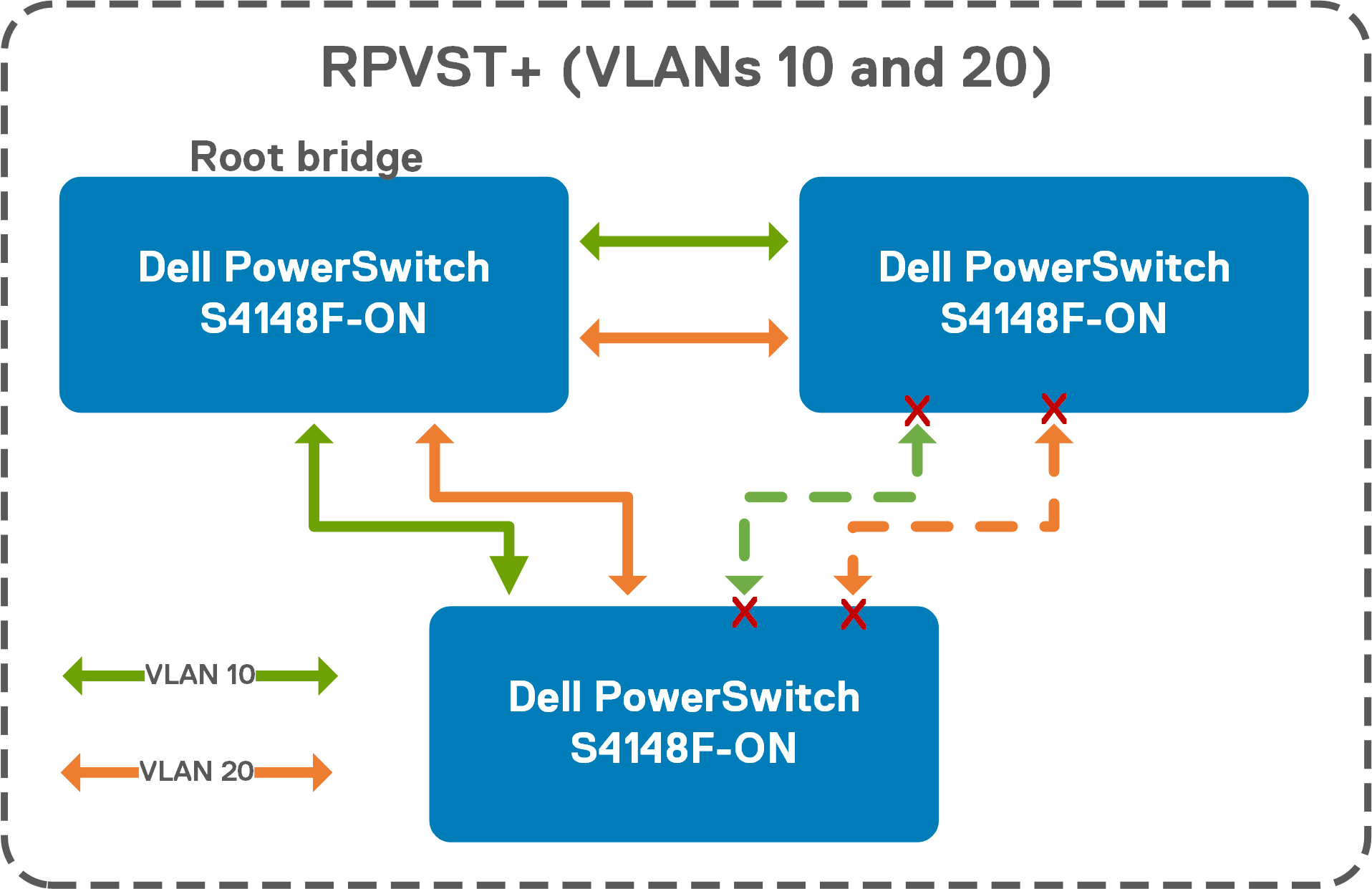
The Spanning Tree Protocol (STP) in Ethernet networks is used to build a loop-free logical topology to prevent bridge loops which result in broadcast storms. Virtually all topologies should implement spanning tree. When a loop is detected, spanning tree automatically shuts down an interface or port channel, as shown in Figure 12. There are multiple spanning tree protocols supported in SmartFabric OS10 including Rapid Spanning Tree Protocol (RSTP), Rapid Per-VLAN Spanning Tree+ (RPVST+), and Multiple Spanning Tree (MST). Each of these protocols is covered in detail in the SmartFabric OS10 User Guide.
Configuring the commonly used RPVST+ protocol is demonstrated in the example below. RPVST+ is enabled by default in SmartFabric OS10. Port-channels or physical interfaces must be a member of a VLAN to participate in RPVST+. A spanning tree instance is created for a VLAN upon adding the first member port to the VLAN.
There are several global and port level configuration commands for spanning tree. Global commands are used to enable/disable spanning tree on the entire switch, whereas port level commands are used to limit or supplement spanning tree features on individual ports.
From global configuration mode, the example commands below set the spanning tree mode on each switch to RPVST+ (default), and then sets the priorities for each VLAN on each switch. This bridge priority helps determine which switch on the network is more likely to become the root bridge for a VLAN when loops are detected on that particular VLAN. There are 16 bridge priorities ranging from 0 to 61440, in increments of 4096. Lower priority numbers are more likely to become the root bridge. Switches that you do not care about becoming the root can usually be left at the default priority of 32768, or raised as high as the highest setting of 61440.
| Configure RPVST+ on desired root bridges | Configure RPVST+ on other switch VLANs |
| |
The show spanning-tree active and show spanning-tree brief commands are used to see the spanning tree configuration and status, including which ports are currently blocking and which ports are forwarding for each VLAN on the switch.
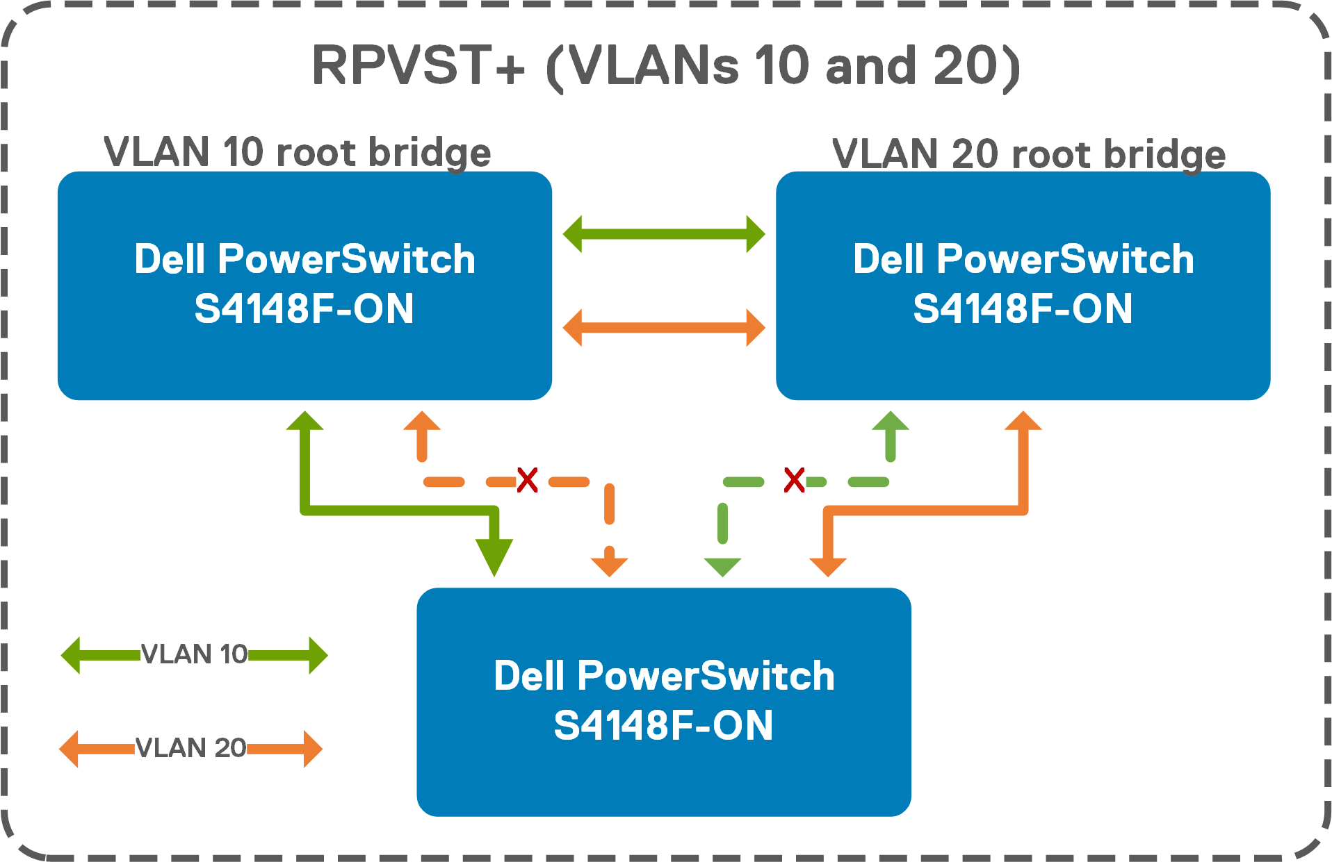
Notice that one of the trunks in the RPVST+ blocking interfaces on multiple VLANs and switches figure is not being used to pass traffic for either VLAN since a single switch on the network was assigned the root bridge role. For RPVST+ demonstration purposes, now give VLAN 10 the lower priority on one switch, and VLAN 20 the lower priority on another switch. Two root bridges are now created, one for each VLAN, as shown in the RPVST+ with multiple root bridges figure. While designing or modifying a network, the topologies need to be carefully designed, with all possible root bridge assignments considered and properly configured.
The show spanning-tree active and show spanning-tree brief commands are used to see the spanning tree configuration and status, including which ports are currently blocking and which ports are forwarding for each VLAN on the switch.