
SAP HANA I/O patterns
SAP HANA I/O patterns
-
The SAP HANA persistent devices use multiple I/O patterns:
Data volume
Access to the data volume is primarily random, with blocks ranging from 4 KB to 64 MB. The data is written asynchronously with parallel IOPS to the datafile system. During normal operations, most of the I/O operations per second to the datafile system are writes; data is read from the file system only during database restarts, SAP HANA backups, host autofailover, or a column store table load or reload operation.
Log volume
Access to the log volume is primarily sequential, with blocks ranging from 4 KB to 1 MB. SAP HANA keeps a 1 MB buffer in memory for the redo log. When the buffer is full, it is synchronously written to the log volume. When a database transaction is committed before the log buffer is full, a smaller block is written to the file system. Because data is written synchronously to the log volume, a low latency for the I/O to the storage device is important, especially for the smaller 4 KB and 16 KB block sizes.
During normal database operations, most of the I/Os to the log volume are writes; data is read from the log volume only during database restart, HA failover, log backup, or database recovery.
SAP HANA shared file systems
In an SAP HANA scale-out implementation, install the SAP HANA database binaries on a shared file system that is exposed to all hosts of a system under the /hana/shared mount point. If a host must write a memory dump, which can read up to 90 percent of the RAM size, the memory dump is stored in this file system. Depending on your infrastructure and requirements, you can use:
- An NFS server-based shared file system.
- A NAS system such as Dell PowerStore Unified File, Unity XT File, VMAX3 eNAS, or PowerMax eNAS, to provide an NFS share for the SAP HANA shared file system.
- PowerStore, PowerMax, or Unity XT block storage to create a shared file system using a cluster file system such as General Parallel File System (GPFS) or Oracle Cluster File System 2 (OCFS2) on top of the block LUNs. SUSE provides OCFS2 capabilities with the HA package. The HA package is also part of the SUSE Linux Enterprise Server (SLES) for SAP Applications distribution.
Note: A SUSE license is required for HA.
SAN connectivity for metro node
This section describes hardware connectivity best practices for connecting metro node systems to the SAN. These best practices are based on dual fabric SAN, as shown in the following figure:
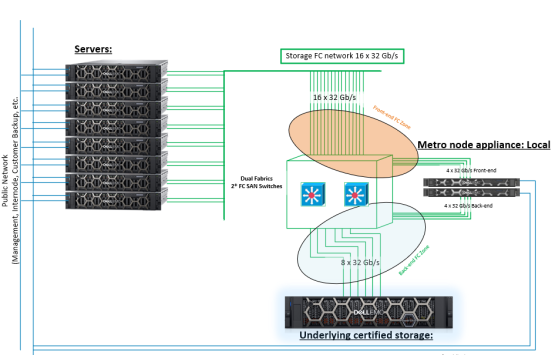
Figure 3. Architecture overview example of metro node in a local configuration
A single metro node cluster consists of two directors, A and B, as shown in the following figure:
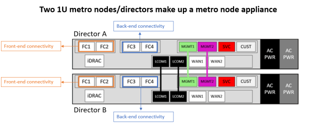
Figure 4. Metro node appliance
The cabling requirements for metro node and port assignments are:
- FC1/FC2 on front-end SAN fabrics
- FC3/FC4 on back-end SAN fabrics
- LCOM1, LCOM2, MGMT1, and MGMT2 ports, which have direct interconnections
- SVC (service) port, which is free for temporary connection of a service laptop
- CUST ports connected to the management network
- WAN1/WAN2 ports on intercluster WAN IP networks
Metro node director
A metro node director is the component that processes the I/O requests from the hosts in a metro node environment Metro, interacting with the back-end storage arrays to service the I/Os. A director has two I/O modules for servicing I/Os from the arrays: one for the connectivity with the storage arrays on the back-end, and one for connecting to the hosts on the front-end. The management module in the director is used for management connectivity to the directors and for intracluster communication. The local communication module is dedicated to intracluster communication.
The front-end ports on all directors can provide access to any virtual volume in the cluster. Include multiple front-end ports in each storage view to protect against port failures. When a director port fails, the host multipathing software seamlessly fails over to another path through a different port. The front-end ports log in to the fabrics and present themselves as targets for zoning to the host initiators, and the back-end ports log in to the fabrics as initiators to be used for zoning to the storage array targets. Each director connects to both SAN fabrics with both front-end and back-end ports.
Metro node FC I/O modules are 32 Gb-capable, supporting front-end and back-end connectivity.
Each metro node appliance uses the FC1 and FC2 front-end ports of each director and the FC3 and FC4 back-end ports for fabrics A and B, as shown in Figure 4. For the FC zoning, each initiator from metro node back-end ports is zoned to multiple targets from PowerStore FC ports. The following table shows an example of back-end zoning with dual fabrics:
Table 1. Metro node back-end zoning example
Metro node back-end port
PowerStore port
Director A – FC3
5000T-node A-FC0
Director A – FC3
5000T-node B-FC0
Director A – FC4
5000T-node A-FC2
Director A – FC4
5000T-node B-FC2
Director B – FC3
5000T-node A-FC1
Director B – FC3
5000T-node B-FC1
Director B – FC4
5000T-node A-FC3
Director B – FC4
5000T-node B-FC3
On the metro node appliance front-end, each HBA is connected to a dual fabric and zoned to multiple targets of each metro node director. This zoning connects four paths from the host to the metro node appliance. The following table shows an example of front-end zoning:
Table 2. Metro node front-end zoning with dual fabrics
Metro node front-end port
HBA
Director A – FC1
HBA1 of each server
Director B – FC1
HBA1 of each server
Director A – FC2
HBA2 of each server
Director B – FC2
HBA2 of each server
Front-end connectivity
Metro node virtual volumes are seen by the hosts as the same metro node volumes, regardless of what physical array sits behind the metro node. Although the back-end array is Asymmetric Logical Unit Access (ALUA), metro node is a true active/active array. For zoning purposes, metro node is the endpoint and metro node front-end ports present WWPN targets to which to zone for the host connectivity.
Dell Technologies recommends following these best practices when connecting SAP HANA nodes to a metro node cluster:
- Dual fabric design (preferred).
- The front-end I/O modules on each metro node director have a minimum of two physical connections, one to each fabric (required).
- Each SAP HANA host bus adapter (HBA) port has at least one path to an A director and one path to a B director on each fabric for a total of four logical paths (required for non-disruptive upgrades (NDU).
- Multipathing or path failover software at the host for access across the dual fabrics (required).
- Each host has fabric zoning that provides redundant access to each LUN from a minimum of one A and B director from each fabric.
- Four paths from the host to metro node (required for NDU). Use the skip option for the NDU start command for host connectivity with fewer than four paths and is not considered a best practice (required).
- Avoid an incorrect FC port speed between the fabric and the metro node cluster. Use the highest possible bandwidth to match the metro node maximum port speed, and use dedicated port speeds―that is, do not use oversubscribed ports on SAN switches.
Back-end connectivity
Follow these best practices when connecting metro node to a storage array:
- Each director has redundant physical connections to the back-end storage across dual fabrics. Each director has redundant paths to every back-end storage array across both fabrics (required).
- The back-end I/O modules on each metro node director have a minimum of two physical connections, one to each fabric (required).
- Each director has four active paths to a given LUN. Each director will load-balance across the four active paths to the storage volume.
- All metro nodes that are used by the SAP HANA hosts are connected to the storage array.
Note: back-end port-to-array direct connect is not supported based on the Initiator/Target/LUN (ITL) path count requirements.
- Each metro node director has eight logical paths to the storage device or LUN, with four going to the active controller and four to the passive controller (required).
- Each metro node back-end port has at least two paths to each controller at the array (required for NDU).
Note: For more information about metro node front-end and back-end array connectivity, see the Dell EMC VPLEX SAN Connectivity Implementation Planning and Best Practices Technical Notes.
Metro node scalability for SAP HANA
Metro node is an additional layer between the SAP HANA hosts and the certified storage arrays, providing new functionality while also affecting throughput and latency.
This section describes metro node configuration with LUNs that are exported 1:1 from the storage array through the metro node to the hosts. Adding local mirrors, splitting volumes across multiple arrays, and using other mobility, availability, and collaboration features might have an additional impact on performance.
Note: In this configuration, the SAP HANA KPIs were fulfilled without DR support. For SAP HANA TDI enterprise storage certification, the performance KPIs do not take DR support into consideration.
The maximum number of hosts that can be connected depends on the capabilities of the metro node cluster and the underlying storage array. A metro node cluster can serve about 80 percent of the maximum number of hosts of the underlying storage arrays. For example, if the storage array is certified for up to 10 hosts, the metro node can cater to eight SAP HANA hosts. Further, the metro node itself has a maximum number of hosts that can be connected in SAP HANA production systems.
Metro node scalability tests
Using the SAP HCMT tool for HANA-HWC-ES 1.1 certification, we tested a metro node single cluster engine to derive scalability guidelines for estimating the initial number of SAP HANA production hosts that can be connected to the metro node appliance. Based on the results of our testing, the maximum number of SAP HANA workers that can be connected to a metro node is 30. The number of SAP HANA hosts can be higher or lower than that number, depending on the workload. Use the HCMT tool with the HANA-HWC-ES 1.1 scenario to validate the SAP HANA performance and determine the maximum number of SAP HANA hosts on a given metro node configuration.
Note: Although test results might vary in different environments, Dell Technologies recommends not exceeding the number of hosts that are specified in this guide.
To determine the maximum number of SAP HANA hosts that can be supported, we used the min() function to compare two values, the maximum number of SAP HANA hosts that the metro node supports and 80 percent of the maximum number of SAP HANA hosts that the certified physical storage array supports, as follows:
max hosts = min(<max metro node hosts>, <max storage array(s) hosts> * 0.8)
The smaller of the two values is the number of SAP HANA worker nodes that can be supported.
Example 1
This example demonstrates how to physically connect a PowerStore 5000T system to SAP HANA servers using a metro node Local cluster configuration. A single PowerStore 5000T system can support up to 16 SAP HANA nodes. For more information, see the Validated Storage Configuration Guidelines for SAP HANA TDI deployments on Dell EMC PowerStore Systems design guide.
Using metro node with this storage model gives the following calculation:
max hosts = min(30, 16*0.8) = 12.8 SAP HANA hosts
Note: An I/O module with four front-end ports per PowerStore node (eight front-end ports per appliance) is required for 13 SAP HANA nodes.
Example 2
This example shows how to calculate the maximum number of SAP HANA hosts for multiple arrays that are connected to a metro node appliance. It uses a PowerMax 2000 two-brick system (supporting up to 40 SAP HANA hosts) and a single PowerStore 5000T system (supporting up to 16 SAP HANA hosts). Calculate the maximum number of supported hosts as follows:
max hosts = min[30, (40+16)*0.8 = 44.8] = 30