
Blogs
Short articles related to PowerProtect Data Manager.

PowerProtect Data Manager – Kubernetes data protection for CSI volumes without CSI snapshots
Fri, 12 Jan 2024 18:58:56 -0000
|Read Time: 0 minutes
In this blog, we’re continuing the tradition of great (and humble 😊) PowerProtect Data Manager and k8s blogs. Other than that, in this blog, I want to introduce you to a groundbreaking new capability we’ve added in the recent PowerProtect Data Manager 19.15 release which is the ability to protect CSI (Container Storage Interface) volumes without CSI snapshots.
This new ability is advantageous mostly in cases where the CSI does not support snapshots. In other words, we are enabling the protection of CSI volumes which was otherwise difficult to protect.
So, let’s take a closer look at this new capability.
Protection of non-snapshot CSI PVCs – what does it do ?
This feature enables protection for CSI PVCs (Persistent Volumes Claims) without the use of CSI snapshots. This introduces a way to backup volumes which were provisioned by a CSI driver without support for snapshots. Refer to this list of available CSI drivers and their snapshot support status.
What are the challenges this capability comes to solve ?
The main use case this newly added capability comes to solve is backup of CSI network file shares (or NFS) that have no snapshotting capability with their CSI driver. vSAN File Services (vSAN-FS) is a prime example of that. Now PowerProtect Data Manager can protect RWX PVCs (volumes which were provisioned with the Read Write Many volume access mode) which are quite popular for many use cases and also prevalent for NFS CSI drivers.
Another challenge worth talking about is CSI snapshots, there are cases where even if the CSI driver supports snapshots, there are certain inefficiencies that are mostly related to volume cloning and are storage platform dependent. Therefore, another advantage of PPDM’s ability to backup CSI volumes without the use of CSI snapshots is that it is not tied to a specific storage platform.
How does this feature work ?
This backup of non-snapshot CSI PVCs feature is an opt-in feature meaning that the user can choose which storage class this feature would apply for; but by default, PPDM would opt to use CSI snapshots as the primary data path.
For protection of workloads which use PVCs provisioned on storage classes to be used for non-snapshot backups, the data mover pod (AKA cProxy pod) is updated with topology specifications so that it would run on the same k8s worker node as the original pod(s).
The cProxy pod mounts the PVCs in read-only mode without detaching or impacting the user application volume. This enables the feature to support the Read Write Once (RWO) volume access mode but other \access modes such as Read Write Many (RWX) and Read Only Many (ROX) are supported as well for protection of CSI PVCs without CSI snapshot.
OK, how do I configure backup of non-snapshot PVCs ?
The first step is to edit the k8s asset source and under advanced options, add the controller configuration key/value pair:
Configuration Key: k8s.ppdm.csi.nonsnapshot.storageclasses
Supported Value: Comma-separated list of non-snapshot CSI storage classes
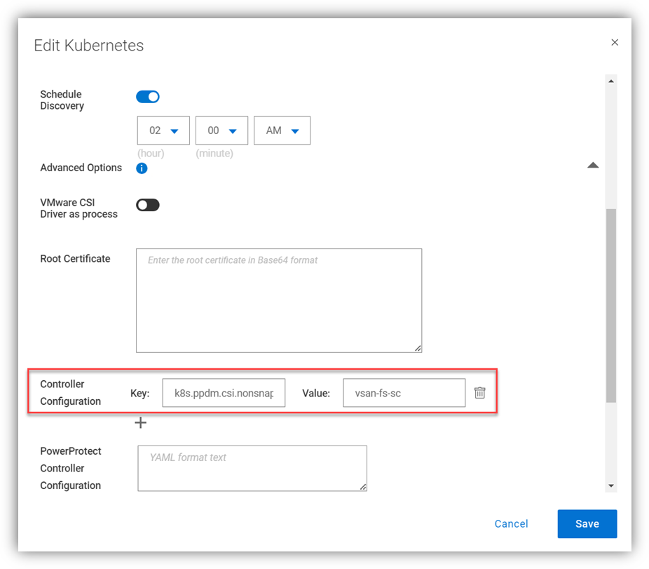 A
A
Naturally, this can be configured when the k8s cluster is added as an asset source for the first time.
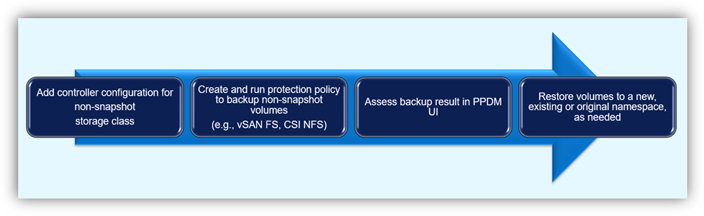
Afterwards, we just need to protect the workload by creating a protection policy and running a backup. I won’t spend much time talking about the protection process as it’s pretty straightforward, but I will include a nice little diagram to illustrate the flow here:
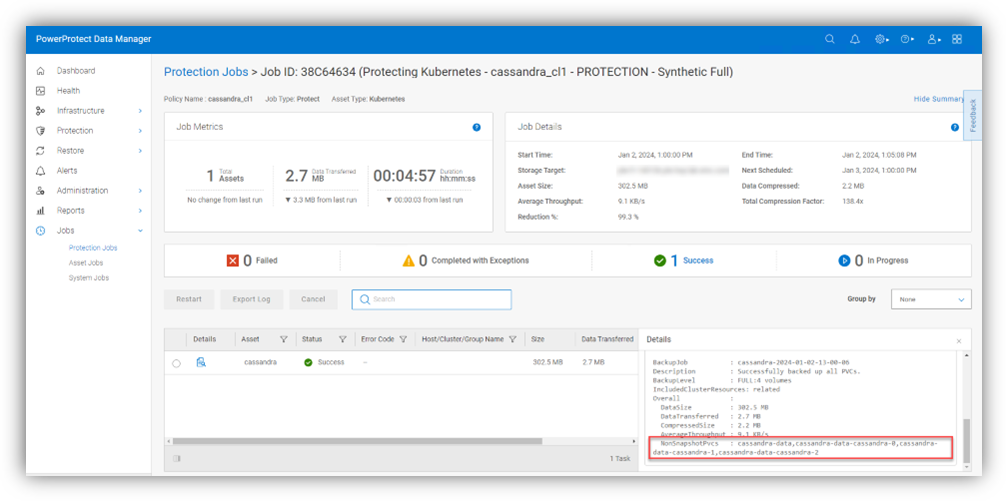
The protection job details include list of PVCs which were backed up without CSI snapshots under the NonSnapshotPvcs field.
Caveats and recommendations
So, I thought it would be helpful to talk about few important caveats and recommendations.
- The ability to protect CSI PVCs without CSI snapshots performs a backup of a live file system which means that data may not be captured at the same exact point-in-time as the CSI snapshot approach.
- As of PPDM 19.15, every backup of non-snapshot CSI PVCs is a full backup of the live volume. Open files would be skipped, detected, and logged by the controller so that they will be included in the next backup. The number of skipped files is shown in the PPDM UI under Jobs -> Protection Jobs for job type protect. The file paths of the skipped files appear in the controller logs (the powerprotect-controller pod running on the powerprotect namespace), which are pulled into the /logs/external-components/k8s directory on the PPDM appliance.
- The cProxy (data mover) pod is running in the user namespace as part of the backup flow so there is a need to make sure that the PPDM service account can create and delete secrets in that namespace. The PPDM RBAC YAML files can help with creating the required service account for PPDM discovery and operations. The rbac.tar.gz can be retrieved in one of the following ways:
- You can download the archive from the PowerProtect Data Manager UI by navigating to this location: Settings > Downloads > Kubernetes > RBAC
- Retrieve the rbac.tar.gz file from the PPDM appliance at the following location: /usr/local/brs/lib/cndm/misc/rbac.tar.gz
Note that the there is no requirement to provide root access to the host file system.
- vSphere CSI considerations – The vSphere CSI decides whether to provision PVCs from block storage or vSAN-FS (vSAN File Services) based on volume access mode therefore the recommendation is to separate storage classes for block and vSAN-FS. PPDM would automatically use non-snapshot on configured storage classes for PVCs with access mode of Read Only Many (ROX) and Read Write Many (RWX) as these result in PVC being provisioned on vSAN-FS.
Contrarily, PPDM would automatically backup PVCs that are provisioned using Read Write Once (RWO) with the optimized data path for VMware First Class Disks (or FCDs). So, even if there are PVCs provisioned on vSAN-FS and FCD on the same storage class, PPDM has the intelligence to trigger the most suitable data path granted that storage class is configured for non-snapshots as per the configuration we talked about earlier.
Resources
Always remember - documentation is your friend! The PowerProtect Data Manager Kubernetes User Guide has some useful information for any PPDM with K8s deployment. Furthermore, make sure to check out the PowerProtect Data Manager Compatibility Matrix.
Thanks for reading, and feel free to reach out with any questions or comments.
Idan

PowerProtect Data Manager Automation – Lifecycle Management
Mon, 20 Nov 2023 15:42:26 -0000
|Read Time: 0 minutes
In this installment of the PowerProtect Data Manager (PPDM) automation series of blogs, we will focus on a new solution that automates PowerProtect Data Manager life cycle management.
For PPDM automation, we have auto-policy creation and ad-hoc VM backup solutions, use-case driven tasks, complete PPDM deployment automation, and so on - all available in the official PowerProtect Data Manager GitHub repository. And now, I am proud to present to you the PPDM life cycle automation solution.
So, let’s take a closer look at the solution.
What does the solution do?
The PowerProtect Data Manager automated life cycle management automates PPDM upgrades with a wide variety of options:
- Upgrade with an upload package
- Performs pre-upgrade checks
- Continuously monitors pre-upgrade checks and upgrade processes
- Includes an option to skip the upload of the upgrade package and use the existing upgrade package
- Can perform only the pre-checks, without performing the actual upgrade
- Supports monitoring only phase where a current upgrade can be monitored
- Allows to skip PPDM VM snapshot. In any case, that snapshot will not be taken if a hosting vCenter is not configured
What is the solution?
It is a Python-based script that operates with the PPDM REST API.
Here is the list of prerequisites:
- Python 3.x (The script supports every platform Python is supported on)
- Python requests module, which can be installed using pip with the command: “pip install requests” or “python -m pip install requests”
- PowerProtect Data Manager 19.13 and later
- Connectivity from the host running the script to PPDM, specifically on tcp ports 8443 and 14443
How do I use the script?
The script accepts the following parameters:
- The PPDM host is represented by the mandatory parameter server and username (defaults to user admin) and a mandatory password parameter
- The parameter file for a full path to the upgrade package or, alternatively the skipupload parameter with the release parameter to determine the PPDM version to be applied
- The parameter onlyprecheck allows to perform precheck and exit without performing the actual upgrade
- Specify skipsnapshot to prevent VM snapshot from being taken on the PPDM VM
- The onlymonitor parameter performs monitoring of active upgrades
Here is the full script syntax:
# python ppdm_upgrade.py -h usage: ppdm_upgrade.py [-h] -s SERVER [-u USERNAME] -p PASSWORD [-f UPGFILE] [-onlyprecheck] [-skipupload] [-release PPDMRELEASE] [-skipsnapshot] [-onlymonitor]
Script to automate PowerProtect Data Manager lifecycle management
options: -h, --help show this help message and exit -s SERVER, --server SERVER PPDM server FQDN or IP -u USERNAME, --username USERNAME Optionally provide the PPDM username -p PASSWORD, --password PASSWORD PPDM password -f UPGFILE, --file UPGFILE Full path to upgrade package -onlyprecheck, --only-pre-check Optionally stops after pre-check -skipupload, --skip-file-upload Optionally skips file upload -release PPDMRELEASE, --ppdm-release PPDMRELEASE Provide PPDM version if skipping package upload -skipsnapshot, --skip-snapshot Optionally skips PPDM VM snapshot -onlymonitor, --only-monitor Optionally only monitor running upgrade |
Use Cases and Examples
Let’s look at some common use cases for automated PPDM life cycle management:
1. PPDM automated upgrade, including file upload:
# python ppdm_upgrade.py -s 10.0.0.1 -p "myTempPwd!" -f /home/idan/dellemc-ppdm-upgrade-sw-19.14.0-27.pkg
2. For cases where there is a need to prepare for an upgrade by uploading the package and run the precheck. It is possible to perform the automated upgrade in two phases.
a. First, only file upload and precheck:
# python ppdm_upgrade.py -s 10.0.0.1 -p "myTempPwd!" -f /home/idan/dellemc-ppdm-upgrade-sw-19.14.0-27.pkg -onlyprecheck
b. Second, perform the upgrade itself:
# python ppdm_upgrade.py -s 10.0.0.1 -p "myTempPwd!" -skipupload -release 19.14.0-27
3. Monitoring a running upgrade from a different workstation:
# python ppdm_upgrade.py -s 10.0.0.1 -p "myTempPwd!" -onlymonitor
Script output
# python ppdm_upgrade.py -s 10.0.0.1 -p "myTempPwd!" -f /home/idan/dellemc-ppdm-upgrade-sw-19.14.0-27.pkg -> Obtaining PPDM configuration information ---> PPDM is upgrade ready -> Performing pre-upgrade version checks ---> Current PPDM version: 19.13.0-20 ---> Checking upgrade to PPDM version: 19.14.0-27 -> Uploading PPDM upgrade package ---> Upload completed successfully in 3 mins and 34 secs -> Monitoring upgrade ID 636cc6a3-2e84-4fb8-bb40-87aefd0f7b96 ---> Monitoring state AVAILABLE -> Performing pre-upgrade checks -> Monitoring upgrade ID 636cc6a3-2e84-4fb8-bb40-87aefd0f7b96 ---> Monitoring state PROCESSING ---> Monitoring state PROCESSING ---> Monitoring state PROCESSING ---> Monitoring state AVAILABLE -> Upgrading PPDM to release 19.14.0-27 ---> Monitoring PPDM upgrade ---> Upgrade status: PENDING ---> Upgrade status: RUNNING 3% ----> Upgrade info: current component: eCDM, description: Taking Update Snapshot 3% ----> Upgrade info: seconds elapsed / remaining: 11 / 2477 ---> Upgrade status: RUNNING 3% ----> Upgrade info: current component: eCDM, description: Taking Update Snapshot 3% ----> Upgrade info: seconds elapsed / remaining: 41 / 2447 ---> Upgrade status: RUNNING 3% ----> Upgrade info: current component: eCDM, description: Taking Update Snapshot 3% ----> Upgrade info: seconds elapsed / remaining: 53 / 2435 ---> Upgrade status: RUNNING 3% ----> Upgrade info: current component: eCDM, description: Taking Update Snapshot 3% ----> Upgrade info: seconds elapsed / remaining: 64 / 2424 ---> Upgrade status: RUNNING 10% ----> Upgrade info: current component: eCDM, description: Shutting Down Components 10% ----> Upgrade info: seconds elapsed / remaining: 211 / 2004 ---> Upgrade status: RUNNING 10% ----> Upgrade info: current component: eCDM, description: Shutting Down Components 10% ----> Upgrade info: seconds elapsed / remaining: 222 / 1993 ----> Upgrade info: seconds elapsed / remaining: 266 / 1949 ---> Upgrade status: RUNNING 21% ----> Upgrade info: current component: eCDM, description: Updating The RPMs 21% ----> Upgrade info: seconds elapsed / remaining: 277 / 1720 ---> Upgrade status: RUNNING 21% ----> Upgrade info: current component: eCDM, description: Updating The RPMs 21% ----> Upgrade info: seconds elapsed / remaining: 288 / 1709 ---> Upgrade status: RUNNING 21% ----> Upgrade info: current component: eCDM, description: Updating The RPMs 21% ----> Upgrade info: seconds elapsed / remaining: 299 / 1698 ---> Upgrade status: RUNNING 21% ----> Upgrade info: current component: eCDM, description: Updating The RPMs 21% ----> Upgrade info: seconds elapsed / remaining: 563 / 1486 ---> Polling timed out, retrying... ---> Polling timed out, retrying... ---> Polling timed out, retrying... ---> Upgrade status: RUNNING 32% ----> Upgrade info: current component: eCDM, description: Starting Components 32% ----> Upgrade info: seconds elapsed / remaining: 688 / 1167 ---> Upgrade status: RUNNING 35% ----> Upgrade info: current component: eCDM, description: Migrating Data 50% ----> Upgrade info: seconds elapsed / remaining: 776 / 1038 ---> Upgrade status: RUNNING 52% ----> Upgrade info: current component: eCDM, description: Data Migration Completed 52% ----> Upgrade info: seconds elapsed / remaining: 787 / 1038 ---> Upgrade status: RUNNING 55% ----> Upgrade info: current component: eCDM, description: Data Migration Completed 55% ----> Upgrade info: seconds elapsed / remaining: 940 / 1038 ---> Upgrade status: RUNNING 55% ----> Upgrade info: current component: eCDM, description: Data Migration Completed 55% ----> Upgrade info: seconds elapsed / remaining: 951 / 1038 ---> Upgrade status: RUNNING 57% ----> Upgrade info: current component: eCDM, description: Data Migration Completed 57% ----> Upgrade info: seconds elapsed / remaining: 962 / 1038 ---> Upgrade status: RUNNING 66% ----> Upgrade info: current component: eCDM, description: Data Manager Core Services Update Completed. Waiting for Other Components to Update... 71% ----> Upgrade info: seconds elapsed / remaining: 1027 / 1038 ---> Upgrade status: RUNNING 71% ----> Upgrade info: current component: eCDM, description: Data Manager Core Services Update Completed. Waiting for Other Components to Update... 71% ----> Upgrade info: seconds elapsed / remaining: 1038 / 1038 ---> Upgrade status: RUNNING 71% ----> Upgrade info: current component: eCDM, description: Data Manager Core Services Update Completed. Waiting for Other Components to Update... 71% ----> Upgrade info: seconds elapsed / remaining: 1049 / 1038 ---> Upgrade status: RUNNING 71% ----> Upgrade info: current component: eCDM, description: Data Manager Core Services Update Completed. Waiting for Other Components to Update... 71% ----> Upgrade info: seconds elapsed / remaining: 1060 / 1038 ---> Upgrade status: RUNNING 71% ----> Upgrade info: current component: eCDM, description: Data Manager Core Services Update Completed. Waiting for Other Components to Update... 71% ----> Upgrade info: seconds elapsed / remaining: 1071 / 1038 ---> Upgrade status: RUNNING 71% ----> Upgrade info: current component: eCDM, description: Data Manager Core Services Update Completed. Waiting for Other Components to Update... 71% ----> Upgrade info: seconds elapsed / remaining: 1083 / 1038 ---> Upgrade status: RUNNING 71% ----> Upgrade info: current component: eCDM, description: Data Manager Core Services Update Completed. Waiting for Other Components to Update... 71% ----> Upgrade info: seconds elapsed / remaining: 1095 / 1038 ---> Upgrade status: RUNNING 71% ----> Upgrade info: current component: eCDM, description: Data Manager Core Services Update Completed. Waiting for Other Components to Update... 71% ----> Upgrade info: seconds elapsed / remaining: 1108 / 1038 ---> Upgrade status: RUNNING 71% ----> Upgrade info: current component: eCDM, description: Data Manager Core Services Update Completed. Waiting for Other Components to Update... 71% ----> Upgrade info: seconds elapsed / remaining: 1120 / 1038 ---> Upgrade status: RUNNING 71% ----> Upgrade info: seconds elapsed / remaining: 1350 / 1038 ---> Upgrade status: RUNNING 76% ----> Upgrade info: current component: TSDM, description: Transparent Snapshot Data Mover Update Started 76% ----> Upgrade info: seconds elapsed / remaining: 1361 / 1034 ---> Upgrade status: RUNNING 94% ----> Upgrade info: current component: TSDM, description: Transparent Snapshot Data Mover Update Completed 94% ----> Upgrade info: seconds elapsed / remaining: 1372 / 138 ---> Upgrade status: COMPLETED 100% ----> Upgrade completed in 22 mins and 56 seconds -> PPDM upgraded successfully -> Making sure PPDM is up and running ---> PPDM is available ---> PPDM is operational on version 19.14.0-27 -> All tasks completed successfully |
Where can I find it?
You can find the script in the official PowerProtect GitHub repository:
https://github.com/dell/powerprotect-data-manager
Resources
Other than the official PPDM repo on GitHub, developer.dell.com provides comprehensive online API documentation, including full API reference, tutorials, and use cases for PPDM REST API.
How can I get help?
For additional support, you are more than welcome to raise an issue in GitHub or reach out to me by email:
Idan.kentor@dell.com
Thanks for reading!
Idan

PowerProtect Data Manager Deployment Automation – Deploy PowerProtect Data Manager in Minutes
Mon, 18 Sep 2023 22:34:52 -0000
|Read Time: 0 minutes
In the spirit of automating EVERYTHING, this blog will showcase the complete deployment of PowerProtect Data Manager (PPDM).
In the PPDM universe, we have auto-policy creation and ad-hoc VM backup solutions, use-case driven tasks, and so on -- all available in the official PowerProtect Data Manager GitHub repository. And now, I am proud to present to you the complete PPDM deployment automation solution.
Without further ado, let’s get started.
What does the solution do?
The PowerProtect Data Manager automated deployment solution boasts a wide array of functionality, including:
- Automatically provisioning PPDM from OVA
- Automatically deploying and configuring PPDM based on a JSON configuration file
- Adding PowerProtect DD (optional)
- Registering vCenter (optional)
- Registering remote PPDM systems (optional)
- Configuring bi-directional replication between two PPDM systems (optional)
What is the solution?
It’s a Python-based script that operates in conjunction with the PPDM REST API and vCenter.
Here is the list of prerequisites:
- Python 3.x (The script supports every platform Python is supported on)
- Python requests module, which can be installed using pip with the command: “pip install requests” or “python -m pip install requests”
- PowerProtect Data Manager 19.14 and later
- Connectivity from the host running the script to vCenter and PPDM
- PowerProtect Data Manager OVA image located on the host that is running the script
- Ovftool installed on the same host the script is running on
- Connectivity to remote PPDM system from the host running the script (only if the -ppdm parameter is provided)
How do I use the script?
The script accepts one mandatory parameter, -configfile or --config-file, and six optional parameters:
- (1) justova to deploy only the PPDM OVA or (2) skipova to skip OVA deployment
- (3) vc and (4) dd to register vCenter and PowerProtect DD respectively
- (5) ppdm and (6) cross to configure a remote PPDM system and bi-directional communication between the two PPDM systems respectively
- -cross / --bi-directional requires the argument -ppdm / --connect-ppdm to be specified as well
Here is the full script syntax:
# ppdm_deploy.py -h
usage: ppdm_deploy.py [-h] -configfile CONFIGFILE [-skipova] [-justova] [-vc] [-dd] [-ppdm] [-cross]
Script to automate PowerProtect Data Manager deployment
options:
  -h, --help            show this help message and exit
  -configfile CONFIGFILE, --config-file CONFIGFILE
                         Full path to the JSON config file
  -skipova, --skip-ova  Optionally skips OVA deployment
  -justova, --just-ova  Optionally stops after OVA deployment
  -vc, --register-vcenter
                         Optionally registers vCenter in PPDM
  -dd, --add-dd         Optionally adds PowerProtect DD to PPDM
  -ppdm, --connect-ppdm
                         Optionally connects remote PPDM system
  -cross, --bi-directional
                         Optionally configures bi-directional communication between the two PPDM hosts
Use Cases
Let’s look at some common use cases for PPDM deployment:
1. Greenfield deployment of PPDM including registration of PowerProtect DD and vCenter:
# python ppdm_deploy.py -configfile ppdm_prod.json -vc -dd2. PPDM deployment including registration of vCenter and DD as well as a remote PPDM system:
# python ppdm_deploy.py -configfile ppdm_prod.json -vc -dd -ppdm3. Full deployment of two PPDM systems including configuration of the remote PPDM systems for bi-directional communication.
In this case, we would run the script twice in the following manner:
# python ppdm_deploy.py -configfile ppdm_siteA.json -vc -dd -ppdm -cross# python ppdm_deploy.py -configfile ppdm_siteB.json -vc -dd
4. In case of evaluation or test purposes, the script can stop right after the PPDM OVA deployment:
# python ppdm_deploy.py -configfile ppdm_test.json -justova5. In case of PPDM implementation where deployment needs to take place based on an existing PPDM VM or former OVA deployment:
# python ppdm_deploy.py -configfile ppdm_prod.json -skipova
Script output
# python ppdm_deploy.py -configfile ppdm_prod.json -vc -dd -ppdm -cross
-> Provisioning PPDM from OVA
Opening OVA source: C:\Users\idan\Downloads\dellemc-ppdm-sw-19.14.0-20.ova
Opening VI target: vi://idan%40vsphere.local@vcenter.hop.lab.dell.com:443/ProdDC/host/DC_HA1/
Deploying to VI: vi://idan%40vsphere.local@vcenter.hop.lab.dell.com:443/ProdDC/host/DC_HA1/
Transfer Completed
Powering on VM: PPDM_Prod_36
Task Completed
Completed successfully
---> OVA deployment completed successfully
-> Checking connectivity to PPDM
---> PPDM IP 10.0.0.36 is reachable
-> Checking PPDM API readiness
---> PPDM API is unreachable. Retrying
---> PPDM API is unreachable. Retrying
---> PPDM API is unreachable. Retrying
---> PPDM API is unreachable. Retrying
---> PPDM API is unreachable. Retrying
---> PPDM API is available
-> Obtaining PPDM configuration information
---> PPDM is deployment ready
-> Accepting PPDM EULA
---> PPDM EULA accepted
-> Applying license
-> Using Capacity license
-> Applying SMTP settings
-> Configuring encryption
-> Building PPDM deployment configuration
-> Time zone detected: Asia/Jerusalem
-> Name resolution completed successfully
-> Deploying PPDM
---> Deploying configuration 848a68bb-bd8e-4f91-8a63-f23cd079c905
---> Deployment status PROGRESS 2%
---> Deployment status PROGRESS 16%
---> Deployment status PROGRESS 20%
---> Deployment status PROGRESS 28%
---> Deployment status PROGRESS 28%
---> Deployment status PROGRESS 28%
---> Deployment status PROGRESS 32%
---> Deployment status PROGRESS 32%
---> Deployment status PROGRESS 32%
---> Deployment status PROGRESS 32%
---> Deployment status PROGRESS 32%
---> Deployment status PROGRESS 32%
---> Deployment status PROGRESS 32%
---> Deployment status PROGRESS 32%
---> Deployment status PROGRESS 32%
---> Deployment status PROGRESS 32%
---> Deployment status PROGRESS 32%
---> Deployment status PROGRESS 32%
---> Deployment status PROGRESS 36%
---> Deployment status PROGRESS 40%
---> Deployment status PROGRESS 40%
---> Deployment status PROGRESS 48%
---> Deployment status PROGRESS 48%
---> Deployment status PROGRESS 48%
---> Deployment status PROGRESS 48%
---> Deployment status PROGRESS 52%
---> Deployment status PROGRESS 52%
---> Deployment status PROGRESS 52%
---> Deployment status PROGRESS 52%
---> Deployment status PROGRESS 52%
---> Deployment status PROGRESS 56%
---> Deployment status PROGRESS 56%
---> Deployment status PROGRESS 56%
---> Deployment status PROGRESS 60%
---> Deployment status PROGRESS 60%
---> Deployment status PROGRESS 72%
---> Deployment status PROGRESS 76%
---> Deployment status PROGRESS 76%
---> Deployment status PROGRESS 80%
---> Deployment status PROGRESS 88%
---> Deployment status PROGRESS 88%
---> Deployment status PROGRESS 88%
---> Deployment status PROGRESS 88%
---> Deployment status PROGRESS 88%
---> Deployment status PROGRESS 88%
---> Deployment status SUCCESS 100%
-> PPDM deployed successfully
-> Initiating post-install tasks
-> Accepting TELEMETRY EULA
---> TELEMETRY EULA accepted
-> AutoSupport configured successfully
-> vCenter registered successfully
--> Hosting vCenter configured successfully
-> PowerProtect DD registered successfully
-> Connecting peer PPDM host
---> Monitoring activity ID 01941a19-ce75-4227-9057-03f60eb78b38
---> Activity status RUNNING 0%
---> Activity status COMPLETED 100%
---> Peer PPDM registered successfully
-> Configuring bi-directional replication direction
---> Monitoring activity ID 8464f126-4f28-4799-9e25-37fe752d54cf
---> Activity status RUNNING 0%
---> Activity status COMPLETED 100%
---> Peer PPDM registered successfully
-> All tasks have been completed
Where can I find it?
You can find the script and the config file in the official PowerProtect GitHub repository:
https://github.com/dell/powerprotect-data-manager
Resources
Other than the official PPDM repo on GitHub, developer.dell.com provides comprehensive online API documentation, including the PPDM REST API.
How can I get help?
For additional support, you are more than welcome to raise an issue in GitHub or reach out to me by email:
Thanks for reading!
Idan
Author: Idan Kentor

PowerProtect Kubernetes Advanced Asset Source Configuration
Mon, 07 Aug 2023 23:05:40 -0000
|Read Time: 0 minutes
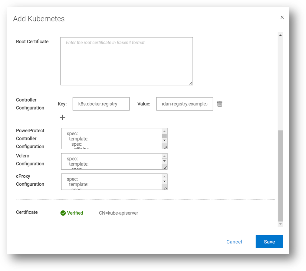
In this blog, we’ll go through some of the advanced options we’re enabling as part of the Kubernetes (K8s) asset source configuration in PowerProtect Data Manager (PPDM). These advanced parameters can be specified when adding a new K8s asset source or when modifying an existing one. Let’s look at some use cases and how PPDM can help.
Use Case 1: Internal registry
For a great first use case, let’s look at an advanced controller configuration. The advanced configuration, on the pod called ‘powerprotect controller,’ allows you to configure key-value pairs. There are nine pairs documented in the PowerProtect Kubernetes User Guide, but we will focus on the most important ones in this blog.
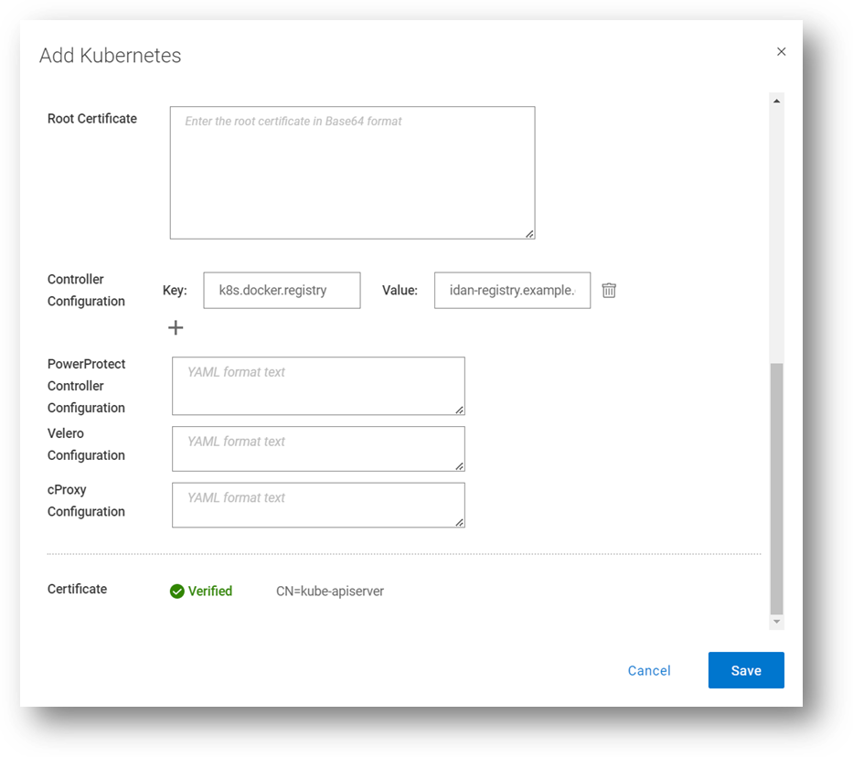
This one allows you to define an internal registry from which you can pull container images. By default, the required images are pulled from Docker Hub. For example:
Key: k8s.docker.registry
Value: idan-registry.example.com:8446
The value represents the FQDN of the registry, including the port as needed. Note that if the registry requires authentication, the k8s.image.pullsecrets key-value pair can be specified.
By the way, I’ve discussed the Root Certificate option in previous blogs. Take a look at PowerProtect Data Manager – How to Protect AWS EKS Workloads? and PowerProtect Data Manager – How to Protect GKE Workloads?.
Use Case 2: Exclude resources from metadata backup
The second use case we’ll look at enables the exclusion of Kubernetes resource types from metadata backup. It accepts a comma-separated list of resources to exclude. For example:
Key: k8s.velero.exclude.resources
Value: certificaterequests.cert-manager.io
Use Case 3: PowerProtect Affinity Rules for Pods
Another useful advanced option is the ability to customize any or all PowerProtect-related pods - powerprotect-controller, Velero, cProxy, and their configurations. The third use case we’ll cover is Affinity Rules.
Example 1 – nodeAffinity
The first example is nodeAffinity which allows you to assign any PowerProtect pod to a node with a specific node label.
This case may be suitable when you need to run the PowerProtect pods in specific nodes. For example, perhaps only some of the nodes have 10Gb connectivity to the backup VLAN, or only some of the nodes have connectivity to PowerProtect DD.
In the following example – any node with the app=powerprotect label can run the configured pod. This example uses the requiredDuringSchedulingIgnoredDuringExecution node affinity option, which means that the scheduler won’t run this pod on any node unless the rule is met.
Note: This must be in YAML format.
The configured pod is patched with the following configuration:
spec:
   template:
    spec:
      affinity:
        nodeAffinity:
           requiredDuringSchedulingIgnoredDuringExecution:
            nodeSelectorTerms:
            -   matchExpressions:
               - key: app
                 operator: In
                 values:
                  - powerprotect
Here’s another example, but this time with the preferredDuringSchedulingIgnoredDuringExecution node affinity option enabled. This means the scheduler tries to find a node that meets the rule, but if a matching node is not available the scheduler still schedules the pod.
spec:
  template:
    spec:
      affinity:
        nodeAffinity:
           preferredDuringSchedulingIgnoredDuringExecution:
            - weight: 1
              preference:
                matchExpressions:
                - key: app
                  operator: In
                  values:
                  - powerprotect
Here we can see how it is configured through the PowerProtect Data Manager UI, when registering a new K8s asset source, or when editing an existing one. In this screenshot, I’m updating the configuration for all the PowerProtect pods (powerprotect-controller, Velero, and cProxy), but it’s certainly possible to make additional config changes on any of these PowerProtect pods.
Example 2 – nodeSelector
Another much simpler example for node selection is nodeSelector. The pods would only be scheduled to nodes with the specified labels.
spec:
   template:
    spec:
      nodeSelector:
        app: powerprotect
Example 3 – nodeName
In this example we’ll examine an alternative way of assigning one of the PowerProtect pods to specific worker nodes.
spec:
   template:
    spec:
      nodeName: workernode01
Example 4 – Node Anti-affinity
The final example we’ll look at for nodeAffinity is anti-affinity, with operators including NotIn or DoesNotExist. The case for using anti-affinity is to enable scheduling the PowerProtect pods only to specific nodes that do not have a specific label or a certain role.
spec:
   template:
    spec:
      affinity:
        nodeAffinity:
           requiredDuringSchedulingIgnoredDuringExecution:
            nodeSelectorTerms:
            -   matchExpressions:
               - key: app
                 operator: NotIn
                 values:
                 - powerprotect
Use Case 4: Multus and custom DNS configuration
Another popular use case is Multus and custom DNS configuration. Multus is a Container Network Interface (CNI) plugin for Kubernetes that enables attaching multiple network interfaces to pods. I won’t elaborate too much on Multus’ features and capabilities here, but I’ll show some examples of how to customize the PowerProtect pod specs to accept multiple NICs and custom DNS configuration.
Example 1 – dnsConfig
spec:
   template:
    spec:
      dnsConfig:
        nameservers:
          - "10.0.0.1"
        searches:
          - lab.idan.example.com
          - cluster.local
Example 2 – Multus
metadata:
  annotations:
    k8s.v1.cni.cncf.io/networks: macvlan-conf
spec:
  template:
    spec:
      dnsConfig:
        nameservers:
          - "10.0.0.1"
        searches:
          - lab.idan.example.com
          - cluster.local
Always remember –documentation is your friend! The PowerProtect Data Manager Kubernetes User Guide has some useful information for any PPDM with K8s deployment.
Thanks for reading, and feel free to reach out with any questions or comments.
Idan
Author: Idan Kentor

Enhanced Installer Scripts to Protect Oracle Databases with PowerProtect Data Manager

Tue, 01 Aug 2023 19:09:43 -0000
|Read Time: 0 minutes
Our innovations and support for our customers never stop. We continue to provide extensive data protection support for Oracle databases with PowerProtect Data Manager, and the following installer script enhancements are now available with PowerProtect Data Manager version 19.14 onwards:
- Interactive single script execution to install or uninstall the Oracle RMAN agent and PowerProtect agent service as a root user
- Silent install or uninstall script using command line parameters to install or uninstall the Oracle RMAN agent and PowerProtect agent service as a root user.
Let’s dive in for more detailed information on these script enhancements.
Interactive single script execution to install the Oracle RMAN agent and PowerProtect agent service as a root user
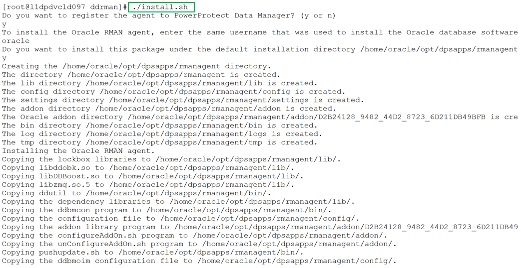
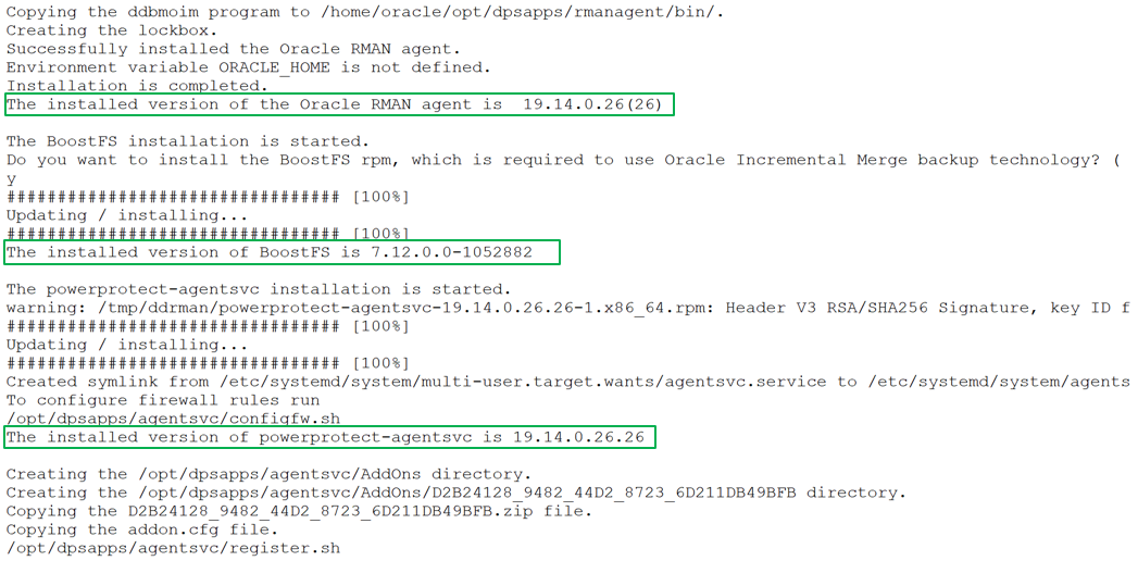
As a root user, you can use the install.sh script to install or update the Oracle RMAN agent, PowerProtect Agent Service, and BoostFS agent. This script also configures the Oracle add-on for PowerProtect Data Manager. These installations occur as a single script installation when run as a root user.
You can also run this script as a non-root user (Oracle User) to install the Oracle RMAN agent only.
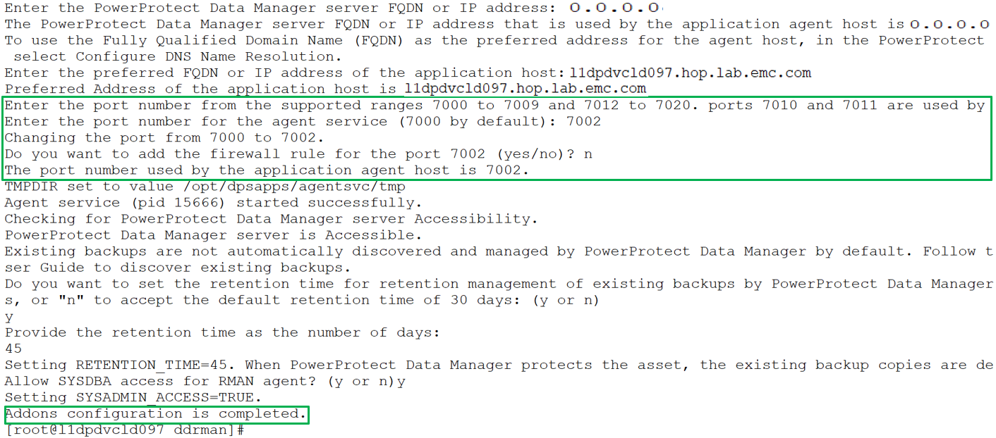
The install.sh script guides you through the installation process and requests input, where required, as shown in the following example installation:
You can specify the preferred FQDN or IP address of the Oracle RMAN agent host and the port to be used for communication between the Oracle RMAN agent and PowerProtect Data Manager. The specified port must be from the supported port ranges 7000 to 7009, and 7012 to 7020. The ports 7010 and 7011 are used by the agent service message bus.
Note: If you do not specify a port number, the default port 7000 is used as the PowerProtect Data Manager communication port.
Note: Run install.sh -h or install.sh --help to obtain more information about the script operation.
Silent install using command line parameters to install the Oracle RMAN agent and PowerProtect agent service as a root user
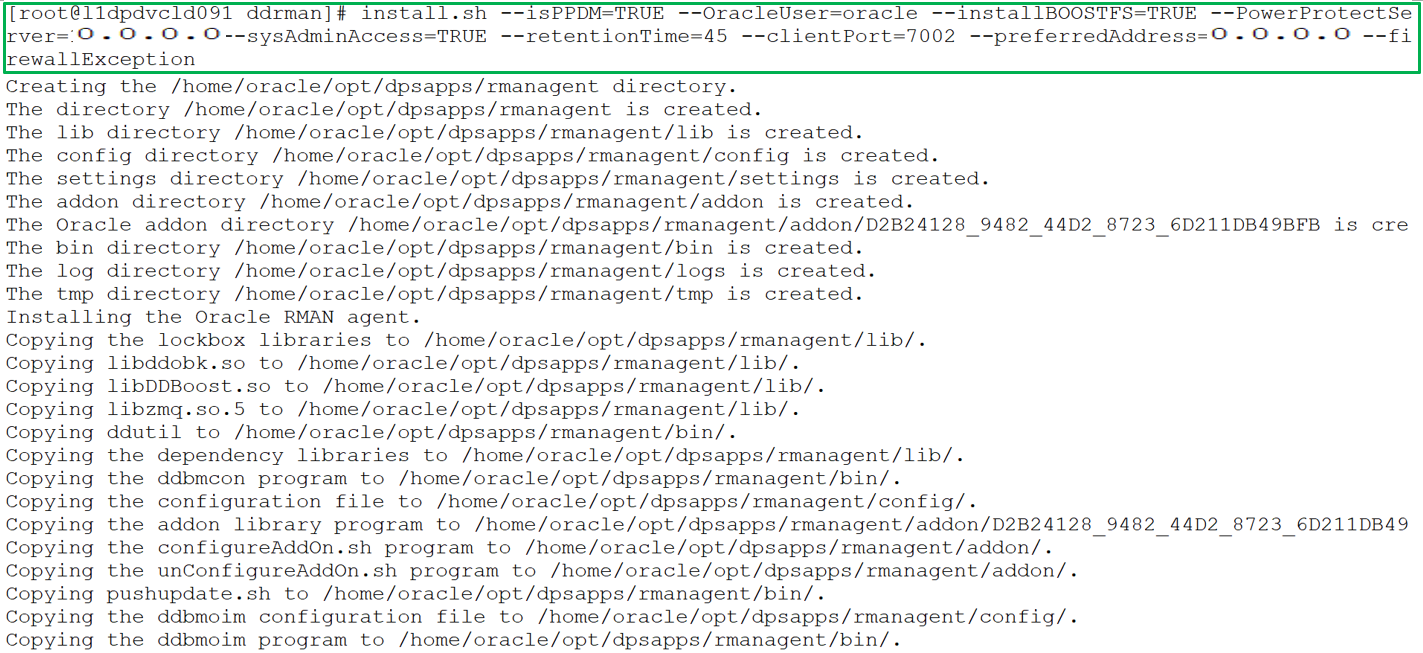
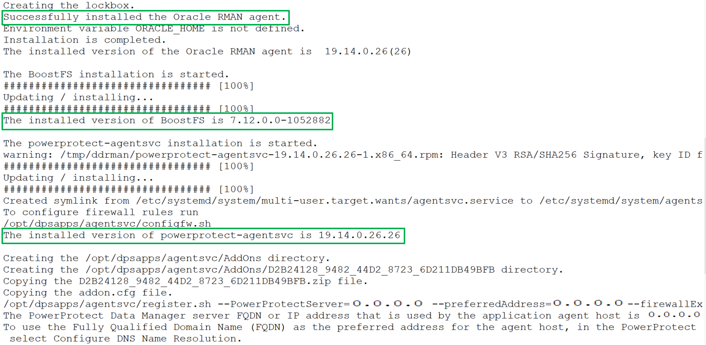
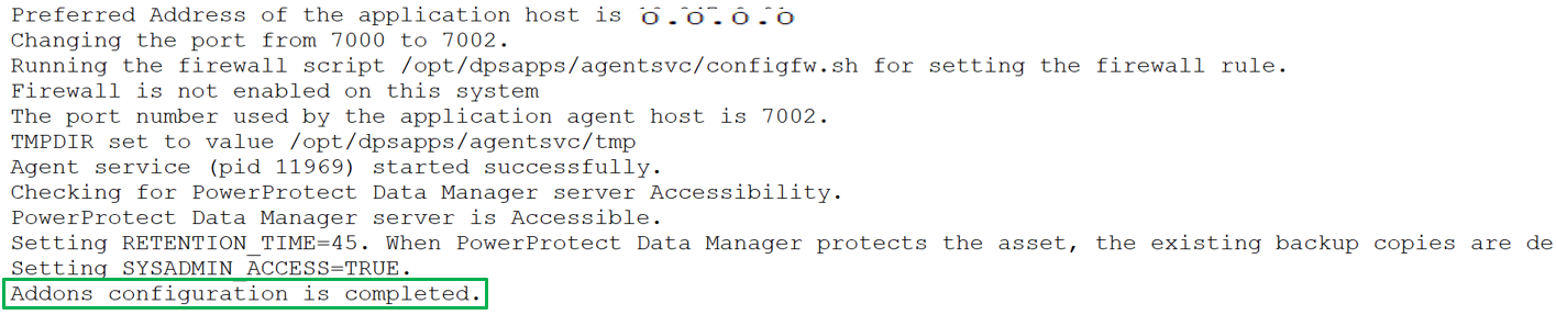
You can include multiple options in the install.sh command to perform a silent installation of the RMAN agent, PowerProtect agent service, and BoostFS agent, including add-on configurations. The install.sh script accepts command line parameters and environmental variables and the installation can run automatically without user interaction. Run install.sh -h or install.sh --help to see more information about the command line parameters and environmental variables.
For example, the following command installs and registers the Oracle RMAN agent with system administrator privileges, installs the PowerProtect Data Manager agent, and BoostFS package. The command options specify the preferred agent host address, communication port, and configuration of the firewall exception rule. It also specifies the retention time for Oracle RMAN agent backups.
Uninstall both Oracle RMAN agent and PowerProtect agent service as a root user
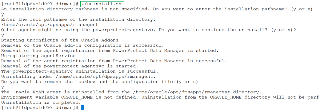
You can run the uninstall.sh script as a root user to uninstall both the Oracle RMAN agent and PowerProtect Data Manager agent in the same uninstallation session. The script also unconfigures the Oracle addons. The script can guide you through the uninstallation process but can also accept environmental variables to complete automatically the uninstallation process without user interaction.
The following example shows the sample uninstall script executed by a root user:
Notes:
- If other agents are installed on the application host, it is recommended to provide "n" for the prompt "Other agents might be using the powerprotect-agentsvc. Do you want to continue the uninstall?”
- Run uninstall.sh -h or uninstall.sh --help to obtain more information about the script operation.
With this efficient script enhancement, install, uninstall, and update operations can be done hassle-free as part of Oracle database protection.
For more details about Oracle database protection enhancements with Data Manager version 19.14, see our technical white paper PowerProtect Data Manager: Oracle RMAN Agent Backup and Recovery.
Author: Vinod Kumar Kumaresan, Principal Engineering Technologist, Data Protection Division

Kubernetes Application Consistency with PowerProtect Data Manager
Wed, 17 May 2023 15:56:55 -0000
|Read Time: 0 minutes
In this blog, let’s review application consistency for Kubernetes apps using PowerProtect Data Manager (PPDM).
PowerProtect Data Manager has been providing the ability to run pre/post K8s backup tasks (called hooks) for quite some time now. Now, these hooks can certainly quiesce the database running on K8s pods before the backup starts and end backup as a post-action for app-consistency, but these hooks can also be used to run pre/post actions on the pods as needed.
In this blog, I’ll also cover some use cases of app-consistency for K8s in PPDM and some advanced options. Hang tight, here we go.
Introduction and initial configuration
You can manage K8s application consistency in PowerProtect Data Manager by using the ppdmctl utility, which includes example application templates for the following databases:
- MySQL (standalone and cluster)
- PostgreSQL (standalone and cluster using helm chart)
- Cassandra (standalone)
- MongoDB (standalone and single shard cluster)
Obtain
You can obtain the ppdmctl utility through the PowerProtect Data Manager UI (under System Settings > Downloads > Kubernetes) or directly using the following URL:
https://<your-ppdm-host>/k8s-binaries-download?filename=/usr/local/brs/lib/cndm/misc/pptdmctl.tar.gz
Note that you need to login to the PPDM UI for this link to work.
You can also find the archive on the PPDM host itself at the following path: /usr/local/brs/lib/cndm/misc/ppdmctl.tar.gz
Run
In order to run ppdmctl, you’ll need to extract the archive, change directory, and make it executable:
tar zxvf ppdmctl.tar.gz
cd ppdmctl
chmod +x ppdmctl
Now, before we see how to apply an application template, let’s look at some useful commands:
ppdmctl help – shows the main help page
ppdmctl applicationtemplate --help – shows help for a specific command, applicationtemplate in this case
ppdmctl applicationtemplate apply --help – shows help for a specific flag, in this case applicationtemplate apply
ppdmctl completion bash | sudo tee -a /etc/bash_completion.d/ppdmctl – applies autocompletion. Note that in this case we’re applying the BASH flavor but Fish, PowerShell and Zsh are also available.
Applying Application Templates
You can apply an application template using the following command, for example by using one of the MySQL example templates:
ppdmctl applicationtemplate apply -i examples/mysqlapptemplate.yaml -n mysqlApplying an application template creates an applicationtemplates.powerprotect.dell.com CR:
kubectl get applicationtemplates -n mysqlNAME AGE mysql 1d
Application Templates Structure
Let’s have a look at the one of the included example application templates for MongoDB:
cat mongodbapptemplate1sts.yaml
apiVersion: "powerprotect.dell.com/v1beta1"
kind: ApplicationTemplate
metadata:
    name: mongodbtemplate
     namespace: mongodb-helm
spec:
    enable: true
    type: "MONGODB"
    appLabel: "app.kubernetes.io/name:mongodb"
     appActions:
       Pod:
            preHook:
                command: '["/bin/sh", "-c", "mongo -u root -p $MONGODB_ROOT_PASSWORD $MONGODB_PRIMARY_ROOT_PASSWORD --eval \"db.fsyncLock()\""]'
            postHook:
                command: '["/bin/sh", "-c", "mongo -u root -p $MONGODB_ROOT_PASSWORD $MONGODB_PRIMARY_ROOT_PASSWORD --eval \"db.fsyncUnlock()\""]'
       StatefulSet:
            selectors:
               - selectorTerms:
                    - field: "Name"
                      selectorExpression: ".*-[1-9][0-9]*$"
               - selectorTerms:
                    - field: "Name"
                      selectorExpression: ".*-0$"
Check out the following list for some guidance about the structure and format of app templates. Later in this blog we’ll explore more settings.
- The apiVersion, kind, metadata and spec fields are all mandatory.
- The app template can be provided in a YAML or JSON format.
- The namespace specified must exist and match the only one specified when creating or applying the app template with ppdmctl.
- The type field under spec must match the type specified when applying or creating the app template using ppdmctl.
- appLabel must be specified and should preferably match a single pod on the specified namespace. You can confirm the appropriate label with the following kubectl command:
kubectl get pods -n <your-ns> --show-labels6. appActions is required and must include Pod and optionally the StatefulSet or Deployment parameters.
7. Either or both preHook and postHook are required.
8. Either the preHook or postHookcommand must be provided as a JSON array. Here are some examples:
- command: '[\"/usr/bin/backup_script\", \"--file\", \"/backups/backup.tgz\"]'
- command: '["/bin/sh", "-c", "mysql -uroot -p$(cat $MYSQL_ROOT_PASSWORD_FILE $MYSQL_MASTER_ROOT_PASSWORD_FILE) -e \"FLUSH TABLES WITH READ LOCK; FLUSH LOGS;SELECT SLEEP(100);\"\"]'
- command: '[\"/bin/sh\", \"-c\", \"BACKUPDIR=/db/backups ;SERVER=localhost; curl -XPOST http://$SERVER:9090/api/v1/admin/tsdb/snapshot;\"]'
9. If you need to exclude PVCs from protection, make sure that all PVCs that are being used by the backed-up pods are included in the backup. Inclusion/exclusion of PVCs can be configured as part of the protection policy, either when creating a new protection policy through the PPDM UI/ REST API or when editing an existing policy.
Using multiple labels
In some cases there are multiple pods that will be matched by a single label. For example, when multiple instances of the MySQL database are provisioned, app=mysql would result in many matched pods. In such cases, you can specify multiple values under appLabel as key-value pairs in a comma-separated list, as in the following examples:
- appLabel: "mariadb-master:yes,app:mariadbprod1"
- appLabel: "app.kubernetes.io/name:mongodb,component=mongo"
Running on a specific container
This use case is quite important for multi-container pods. If you need to run pre/post commands on a specific container on a given pod, you can specify that container under Pod, in the same block as the command. Note that by default the first container is being used unless the container parameter is specified. Check out the following example:
kubectl get pods -n mariadb
NAME            READY   STATUS     RESTARTS   AGE
mariadb-sts-0   2/2     Running    0          20d
kubectl get pods -n mariadb mariadb-sts-0 -o jsonpath='{.spec.containers[*].name}'
mariadb maria-tools-sidecar
cat mariadbapptemplate.yaml
apiVersion: "powerprotect.dell.com/v1beta1"
kind: ApplicationTemplate
metadata:
    name: mariadbtemplate
     namespace: mariadb
spec:
    type: "MARIADB"
    enable: true
    appLabel: "mariadb-master:yes,app:mariadbprod1"
     appActions:
       Pod:
            preHook:
                command: "[\"/bin/sh\", \"-c\", \"export BACKUPDIR=/var/lib/mysql/backups; if ls $BACKUPDIR/*_full.bak 1> /dev/null 2>&1; then mariabackup --backup --stream=mbstream --extra-lsndir=$BACKUPDIR/backup_incr --incremental-basedir=$BACKUPDIR/backup_base --user=root --password=$MARIADB_ROOT_PASSWORD | gzip --rsyncable > $BACKUPDIR/backup.$(date +%F_%R:%S)_incr.bak; else mariabackup --backup --stream=mbstream --extra-lsndir=$BACKUPDIR/backup_base --user=root --password=$MARIADB_ROOT_PASSWORD | gzip --rsyncable > $BACKUPDIR/backup.$(date +%F_%R:%S)_full.bak; fi; exit $?\"]"
                container: "mariadb"
…
Timeout
Another important capability is controlling the command timeout which can be performed by specifying the timeout parameter. By default, each command has a timeout of 30 seconds. For cases where there is a risk that the command might take longer, the timeout parameter can be specified. This especially relevant for DB dump / backup processes.
For example, let’s look at the first app template but this time with the timeout parameter:
apiVersion: "powerprotect.dell.com/v1beta1"
kind: ApplicationTemplate
metadata:
    name: mongodbtemplate
     namespace: mongodb-helm
spec:
    enable: true
    type: "MONGODB"
    appLabel: "app.kubernetes.io/name:mongodb"
     appActions:
       Pod:
            preHook:
                command: '["/bin/sh", "-c", "mongo -u root -p $MONGODB_ROOT_PASSWORD $MONGODB_PRIMARY_ROOT_PASSWORD --eval \"db.fsyncLock()\""]'
                timeout: 60
…
Behavior upon failure
The final advanced capability I want to talk about today is onError. OnError defaults to Fail but Continue is another possible value which means that if a certain pre or post hook fails then the backup flow carries on.
Here’s the last application template but with the OnError parameter this time:
apiVersion: "powerprotect.dell.com/v1beta1"
kind: ApplicationTemplate
metadata:
    name: mongodbtemplate
     namespace: mongodb-helm
spec:
    enable: true
    type: "MONGODB"
    appLabel: "app.kubernetes.io/name:mongodb"
     appActions:
       Pod:
            preHook:
                command: '["/bin/sh", "-c", "mongo -u root -p $MONGODB_ROOT_PASSWORD $MONGODB_PRIMARY_ROOT_PASSWORD --eval \"db.fsyncLock()\""]'
                timeout: 60
                onError: Continue
…
Always remember – the documentation is your friend. Specifically, the PowerProtect Data Manager Kubernetes User Guide has some useful information for any PPDM with K8s deployment.
Feel free to reach out with any questions or comments.
Thanks for reading,
Idan
Author: Idan Kentor

Flexible Windows Bare-Metal Recovery with PowerProtect Data Manager
Tue, 24 Jan 2023 11:00:27 -0000
|Read Time: 0 minutes
In today’s enterprise, it is certainly not a surprise to hear of a mission-critical application server experiencing downtime or degraded state due to disaster recovery situations, such as hardware failures and cyberattacks. In such situations, bare-metal recovery (BMR) is obviously one of the best disaster recovery solutions. Most users rely on the BMR procedure to restore mission-critical applications, operating environments, and data.
With Dell PowerProtect Data Manager, BMR for a Windows server can be performed efficiently with just a few clicks. Before we explore more about Windows server BMR with PowerProtect Data Manager, let us briefly take a look at BMR.
What is BMR?
BMR, also known as offline recovery, is used as part of a disaster recovery plan that provides protection when a server or a computer will not start after a catastrophic failure. The term bare metal is in reference to a computer without a base operating system or applications. The goal of BMR is to bring a server or computer to the state it was in before the failure.
When is BMR required?
BMR can be used to recover from the following situations:
- To recover a server or a computer entirely after a hardware failure that has been repaired.
- To recover data to a new server or a computer after a hardware failure that cannot be repaired. The new computer does not have an operating system, and the operating system files must also be recovered from the old computer.
BMR of Windows host with PowerProtect Data Manager
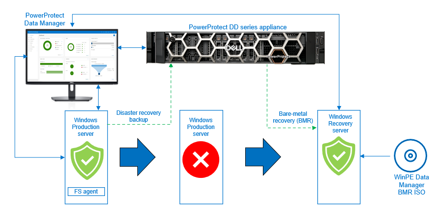
Starting with version 19.10, PowerProtect Data Manager supports the file system agent to back up the disaster recovery asset and perform a BMR of a Windows host.
You can use BMR for the following operations:
- Physical machine to physical machine (P2P)
- Physical machine to virtual machine (P2V)
- Virtual machine to virtual machine (V2V)
With PowerProtect Data Manager, you can perform BMR by backing up the disaster recovery asset. When a file system agent backup is performed, there is an extra asset—”disaster recovery”—that is backed up. This asset includes the information required to rebuild the Windows system back to its state at the time of the backup. The data in the disaster recovery asset, plus volume information for those file systems that contain operating system data (critical volumes), are also backed up.
After the disaster recovery asset backup is successful, you can perform the BMR using the customized PowerProtect Data Manager WinPE ISO image. By default, each BMR backup is system state enabled.
Backing up Windows disaster recovery assets
After you install the file system agent on the Windows file system host and it is approved in the PowerProtect Data Manager UI, the disaster recovery asset is discovered along with the other file system assets.
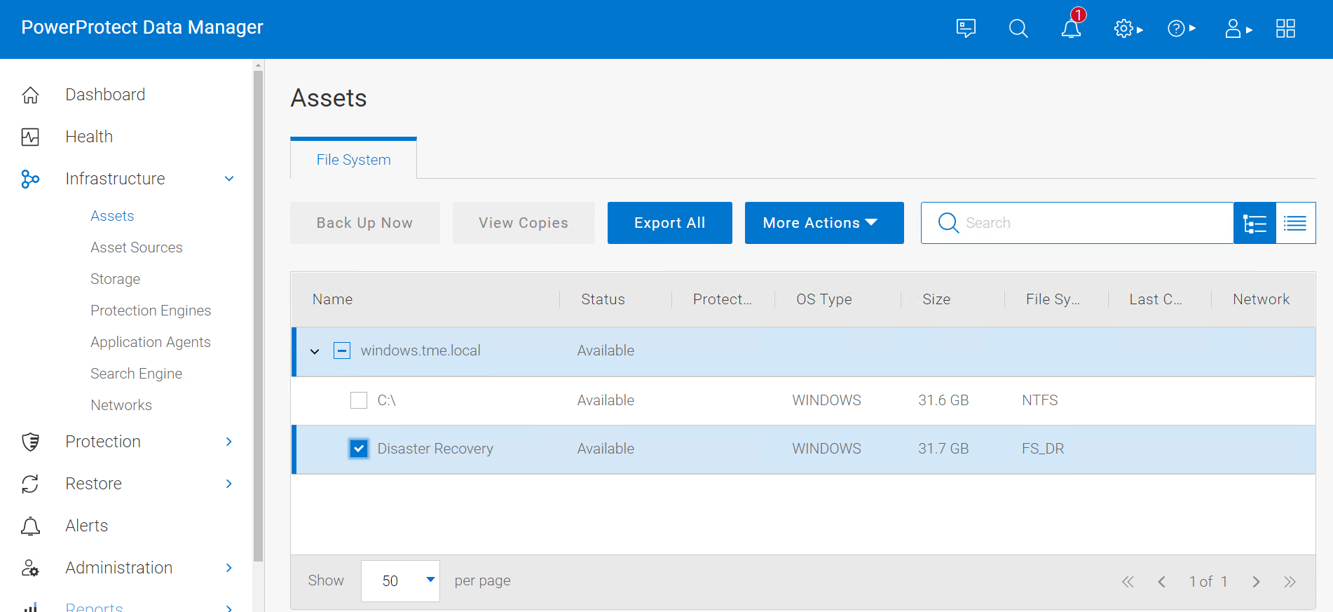
After the disaster recovery asset is discovered in PowerProtect Data Manager UI, you can create a file system protection policy and configure it to back up the disaster recovery asset. A disaster recovery protection policy should contain objects to be backed up, which include critical volumes and system state recovery files.
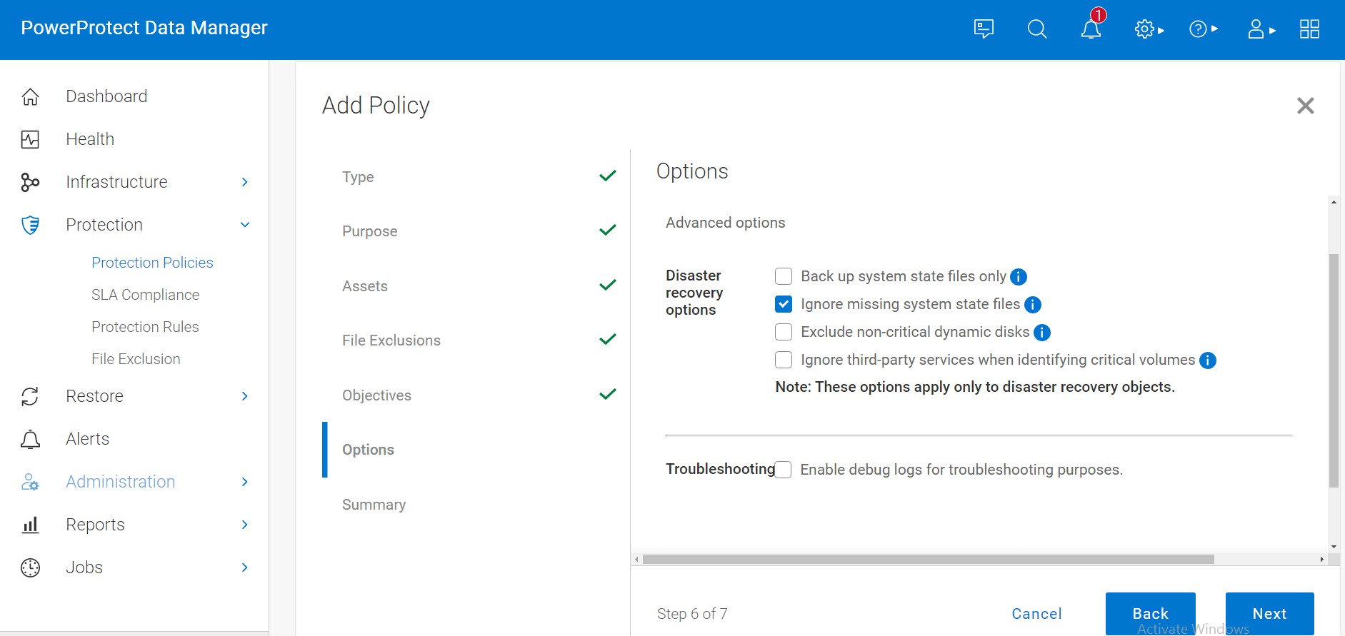
After the disaster recovery asset backup is successful, you can perform BMR using the customized PowerProtect Data Manager WinPE ISO image.
BMR data consists of the following:
- The operating system files and all data except user data on critical volumes
Note: Critical volumes include the boot volume, the system volume, and the volume that hosts system state data, such as Active Directory and application services.
- All system state information
By default, each BMR backup is system state enabled.
To protect a Windows host entirely, we recommend that you back up BMR data for critical volumes and separately back up regular assets that contain user data.
Performing Windows BMR
PowerProtect Data Manager provides a custom WinPE image that allows you to recover a source host to a target host without installing an operating system. Because local disks are not in use by the operating system, the recovery process can replace files without conflict. The custom PowerProtect Data Manager WinPE image is based on Windows PE 10.0 and contains the NIC and disk drivers for the Windows versions that the WinPE image supports.
Before you perform a BMR, verify that the environment meets the requirements and that you have the necessary information.
Note: For BMR requirements, see the the PowerProtect Data Manager File System User Guide.
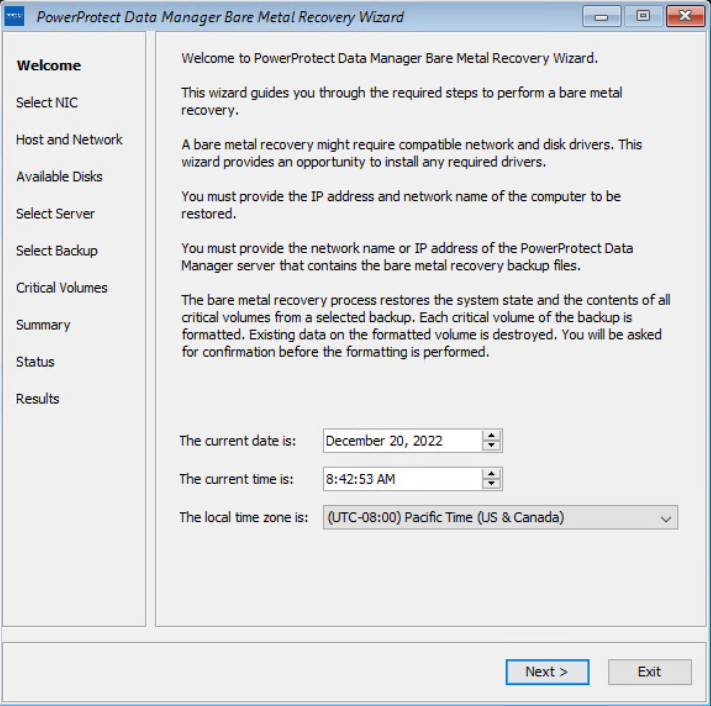
When a recovery of a system is required, you can download the Windows BMR ISO image from the PowerProtect Data Manager UI. The image contains the necessary files to boot and create a WinPE system. The image includes a PowerProtect Data Manager Bare Metal Recovery Wizard that is launched and used as part of the restore.
Note: Ensure that the hardware on the target computer is operational and that the target computer is similar in make, model, and hardware configuration to the source computer to be recovered. For more details about the BMR requirements, see the PowerProtect Data Manager File System User Guide.
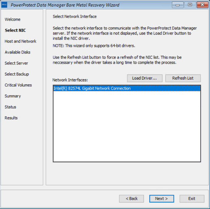
The target host boots with the custom WinPE image, either locally or over the network. The Welcome page of the PowerProtect Data Manager Bare Metal Recovery Wizard is displayed.
On the Select NIC page, you can select the network interface for communication with Data Manager during the BMR. If the required NIC driver is not in the list, click Load Driver to browse to it.
Note: The driver must not require a restart. The WinPE environment loads only in memory, and changes are not persistent across a restart. If a restart prompt appears, you might be able to ignore the prompt. Most NIC drivers are plug-and-play.
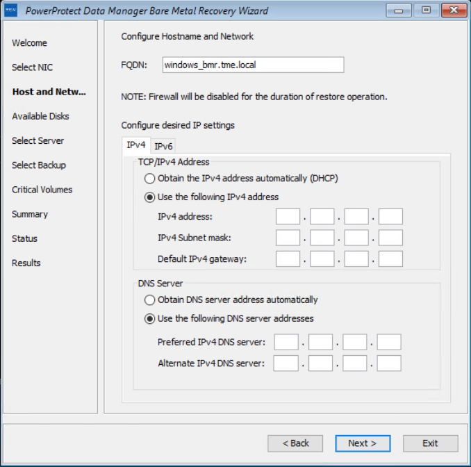
On the Host and Network Configuration page, enter the hostname of the target host and the domain name for the host.
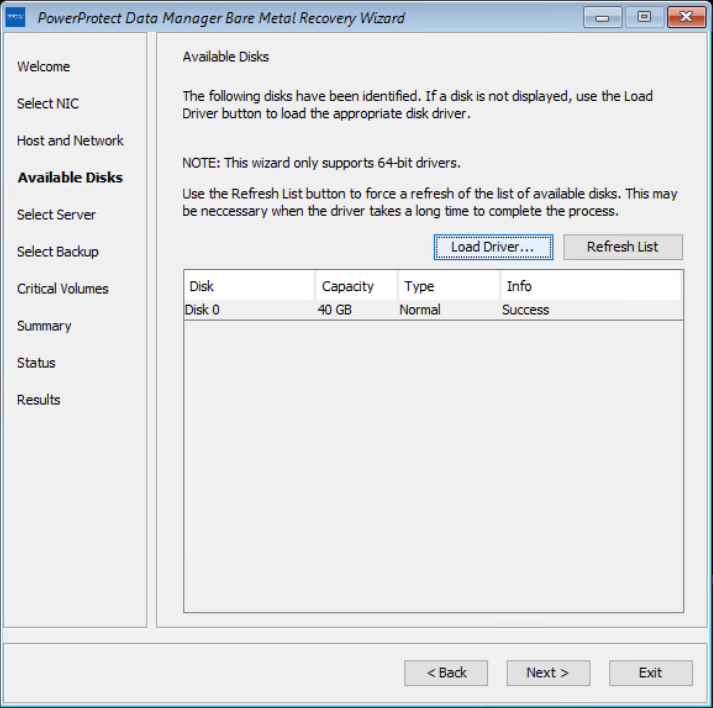
On the Available Disks page, verify the disk configuration. The size and number of hard disks that are added to the target machine should be either equal to or greater than the size and number of disks on the source machine.
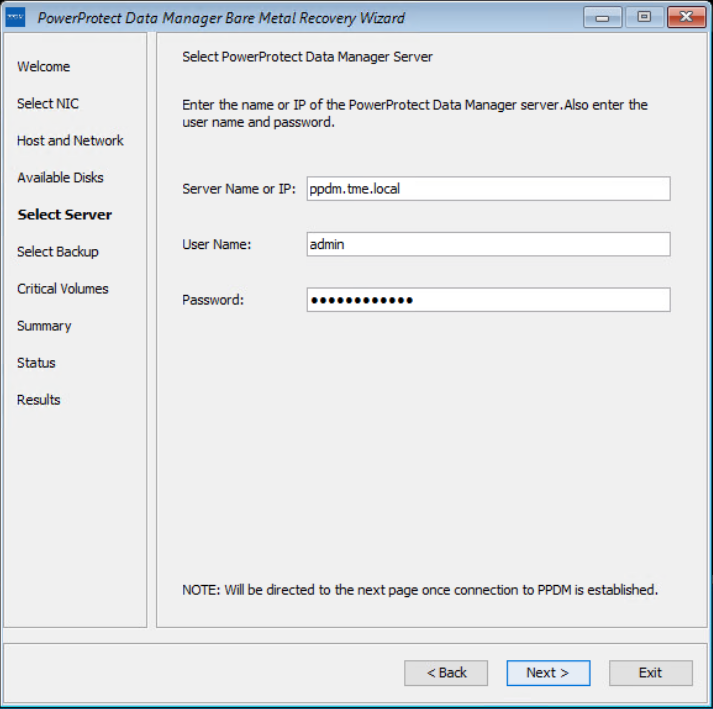
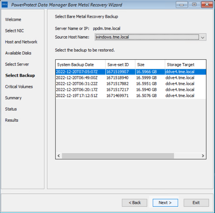
On the Select Server page, enter the PowerProtect Data Manager server and source hostname details. In the Server Name or IP field, add the IP of the server or FQDN only.
On the Select Backup page, select the respective host from the Source Host Name list and BMR data to restore to the destination host. Backups appear in the list in descending order from the most to least recent.
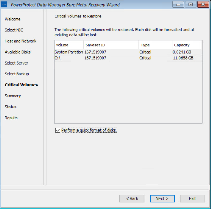
The Critical Volumes page displays the volumes that will be restored and the option to enable a quick disk format.
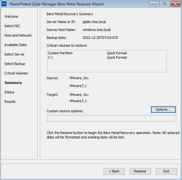
The PowerProtect Data Manager BMR wizard fetches information to perform a BMR, and the Summary page is displayed. To add custom BMR options, next to Custom restore options, click Options.
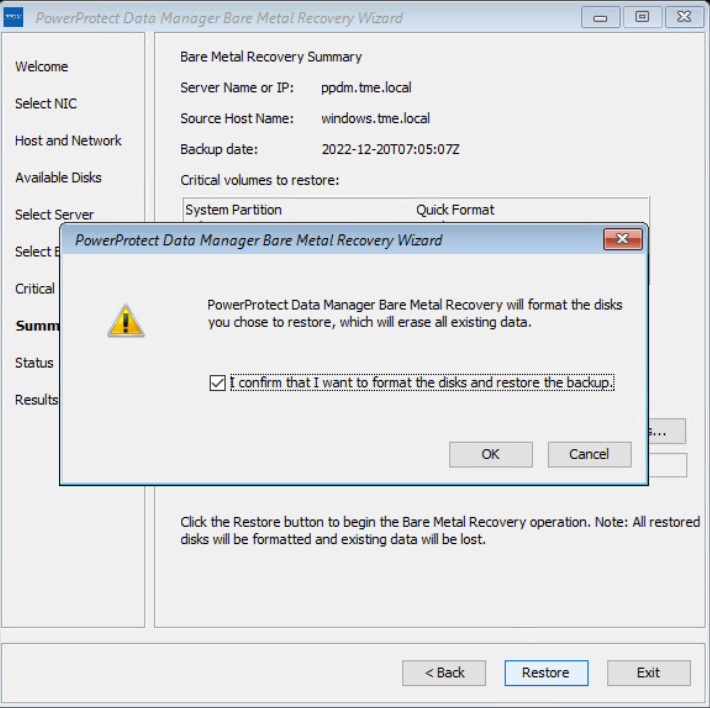
Confirm the quick format of disks and restore the backup.
The Status page shows the restore progress.
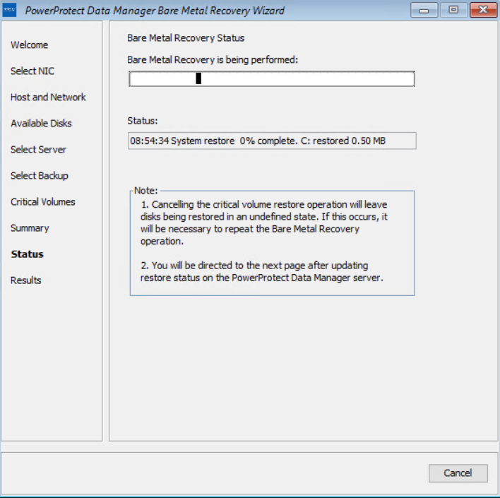
You can also monitor the Bare Metal Recovery job status in the PowerProtect Data Manager UI at Jobs > Protection Jobs.
The BMR wizard displays the results. After the recovery is successful, you can reboot the system and restore the application data as required.
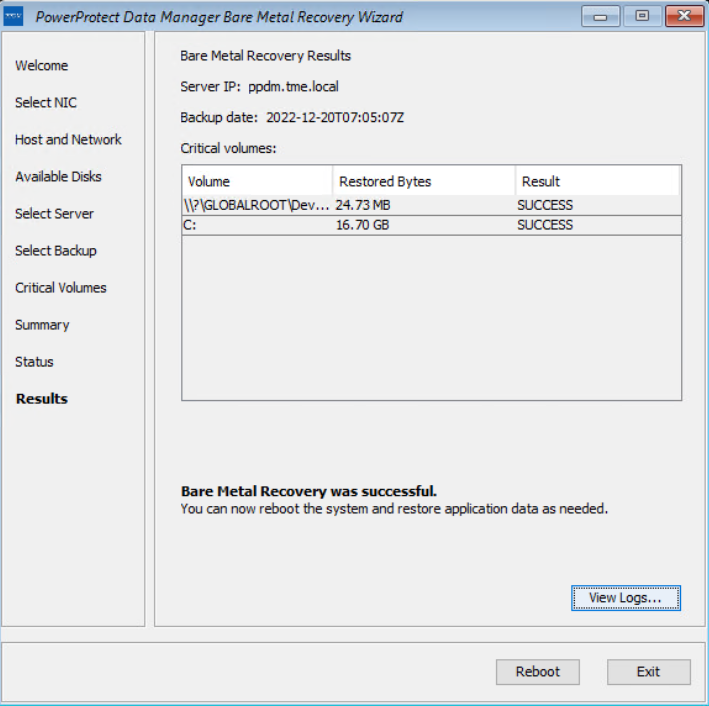
With this easy BMR solution with PowerProtect Data Manager, Dell Technologies empowers Windows administrators to recover their business-critical Windows servers quickly and resume their operations.
For more details about disaster recovery for Windows with PowerProtect Data Manager, see the technical white paper and PowerProtect Data Manager: File System User Guide.
For more details about data protection with PowerProtect Data Manager, see the PowerProtect Data Manager website.
Author: Vinod Kumar Kumaresan, Principal Engineering Technologist, Data Protection Division

PowerProtect Data Manager – How to Protect GKE (Google Kubernetes Engine) Workloads?
Mon, 05 Dec 2022 20:31:24 -0000
|Read Time: 0 minutes
As I said in my previous blog on EKS protection, the topic of Kubernetes protection is something I’m asked quite often. GKE is no different so why not publish another blog just for GKE protection in PPDM? Expect more blogs on these topics soon 😊.
Back to the topic at hand - GKE protection with PPDM. When talking about PPDM Protection of GKE workloads, the following pillars come to mind:
- GKE Cluster deployment
- Deployment of PowerProtect Data Manager and PowerProtect DD
- General Preparations
- GKE Preparations
- Add GKE to PowerProtect Data Manager
First, let’s briefly discuss the tools we need to install for managing GKE:
- kubectl – a command line tool to work with Kubernetes clusters
- Google Cloud CLI – gcloud is a command line management tool for working with Google Cloud resources. For installation instructions and other info, see gcloud CLI overview.
GKE Deployment
You can configure GKE clusters by using the Google Cloud console, the command line (gcloud), or REST. Documentation is your friend: https://cloud.google.com/kubernetes-engine/docs.
In my specific case, some fundamental configuration elements include the following:
- An enabled Kubernetes Engine API.
- A standard cluster deployment model
- Project-level constraints dictate using a specific region
- Zonal with a specific Region. Select Regional for multi-zonal configuration. Note that even with Zonal, the nodes can have a default location that is different from the control plane node (to increase availability). Note that in multi-zonal configurations, the configured number of nodes is set per zone.
- A project constraint: no public IPs allowed. I’ve therefore configured a private cluster but enabled external access to the control plane by selecting ‘Access control plane using its external IP address’.
- Configured a subnet for this GKE cluster with two additional secondary subnets. To keep things simple, I’ve configured this subnet on the same VPC network as the PPDM and DD subnet.
- Specified a control plane IP range that does not overlap with any subnet of the cluster VPC.
- Configured network parameters under the cluster networking level in the Google Cloud console. Configuring Pod Address Range though the node pool section would overwrite settings on the cluster level.
- Pay attention to the control plane version. Go with ‘Static channel’ to control the K8s version being used – it can still be upgraded automatically for security and compatibility, but it is not managed automatically by GKE as the Release channel is. In this case, I’ve opted to use the Static channel with the latest available release (K8s 1.24).
- Deployed a node pool with four nodes. Make sure to size the number of nodes and their specs in accordance with the workload that is going to be deployed and scale as needed. Watch out for pods in an “PodUnschedulable” status, especially as the powerprotect-controller and velero pods are rolled out after asset source discovery at the end of this blog.
- Make sure to enable ‘Compute Engine Persistent Disk CSI Driver’.
I’ve used the following gcloud command to deploy my GKE cluster (not the shortest command you’re ever going to run, but an effective one 😊):
gcloud container --project "gcp-dev-idan-pte" clusters create "idan-cluster-1" --region "us-east1-a" --no-enable-basic-auth --cluster-version "1.24.6-gke.1500" --release-channel "None" --machine-type "e2-medium" --image-type "COS_CONTAINERD" --disk-type "pd-balanced" --disk-size "100" --metadata disable-legacy-endpoints=true --scopes "https://www.googleapis.com/auth/cloud-platform" --max-pods-per-node "110" --num-nodes "4" --logging=SYSTEM,WORKLOAD --monitoring=SYSTEM --enable-private-nodes --master-ipv4-cidr "10.10.0.0/28" --enable-ip-alias --network "projects/gcp-dev-idan-pte /global/networks/gke" --subnetwork "projects/gcp-dev-idan-pte/regions/us-east1/subnetworks/gke1" --cluster-secondary-range-name "secondary2" --services-secondary-range-name "secondary" --no-enable-intra-node-visibility --default-max-pods-per-node "110" --no-enable-master-authorized-networks --addons HorizontalPodAutoscaling,HttpLoadBalancing,GcePersistentDiskCsiDriver --no-enable-autoupgrade --enable-autorepair --max-surge-upgrade 1 --max-unavailable-upgrade 0 --enable-shielded-nodes
Deploying PowerProtect
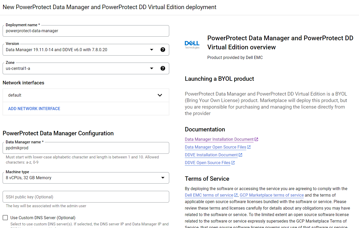
Deploying PowerProtect Data Manager and PowerProtect DD is a piece of cake. We just need to launch the deployment of PowerProtect Data Manager and PowerProtect DD Virtual Edition from the marketplace, provide the zone to deploy on, provide the network and subnet to deploy them, and optionally provide IP addresses for PPDM, DDVE, and DNS. This deployment process provisions the instances and rules for both PowerProtect Data Manager and PowerProtect DD. PowerProtect DD can be deployed separately or along with PPDM. (Remember that the newly deployed PowerProtect Data Manager can also leverage an existing PowerProtect DDVE.)
For more info, see Dell PowerProtect Data Manager: Deployment and Configuration on Google Cloud.
GKE Preparations
General
1. To configure the gcloud CLI, run the following command:
gcloud init
2. List your GKE clusters:
gcloud container clusters list --region <region-id>
3. To use the new gcloud auth plugin, enter:
gcloud components install gke-gcloud-auth-plugin
Note: You might need to run additional commands depending on the OS type you’re using so just follow the on-screen instructions.
4. Configure kubectl to interact with your GKE cluster:
gcloud container clusters get-credentials <your-gke-cluster-name>
5. Verify that kubectl works with your cluster:
kubectl get nodes
6. List CSI drivers and make sure that the Compute Engine Persistent Disk CSI Driver (pd.csi.storage.gke.io) is installed:
kubectl get csidrivers
7. List all storage classes:
kubectl get storageclasses
Storage and volume snapshot classes
In this blog, we are leveraging the ‘standard-rwo’ storage class. Although other storage classes can be created and used, make sure to use the pd.csi.storage.gke.io provisioned. Avoid using the legacy (deprecated) kubernetes.io/gce-pd in-tree storage plugin.
8. Create the Volume Snapshot Class YAML file:
cat <<EOF | tee snapclass-standard-rwo.yaml
apiVersion: snapshot.storage.k8s.io/v1
kind: VolumeSnapshotClass
metadata:
  name: standardrwo-pd-snapclass
driver: pd.csi.storage.gke.io
deletionPolicy: Delete
parameters:
   storage-locations: <your-region>
EOF
Make sure to provide the relevant region (such as us-east1) on which GKE runs under the ‘storage-locations’ parameter. It’s not just recommended from a performance standpoint but also for cases where there are project-level constraints that are set to limit resources to a specific region, or where there is a need to stick to a specific region.
9. Create the snapshot class:
kubectl apply -f snapclass-standard-rwo.yaml
10. Make sure it got created:
kubectl get volumesnapshotclass
11. Patch the standard storage class to remove the default setting:
kubectl patch storageclass standard -p "{\"metadata\": {\"annotations\":{\"storageclass.kubernetes.io/is-default-class\":\"false\"}}}"12. Set standard-rwo as the default storage class:
kubectl patch storageclass standard -p "{\"metadata\": {\"annotations\":{\"storageclass.kubernetes.io/is-default-class\":\"true\"}}}"13. Make sure that standard-rwo shows up as the default storage class:
kubectl get sc
PowerProtect K8s container images
For private GKE clusters, we would need to add the PowerProtect-required container images to a registry. The GKE cluster at hand would be able to pull images from this registry, but because they are hosted on Docker Hub, the images wouldn’t be available to a private cluster. This means that we would need to have a registry such as Google Container Registry (GCR) or Google Artifact Registry available. In this blog, I will be providing examples of how to work with Google Artifact Registry.
14. The required container images are:
- dellemc/powerprotect-k8s-controller
- dellemc/powerprotect-cproxy
- dellemc/powerprotect-velero-dd
- velero/velero
- vsphereveleroplugin/velero-plugin-for-vsphere (for K8s clusters on vSphere that use VMware CSI - irrelevant to GKE and shouldn’t be pulled from the registry)
- vsphereveleroplugin/backup-driver (irrelevant to GKE and shouldn’t be pulled)
15. The versions of these required container images might differ from one PPDM release to another. The supported versions of PPDM 19.12.0-9 are:
dellemc/powerprotect-k8s-controller:19.12.0-19
dellemc/powerprotect-cproxy:19.12.0-19
dellemc/powerprotect-velero-dd:19.12.0-19
velero/velero:1.9.1
Note: The image requirements for the respective PPDM release can be found in the following file on the PPDM server:
/usr/local/brs/lib/cndm/config/k8s-image-versions.info
16. On the same host that is running kubectl and gcloud, add credentials for Docker authentication to the Registry:
gcloud auth configure-docker us-east1-docker.pkg.dev
Be sure to specify the appropriate region.
17. Enable the Artifact Registry API as needed:
gcloud services enable artifactregistry.googleapis.com
18. Create the Artifact repository:
gcloud artifacts repositories create ppdm --repository-format=docker --location=us-east1
19. Pull the images by running the following commands:
docker pull dellemc/powerprotect-k8s-controller:19.12.0-19
docker pull dellemc/powerprotect-cproxy:19.12.0-19
docker pull dellemc/powerprotect-velero-dd:19.12.0-19
docker pull velero/velero:v1.9.1
20. Tag and push the images to the Artifact repository. Be sure to modify the project name:
docker tag dellemc/powerprotect-k8s-controller:19.12.0-19 us-east1-docker.pkg.dev/gcp-dev-idan-pte/ppdm/dellemc/powerprotect-k8s-controller:19.12.0-19

docker push us-east1-docker.pkg.dev/gcp-dev-idan-pte/ppdm/dellemc/powerprotect-k8s-controller:19.12.0-19

docker tag dellemc/powerprotect-cproxy:19.12.0-19 us-east1-docker.pkg.dev/gcp-dev-idan-pte/ppdm/dellemc/powerprotect-cproxy:19.12.0-19

docker push us-east1-docker.pkg.dev/gcp-dev-idan-pte/ppdm/dellemc/powerprotect-cproxy:19.12.0-19

docker tag dellemc/powerprotect-velero-dd:19.12.0-19 us-east1-docker.pkg.dev/gcp-dev-idan-pte/ppdm/dellemc/powerprotect-velero-dd:19.12.0-19

docker push us-east1-docker.pkg.dev/gcp-dev-idan-pte/ppdm/dellemc/powerprotect-velero-dd:19.12.0-19

docker tag velero/velero:v1.9.1 us-east1-docker.pkg.dev/gcp-dev-idan-pte/ppdm/velero/velero:v1.9.1

docker push us-east1-docker.pkg.dev/gcp-dev-idan-pte/ppdm/velero/velero:v1.9.1
21. Verify that all images are available on the repository:
gcloud artifacts docker images list us-east1-docker.pkg.dev/gcp-dev-idan-pte/ppdm
Add GKE to PowerProtect Data Manager
Finally, let’s add our GKE cluster to PPDM. Follow these steps to gather some information and register GKE to PPDM.
1. Get the K8s cluster control-plane endpoint:
kubectl cluster-info
2. For private clusters with external control plane, run the following command to obtain the private endpoint:
gcloud container clusters describe <your-gke-cluster-name> --zone <your-zone> | grep privateEndpoint
3. To create a service account on the GKE cluster for PPDM discovery and operations, PPDM RBAC YAML files need to be applied.
a. Retrieve the rbac.tar.gz file from the PPDM appliance at the following location:
/usr/local/brs/lib/cndm/misc/rbac.tar.gz
b. In PPDM 19.12, download the archive from the PowerProtect Data Manager UI (under System Settings > Downloads > Kubernetes) or directly using the following URL:
https://<your-ppdm-server>/k8s-binaries-download?filename=/usr/local/brs/lib/cndm/misc/rbac.tar.gz
Note that the link will only work if you’re logged into the PPDM UI. You can also find the archive on the PPDM server itself at the following path: /usr/local/brs/lib/cndm/misc/rbac.tar.gz
c. Extract the archive, navigate to the rbac directory, and apply the two YAML files using the following commands:
kubectl apply -f ppdm-discovery.yaml
kubectl apply -f ppdm-controller-rbac.yaml
d. If you’re using K8s 1.24 or later, you must manually create the secret for the PPDM discovery storage account:
kubectl apply -f - <<EOF
apiVersion: v1
kind: Secret
type: kubernetes.io/service-account-token
metadata:
  name: ppdm-discovery-serviceaccount-token
  namespace: powerprotect
  annotations:
    kubernetes.io/service-account.name: "ppdm-discovery-serviceaccount"
EOF
e. Retrieve the secret key:
kubectl describe secret $(kubectl get secret -n powerprotect | awk '/disco/{print $1}') -n powerprotect | awk '/token:/{print $2}'4. Retrieve the GKE cluster root CA:
gcloud container clusters describe <your-gke-cluster-name> --zone <your-zone> | grep -i clustercacert | awk '{print $2}'For cases like mine where PPDM does not have an external IP, we can configure a Launch Pad VM and connect to it using IAP (Identity Aware Proxy). Here are some high-level steps:
5. Create a Windows Launch Pad VM using the Google Cloud console or by running the following command:
gcloud compute instances create win2k22lp1 --machine-type=e2-medium --scopes=cloud-platform --enable-display-device --image-family=windows-2022 --image-project=windows-cloud --boot-disk-size=50GB --zone us-east1-a --network=gke --subnet=gke1 --no-address
Make sure to alter the network, subnet, and zone as needed.
6. Set the Windows password by using either the Google Cloud console or the CLI command:
gcloud compute reset-windows-password "win2k22lp1" --zone us-east1-a”
7. Enable and configure IAP at the project level if needed.
8. Download and install IAP Desktop.
9. Login, edit the connection settings to the Launch Pad VM, and enter the credentials retrieved in Step 6.
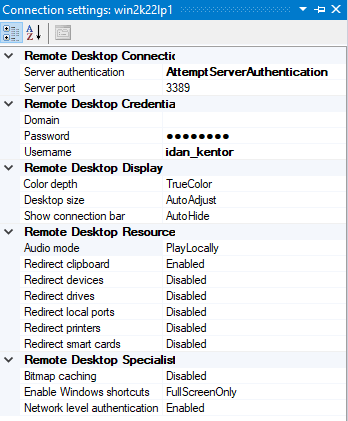
10. Connect to the Launch Pad VM.
Without further ado, let’s navigate to the PowerProtect Data Manager UI and register our GKE cluster as a Kubernetes Asset Source.
11. Navigate to Infrastructure -> Asset Sources.
12. Enable the Kubernetes Asset Source as needed and navigate to the Kubernetes tab.
13. Add the GKE cluster as a Kubernetes Asset Source:
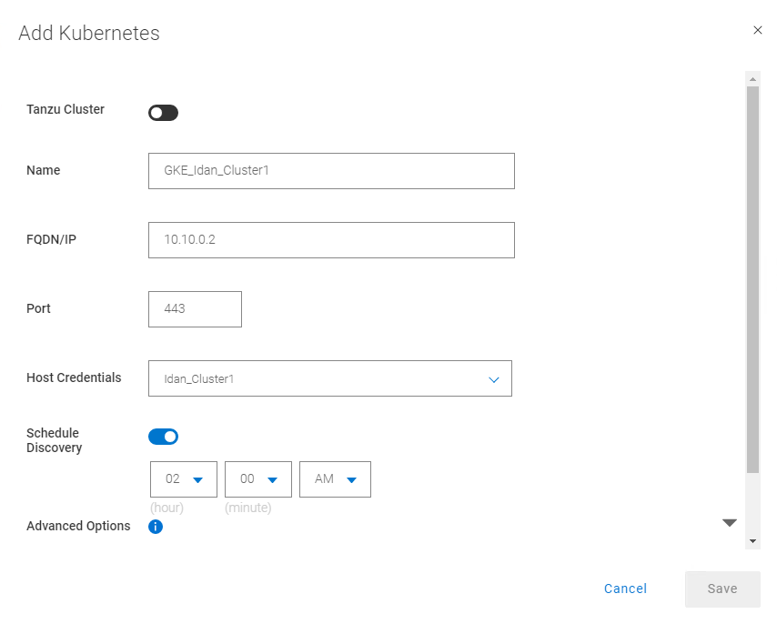
Some guidelines for adding GKE as an asset source:
14. For FQDN/IP, use the endpoint retrieved in Step 1 – make sure to remove the https:// prefix or use the IP that we retrieved in Step 2.
15. Specify port 443. Make sure to allow tcp/443 in the firewall for GKE (ingress) and for PPDM (egress). Also, allow tcp/111, tcp/2049, and tcp/2052 from GKE to PowerProtect DD.
16. Create new credentials with the Service Account Token from Step 3e.
17. Specify the Root Certificate:
a. On PPDM versions earlier than 19.12, follow these steps:
-- Convert the GKE root CA to BASE64 using the following command:
gcloud container clusters describe <your-gke-cluster-name> --zone <your-zone> | grep -i clustercacert | awk '{print $2}' | base64 -d-- SSH to the PPDM server using the admin user and save the root CA in BASE64 to a file, say gke-cert.txt. Make sure to include the BEGIN and END CERTIFICATE lines.
-- Execute the following command:
ppdmtool -importcert -alias <your-gke-cluster-name> -file gke-cert.txt -t BASE64
b. On PPDM 19.12 and later, select Advanced Options in the same Add Kubernetes screen and scroll down. Specify the root certificate that we retrieved in Step 4.
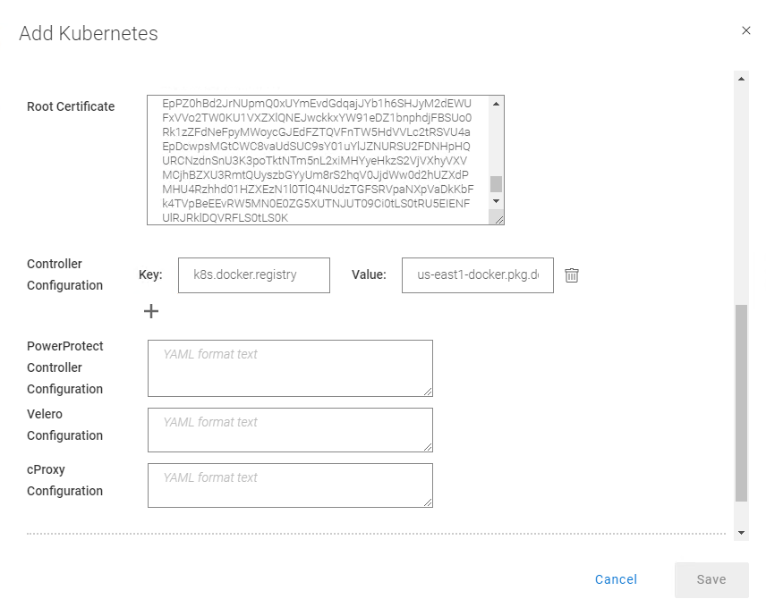
18. Under Controller Configuration, add the following to use the container images from the registry that we configured in Step 18 in the section “PowerProtect K8s container images”).
Key: k8s.docker.registry
Value: us-east1-docker.pkg.dev/gcp-dev-idan-pte/ppdm
Make sure to change the value to match your repository address.
With PPDM 19.10, this setting can be applied using REST API, specifically POST /api/v2/inventory-sources on an existing K8s asset source. To do this, follow the instructions described in Updating PowerProtect Data Manager pod configurations on https://developer.dell.com.
19. Scroll down, verify the certificate, and click Save to register the GKE cluster as a Kubernetes Asset Source.
There you have it! Now you can deploy your stateful applications on your GKE cluster using kubectl or straight from the GCP marketplace and protect their namespaces by creating a new Protection Policy 👍🏻.
Feel free to reach out with any questions or comments.
Thanks for reading,
Idan
Author: Idan Kentor
idan.kentor@dell.com

PowerProtect Data Manager – How to Protect AWS EKS (Elastic Kubernetes Service) Workloads?
Thu, 17 Nov 2022 18:03:30 -0000
|Read Time: 0 minutes
PowerProtect Data Manager supports the protection of a multitude of K8s distributions for on-prem as well as in the cloud (see the compatibility matrix). In this blog, I’ll show how to use PowerProtect Data Manager (or PPDM for short) to protect AWS Elastic Kubernetes Service (EKS) workloads.
I’ve been asked many times recently if PPDM supports protection of Amazon EKS workloads, and if so, how the configuration goes. So, I thought it would be good to talk about that in a blog -- so here we are! In essence, the challenging piece (no issues, maybe challenges 😊) is the configuration of the EBS CSI driver, so I’ll cover that extensively in this blog. And because the deployment and configuration of the EBS CSI driver has changed recently, there is all the more reason to get this information out to you.
Deploying PowerProtect Data Manager and PowerProtect DD are both pretty straightforward. You just need to launch the PowerProtect Data Manager installation from the marketplace, answer some network and other questions, and off you go. It creates an AWS CloudFormation stack that deploys all the required services of both PowerProtect Data Manager and PowerProtect DD. PowerProtect DD can be deployed separately or along with PPDM. Naturally, the newly deployed PowerProtect Data Manager can also leverage an existing PowerProtect DD.
Deploying and configuring the EKS cluster and Node groups is rather simple and can be done using the AWS management console, AWS CLI, or eksctl. For more information, the official Amazon EKS documentation is your friend.
It’s important to talk about the tools we need installed for managing Amazon EKS and to deploy and manage the EBS CSI driver:
- kubectl – Probably needs no introduction but it’s a command line tool to work with Kubernetes clusters.
- AWS CLI – A command line tool for working with AWS services. For installation instructions and further info, see Installing or updating the latest version of the AWS CLI.
- eksctl – A command line tool to create and manage EKS clusters. For more info, see Installing or updating eksctl.
Let’s look at some general steps before we go ahead and deploy the EBS CSI driver.
To get started
1. To configure AWS CLI, run the following command:
aws configure
2. List your EKS clusters:
aws eks --region <region-code> list-clusters
3. Configure kubectl to operate against your EKS cluster:
aws eks update-kubeconfig --name <your-eks-cluster-name>
Deploying the External Snapshotter
The final step before we can deploy the EBS CSI driver is to deploy the external snapshotter.
1. To deploy the snapshotter, execute the following commands:
kubectl apply -f https://raw.githubusercontent.com/kubernetes-csi/external-snapshotter/master/client/config/crd/snapshot.storage.k8s.io_volumesnapshotclasses.yaml
kubectl apply -f https://raw.githubusercontent.com/kubernetes-csi/external-snapshotter/master/client/config/crd/snapshot.storage.k8s.io_volumesnapshotcontents.yaml
kubectl apply -f https://raw.githubusercontent.com/kubernetes-csi/external-snapshotter/master/client/config/crd/snapshot.storage.k8s.io_volumesnapshots.yaml
kubectl apply -f https://raw.githubusercontent.com/kubernetes-csi/external-snapshotter/master/deploy/kubernetes/snapshot-controller/rbac-snapshot-controller.yaml
kubectl apply -f https://raw.githubusercontent.com/kubernetes-csi/external-snapshotter/master/deploy/kubernetes/snapshot-controller/setup-snapshot-controller.yaml
2. Make sure the snapshot controller pods are running:
kubectl get pods -n kube-system
EBS CSI Driver Deployment
And now for the main event, the configuration of the EBS CSI driver. There are two ways to go about it – deploying the EKS CSI Driver as an EKS add-on or as a self-managed driver. You can use either the AWS management console or AWS CLI (eksctl) to deploy the EBS CSI Driver add-on. The self-managed driver is installed and operated exclusively using kubectl.
The following procedure represents my thoughts and experience for a quick and comprehensive configuration - there are few ways to climb a mountain as they say. Refer to the documentation for all possible ways.
Option 1: Self-managed EBS CSI Driver
1. Create or use an existing IAM user and map the required policy for the EBS CSI Driver to the user:
a. Create an IAM user:
aws iam create-user --user-name <user-name>
b. Create an IAM policy and record the Policy ARN:
aws iam create-policy --policy-name <policy-name> --policy-document https://raw.githubusercontent.com/
kubernetes-sigs/aws-ebs-csi-driver/master/docs/example-iam-policy.json
c. Attach the policy to the user:
aws iam attach-user-policy --user-name <user-name> --policy-arn <policy-arn>
d. Create an access key and record the AccessKeyId and SecretAccessKey:
aws iam create-access-key --user-name <user-name>
2. Create a secret. Here we’re creating a secret and mapping it to an existing IAM user and its credentials (for example, the access keys recorded in the previous step):
kubectl create secret generic aws-secret --namespace kube-system --from-literal "key_id=<iam-user-access-key-id>" --from-literal "access_key=<iam-user-secret-access-key>"
3. Install the EBS CSI Driver:
kubectl apply -k "github.com/kubernetes-sigs/aws-ebs-csi-driver/deploy/kubernetes/overlays/stable/?ref=release-1.12"
4. Make sure that the ebs-csi-controller and ebs-csi-nodes pods are running:
kubectl get pods -n kube-system
Option 2: EBS CSI Driver Add-on
1. Retrieve the EKS cluster OIDC provider:
aws eks describe-cluster --name <your-eks-cluster-name> --query "cluster.identity.oidc.issuer" --output text
2. Check if the OIDC provider of your cluster is not on the list of current IAM providers:
aws iam list-open-id-connect-providers
3. If the provider is not on the list, associate it by running the following command:
eksctl utils associate-iam-oidc-provider --cluster <your-eks-cluster-name> --approve
4. Create the IAM role. This would also attach the required policy and annotate the EBS CSI driver Service Account on the EKS cluster:
eksctl create iamserviceaccount --name ebs-csi-controller-sa --namespace kube-system --cluster <your-eks-cluster-name> --attach-policy-arn arn:aws:iam::aws:policy/service-role/AmazonEBSCSIDriverPolicy --approve --role-only --role-name <role-name>
5. Make sure that the aws-ebs-csi-driver is not installed:
aws eks list-addons --cluster-name <your-eks-cluster-name>
6. Get the AWS Account ID:
aws sts get-caller-identity --query "Account" --output text
7. Deploy the EBS CSI Driver add-on. Note that it will deploy the default add-on version for your K8s version. Specify the AWS account ID retrieved in the previous step and the IAM role specified in Step 4.
eksctl create addon --name aws-ebs-csi-driver --cluster <your-eks-cluster-name> --service-account-role-arn arn:aws:iam::<your-aws-account-id>:role/<role-name> --force
8. Make sure that the ebs-csi-controller and ebs-csi-nodes pods are running:
kubectl get pods -n kube-system
Storage Class Configuration
1. Create the Volume Snapshot Class YAML file:
cat <<EOF | tee snapclass.yaml
apiVersion: snapshot.storage.k8s.io/v1
kind: VolumeSnapshotClass
metadata:
   name: csi-aws-vsc
driver: ebs.csi.aws.com
deletionPolicy: Delete
EOF
2. Create the Snapshot Class:
kubectl apply -f snapclass.yaml
3. Make sure that the Snapshot Class got created:
kubectl get volumesnapshotclass
4. Create the Storage Class YAML file:
cat <<EOF | tee ebs-sc.yaml
apiVersion: storage.k8s.io/v1
kind: StorageClass
metadata:
   name: ebs-sc
   annotations:
     storageclass.kubernetes.io/is-default-class: "true"
provisioner: ebs.csi.aws.com
volumeBindingMode: WaitForFirstConsumer
EOF
5. Create the Storage Class:
kubectl apply -f ebs-sc.yaml
6. Patch the gp2 storage class to remove the default setting:
kubectl patch storageclass gp2 -p "{\"metadata\": {\"annotations\":{\"storageclass.kubernetes.io/is-default-class\":\"false\"}}}"7. Make sure that the EBS Storage Class got created and that it shows up as the default storage classone:
kubectl get storageclass
Add EKS to PowerProtect Data Manager
Now, for the grand finale – adding our EKS cluster to PPDM. Follow these steps to gather some information and then register EKS to PPDM.
1. Get the K8s cluster control-plane endpoint:
kubectl cluster-info
2. To create a service account on the EKS cluster for PPDM discovery and operations, PPDM RBAC YAML files need to be applied.
a. Retrieve the rbac.tar.gz file from the PPDM appliance at the following location:
/usr/local/brs/lib/cndm/misc/rbac.tar.gz
b. On PPDM 19.12, you can download the archive from the PowerProtect Data Manager UI under System Settings -> Downloads > Kubernetes, or directly using the following URL:
https://<your-ppdm-server>/k8s-binaries-download?filename=/usr/local/brs/lib/cndm/misc/rbac.tar.gz
Note that the link will only work if you’re logged into the PPDM UI. You can also find the archive on PPDM itself, at the following path:
/usr/local/brs/lib/cndm/misc/rbac.tar.gz
c. Extract the archive, navigate to the rbac directory, and apply the two YAML files using the following commands:
kubectl apply -f ppdm-discovery.yaml
kubectl apply -f ppdm-controller-rbac.yaml
d. If you’re using K8s 1.24 or later, then you must manually create the secret for the PPDM discovery storage account:
kubectl apply -f - <<EOF
apiVersion: v1
kind: Secret
type: kubernetes.io/service-account-token
metadata:
   name: ppdm-discovery-serviceaccount-token
   namespace: powerprotect
   annotations:
     kubernetes.io/service-account.name: "ppdm-discovery-serviceaccount"
EOF
e. Retrieve the secret key using the following command:
kubectl describe secret $(kubectl get secret -n powerprotect | awk '/disco/{print $1}') -n powerprotect | awk '/token:/{print $2}'3. Retrieve the EKS cluster root CA:
eksctl get cluster <your-eks-cluster-name> -o yaml | awk '/Cert/{getline; print $2}'Without further ado, let’s navigate to the PowerProtect Data Manager UI and register our EKS cluster as a Kubernetes Asset Source.
4. Navigate to Infrastructure -> Asset Sources.
5. Enable the Kubernetes Asset Source as needed and navigate to the Kubernetes tab.
6. Add the EKS cluster as a Kubernetes Asset Source:
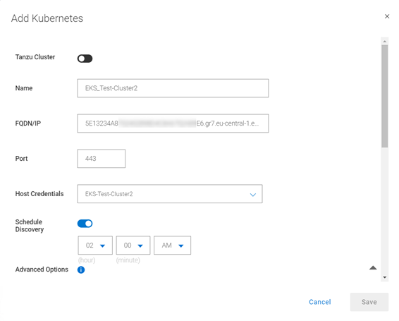
A few other notes:
7. Use the FDQN you retrieved in Step 1. Make sure to remove the https:// prefix.
8. Specify port 443. Make sure to add tcp/443 to the EKS security group (inbound) and the PPDM security group (outbound).
9. Create new credentials with the Service Account Token from Step 2e.
10. Root Certificate:
a. On PPDM versions earlier than 19.12, follow these steps:
- Convert the EKS root CA to BASE64 using the following command:
eksctl get cluster <your-eks-clsuter-name> -o yaml | awk '/Cert/{getline; print $2}' | base64 -d- SSH to the PPDM server using the admin user and save the root CA in BASE64 to a file, say eks-cert.txt. Make sure to include the BEGIN and END CERTIFICATE lines.
- Execute the following command:
ppdmtool -importcert -alias <your-eks-cluster-name> -file eks-cert.txt -t BASE64
b. On PPDM 19.12 and later, click Advanced Options on the same Add Kubernetes screen and scroll down. Specify the root certificate from Step 3.
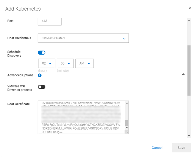
11. Verify the certificate and click Save to register the EKS cluster as a Kubernetes Asset Source.
That’s it, now you can deploy your stateful applications on your EKS cluster and protect their namespaces by creating a new Protection Policy 👍🏻.
Feel free to reach out with any questions or comments.
Thanks for reading,
Idan
Author: Idan Kentor
idan.kentor@dell.com

Data Protection for Virtualized Environments: Made Simpler with PowerProtect Data Manager
Thu, 11 Aug 2022 13:55:33 -0000
|Read Time: 0 minutes
VMware is arguably the leader in enterprise virtualization today. Used by countless enterprises to host their business-critical workloads, it has great features and capabilities across the board when it comes to manageability, scalability, and high-availability.
While VMware vSphere features great high-availability capabilities to your customers and business stakeholders, you still must protect your data from disaster. At the heart of any good disaster recovery plan is effective backups. When it comes to protecting virtual machines, there are best practices you want to follow when backing up your data.
For most businesses, when it comes to virtual machines (VMs), any kind of software or hardware failure typically results in some degree of financial loss when there are service interruptions. Actions such as granular restoration and full disaster recovery can also be especially useful in specific use cases. And you can perform all of these data recovery techniques (and more) with a proper VMware virtual machine backup solution.
PowerProtect Data Manager for a simpler way to back up virtualized environments
Dell PowerProtect Data Manager provides software-defined data protection, automated discovery, deduplication, operational agility, self-service, and IT governance for physical, virtual, and cloud environments.
- Orchestrate protection directly through an intuitive interface or empower data owners to perform self-service backup and restore operations from their native applications
- Ensure compliance and meet even the strictest of service level objectives
- Leverage existing Dell PowerProtect appliances
PowerProtect Data Manager provides a consistent protection experience for VMware environments. Data Manager is the only solution to provide native vSphere integration with vCenter for VM protection, allowing storage and backup admins, as well as VM owners, to choose a storage policy to apply to each VM automatically when it is instantiated.
PowerProtect Data Manager integration with VMs helps to manage, protect, and reuse VM data across the enterprise by deploying services to accomplish the following tasks:
- Discover, access, and recover VM copies non-disruptively across primary and protection storage without introducing new infrastructure or complexity
- Automate efficient copy creation
- Efficiently automate data retention SLA compliance, ensuring that the right number of copies are stored in the right place at the right level of protection
- Optimize operations based on actionable analytics and insight
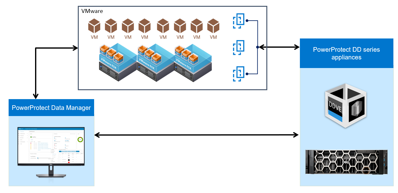
Virtual Machine (VM) backup options
- VM Consistent Backup:
Capture all the virtual machine disks at the same time and back up the data to storage targets to create a transactional-consistent backup. This option for can be used for Windows and Linux VMs, and for guest operating systems that have applications other than the SQL Server.
- Application-Aware Backup:
Application aware full backup is an extension of VM full backup. For VMs with a SQL application installed, select this type to quiesce the application to perform the SQL database and transaction log backup. When you select this type, you must provide Windows account credentials for the VM.
VM Direct Engine is the protection appliance within PowerProtect Data Manager that allows you to manage and protect VM assets. The PowerProtect Data Manager software comes pre-bundled with an embedded VM Direct engine and allows you to deploy additional external VM Direct Engines.
VM Direct protection engine
VM Direct Engine is deployed in the vSphere environment to perform virtual machine snapshot backups. VM Direct Engine improves performance and reduces network bandwidth utilization by using PowerProtect DD series appliance source-side deduplication.
Basically, there are two types of VM Direct Engines: Internal and External.
Internal VM Direct Protection Engine:
- Protection using Transparent Snapshot Data Mover (TSDM)
- For small scale environments
- Does not require concurrent backups
- Uses Network Block Device transport mode
- Data is transferred over the network to the ESXi server that is hosting the proxy
- Proxy gets data from its ESXi host and writes to storage
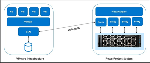
External VM Direct Protection Engine
- For larger scale environments
- Requires concurrent data protection operations
- Can also use NBD but the preferred method is to use Hot-Add transport mode for better performance
- Proxy attaches itself to VM disk snapshots to be backed-up
- Proxy reads data from the attached disk and writes to storage
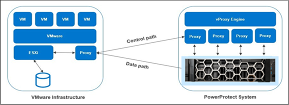
Note: When you deploy and register an additional VM Direct Engine, PowerProtect Data Manager uses this appliance instead of the embedded VM Direct Engine. If the added VM Direct Engine is not available, the embedded VM Direct Engine is used to ensure that backups complete successfully.
Depending on the vSphere version and the VM protection policy options selected, VM Direct can protect VMs by using traditional VMware APIs for Data Protection (VADP) snapshots, or by using the Transparent Snapshot Data Mover (TSDM) protection mechanism introduced in PowerProtect Data Manager version 19.9.
An external VM Direct Engine is not required for VM protection policies that use the Transparent Snapshot Data Mover (TSDM) protection mechanism. For these policies, the embedded VM Direct Engine is sufficient.
vStorage API for Data Protection (VADP) snapshots
PowerProtect Data Manager supports Change Block Tracking (CBT), which allows backup applications to determine the delta of changes in the VM since the last backup, and only read and transfer those changes when doing the next backup incrementally. This allows PowerProtect Data Manager to use one or more VM proxies to read a VM's disk changes and to transfer them.
Any L0 backup of a VM reads the entire contents of all disks and writes the same to storage using DD Boost (leveraging global deduplication). Any non-L0 backup of a CBT enabled VM will only read changes in the disks from the last backup and overlay those changes on a copy of the last backup to generate a new full backup (while moving only incremental changes).
Backup files are written to storage using fixed size segments (FSS) of 8K. Backup files on storage are always thick, that is, VMDK file-size on storage is equal to the size of the provisioned disk.
Transparent Snapshot Data Mover (TSDM)
TSDM is a protection mechanism in PowerProtect Data Manager and was designed to replace the VMware vStorage API for Data Protection (VADP) protection mechanism for crash-consistent VM protection.
The advantages of using the TSDM protection mechanism for VM data protection include the following:
- Eliminates the latency and performance impact on the production virtual machine during the protection policy life cycle
- Reduces the CPU, storage, and memory consumption required for backups. After the initial full backup, only incremental backups using the immediate previous snapshot are performed.
- An external VM Direct engine is not required. The VM Direct engine embedded with PowerProtect Data Manager is sufficient.
- Automatic scaling
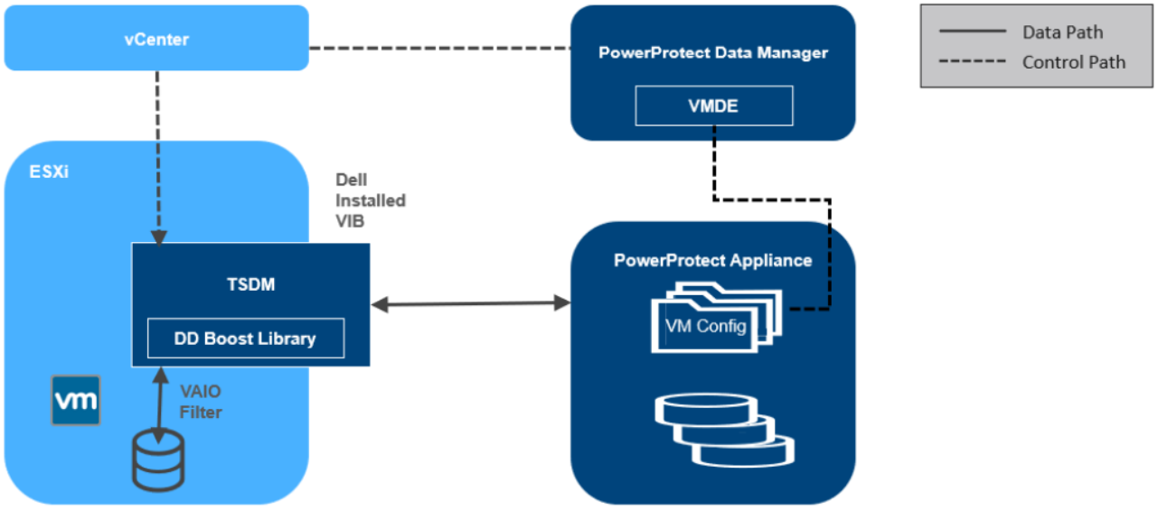
Transparent snapshots architecture
For more details, see the technical white paper VMware Virtual Machine Protection using Transparent Snapshots.
Note: PowerProtect Data Manager manages the TSDM component by using the VIB (VMware Certified) from Dell Technologies. This component is installed dynamically as part of the integration of PowerProtect Data Manager that requires protection of VMs using Transparent Snapshots. The APIs being used are supported in VMware ESXi 7.0 U3 and later.
Transport modes used in PowerProtect Data Manager
PowerProtect Data Manager supports the HotAdd and Network Block Device (NBD) transport modes. You select a transport mode when adding the vProxy appliance (Hot-Add, NBD, or the default settings Hot Add, Failback to Network Block Device).
In NBD mode, the ESX/ESXi host reads data from storage and sends it across a network to the target storage. As its name implies, this transport mode is not LAN‐free, unlike SAN transport.
HotAdd is a VMware feature in which devices can be added “hot” while a VM is running. Besides SCSI disk, VMs can add additional CPUs and memory capacity. If backup software runs in a virtual appliance, it can take a snapshot and create a linked clone of the target virtual machine, then attach and read the linked clone’s virtual disks for backup. This involves a SCSI HotAdd on the ESXi host where the target VM and backup proxy are running. Virtual disks of the linked clone are Hot Added to the backup proxy. The target VM continues to run during backup.
PowerProtect plug-in for the vSphere Client
If you want to make a subset of the PowerProtect Data Manager UI functionality available within the vSphere Client, select vSphere Plugin. When adding a vCenter server as an asset source in the PowerProtect Data Manager UI, if you enable the vSphere Plugin option, a pane for PowerProtect appears in the vSphere Client.
This pane provides a subset of PowerProtect Data Manager functionality, including the option to perform a manual backup, image-level restore, and a file-level restore of PowerProtect Data Manager VM protection policies.
PowerProtect Search Engine
PowerProtect Search Engine is installed by default when PowerProtect Data Manager is installed. The PowerProtect Search Engine indexes virtual machine file metadata to enable searches based on configurable parameters. When the indexing is added to protection policies, the assets are indexed as they are being backed up.
You can add up to five search nodes starting from PowerProtect Data Manager v19.5. You can index up to 1000 assets (VMs) per node.
Supported use cases:
- Searching for files from their respective copies across VMs of different kinds (Windows and Linux)
- Searching for files from their respective backup copies for similar kinds of VMs
- Searching for files and trying to restore the file from its various backup copies at different Points-In Time (PITs)
Supported enhanced VMware topologies for VM protection
PowerProtect Data Manager provides protection for clustered ESXi server storage, networking, and enterprise management. Understanding which topologies are supported in these environments can help you design your network infrastructure.
Supported enhanced topologies
Supported topologies of clustered ESXi server storage, networking, and enterprise management include the following:
- vSAN operations
- NSX-T port groups
- Enhanced Link Mode vCenter servers
After virtual assets are backed up as part of a virtual machine protection policy in the PowerProtect Data Manager UI, you can perform image-level and file-level recoveries from individual or multiple VM backups, and restore individual virtual machine disks (VMDKs) to their original location.
Virtual Machine Restore Options
After virtual assets are backed up as part of a virtual machine protection policy in the PowerProtect Data Manager UI, users can perform image-level and file-level recoveries from individual or multiple virtual machine backups, and also restore individual virtual machine disks (VMDKs) to their original location. Below are the different types of recoveries that can be performed, according to customer requirements.
- Restore to a new virtual machine — A Create and Restore to New VM enables you to create a new VM using a copy of the original VM backup. Other than having a new name or location and a new vSphere VM Instance UUID, this copy is an exact replica of the VM that you backed up with the protection policy in PowerProtect Data Manager.
Note: Full SQL-database and transaction log restores of a virtual machine from application aware virtual machine protection policies must be performed using Microsoft application agent tools.
- Restore individual virtual disks — A Restore Individual Virtual Disks operation recovers individual virtual disks (VMDKs) to their original location on the vCenter server, rolling the VMDKs that you backed up with the protection policy in PowerProtect Data Manager to an earlier point in time.
- Restore to the original virtual machine — A Restore to Original VM operation recovers a VM backup to its original location on the vCenter server. This operation rolls the VMs that you backed up with the protection policy in PowerProtect Data Manager to an earlier point in time.
Note: Starting with PowerProtect Data Manager version 19.10, you can restore the VM configuration during a Restore to Original VM. If there were changes to the VM disk configuration, you cannot clear this option.
- Self-service restores — A PowerProtect Data Manager system or security administrator can enable users to perform self-service restores of their own assets without further administrator intervention. Self-service restores require a scope of authority that includes the Restore Administrator role for the relevant user assets or asset sources.
- Direct restore to ESXi — If the VM you protected with PowerProtect Data Manager was a vCenter VM, but the VM and vCenter server are now lost or no longer available, direct restore to ESXi enables you to recover the VM directly to an ESXi host without a vCenter server.
Note: Direct Restore to ESXi restore requires either the embedded VM Direct Engine with PowerProtect Data Manager, or an external VM Direct appliance that is added and registered to PowerProtect Data Manager. Additionally, ensure that you disconnect the ESXi host from the vCenter server.
- Instant Access VM restore — An Instant Access VM restore enables you to create a new VM directly from the original VM backup on protection storage for instant backup validation and recovery of individual files. The instant access VM is initially available for seven days. This process does not copy or move any data from protection storage to the production datastore. An instant access VM restore also provides the option to move the VM to a production datastore when you want to retain access to the VM for a longer time.
Data and workloads have evolved over time, leading to a multi-generational data sprawl that introduces multiple risks to your business. Collectively, this set of risks form a business integrity gap: the gap between where organizations’ data environments are today, hampered by the challenges of data sprawl, and where their data environments should be in-order to thrive, accelerate, and digitally transform.
PowerProtect Data Manager helps you meet these challenges with its Intelligent Data Services Platform, closing the business integrity gap and enabling organizations to accelerate business growth. With its Intelligent Data Services Platform, PowerProtect Data Manager delivers a flexible, future-proof architecture.
PowerProtect Data Manager provides a single, robust VMware backup solution. Why settle for multiple point solutions for backup and recovery, disaster recovery and test/development when you can deploy PowerProtect Data Manager to provide these capabilities in a single solution?
For more details on PowerProtect Data Manager Virtualized Environment protection, see the white paper Dell PowerProtect Data Manager: Virtual Machine Protection and visit the Dell PowerProtect Data Manager web site.
Author: Chetan Padhy, Senior Engineering Technologist, Data Protection Division

Multi-cloud Protection with PowerProtect Data Manager
Thu, 14 Apr 2022 20:12:59 -0000
|Read Time: 0 minutes
What I like most about PowerProtect Data Manager is that it supports the rising demand for data protection for all kind of organizations. It’s powerful, efficient, scalable and most importantly: a simple-to-use solution. And what could be simpler than using the same product with the same user interface on any environment, including any supported cloud platform?
PowerProtect Data Manager is usually used for deploying and protecting on-prem virtual machines running on VMware vSphere environments.
While PowerProtect Data Manager excels in protecting any on-prem machines and different types of technologies, such as Kubernetes, some organizations also have a cloud strategy where some or all their workloads and services are running on the cloud.
There are also organizations that use multiple cloud platforms to host and manage their workloads, and these resources need to be protected as well, especially in the cloud where there could be additional risk management and security considerations.
The good news is that PowerProtect Data Manager provides cloud and backup admins the same abilities and interface across all the supported cloud platforms: Amazon Web Services (AWS), Microsoft Azure, and Google Cloud Platform (GCP).
AWS users can use the AWS Marketplace to deploy “Dell EMC PowerProtect Data Manager and PowerProtect DD Virtual Edition” which will trigger an automated deployment using the AWS CloudFormation service.
In this deployment method you’re asked to provide all the networking and security details ahead, and then it does everything else for you, including deploying a DDVE instance that will manage the backup copies for you (with deduplication!).
Once the CloudFormation stack is deployed, you can access the PowerProtect Data Manager through any web browser, and then add and protect your cloud resources, just as if it were an on-prem deployment – super intuitive and super easy!!
I think the trickiest part in the deployment is probably to make sure that all of the networking and firewall or other security and policy restrictions allow you to connect to the PowerProtect Data Manager VM and to the DDVE.
Check out this great whitepaper that describes the entire process of deploying PowerProtect Data Manager on AWS.
For Microsoft Azure users, the process here is similar. You can deploy PowerProtect Data Manager using the Azure Marketplace service:
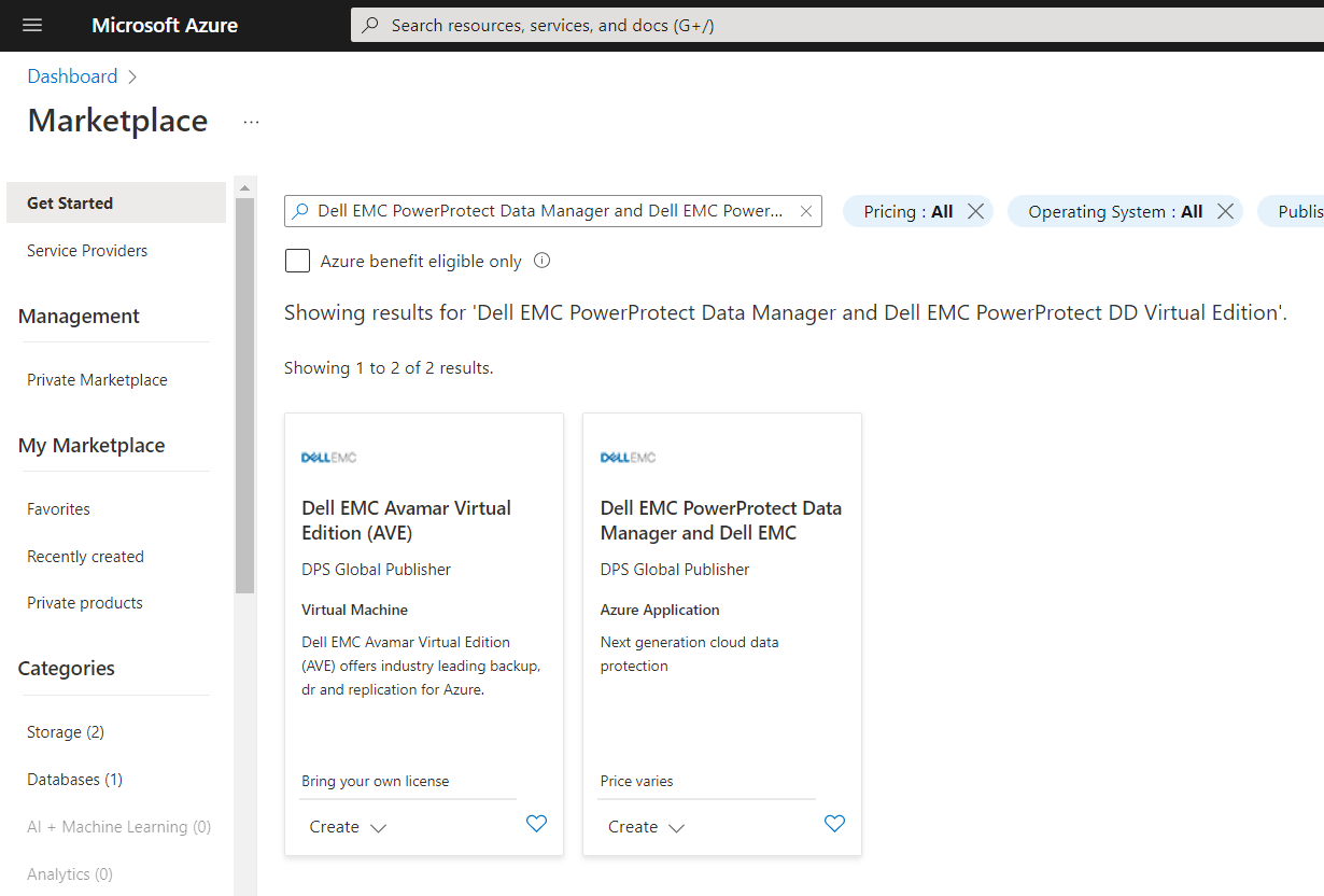
This whitepaper will take you through the exact steps required to successfully deploy PowerProtect Data Manager and PowerProtect DDVE on your Azure subscription.
Didn’t I say it’s really easy and works the same way in all the cloud platforms?
GCP users can use the GCP Marketplace to deploy their PowerProtect Data Manager:
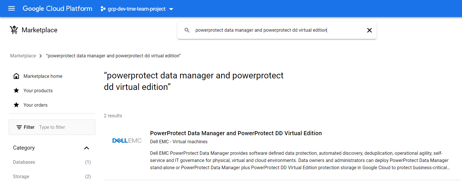
This whitepaper describes the entire deployment process with detailed screenshots on GCP.
Now you can easily protect your multi-cloud resources with the same powerful protection solution!
Author: Eli Persin

Conquer Your Challenges with Dell PowerProtect Data Manager Dynamic NAS Protection
Wed, 16 Feb 2022 21:53:54 -0000
|Read Time: 0 minutes
Challenges when protecting NAS
For years, NAS and backup vendors have used Network Data Management Protocol (NDMP) to protect NAS data. But NDMP has its own limitations, such as manual slicing of a NAS share to achieve multi-stream backup, limited parallel streams, and requires periodic full backups. Customers also face challenges to protect their growing amounts of data and to back up that data within their specified backup windows. With NDMP, full image restores are required for a file-level recovery and restore to any NAS device, such as NFS/CIFS, are not supported. These challenges lead to missed data protection and Service Level Agreements (SLAs).
PowerProtect Data Manager Dynamic NAS protection
Dell PowerProtect Data Manager for NAS protection addresses today’s customer challenges of protecting evolving NAS environments. In the PowerProtect Data Manager 19.9 software release, we introduced a new NAS data protection solution called Dynamic NAS protection. Unlike NDMP-based solutions, Dynamic NAS protection is a NAS-vendor-agnostic solution. With Dynamic NAS protection, customers can overcome some of the challenges they faced with NDMP.
Dynamic NAS protection addresses the challenges with the following capabilities:
- Vendor-agnostic solution for NAS protection
- Forever incremental backup
- High number of parallel streams and multiple virtual containers to address scale and performance
- Index, search, and restore
- Restore to any NAS device, such as NFS/CIFS
Dynamic NAS protection provides a non-NDMP, crawl- and backup-based solution by leveraging the NAS Protection Engine internally using Filesystem Agents (FSA) file based-backup (FBB) technology.
Dynamic NAS protection uses the NAS Protection Engine for backup and recovery orchestration. This solution is easy to use, providing automatic discovery, orchestration, and management through the Data Manager UI.
Data Manager for NAS protection solution supports all the Data Manager objectives such as DD Replication, Cloud Tier, progress monitoring, and SLA compliance.
Dynamic NAS protection - Intelligent auto slicer
The NAS file share auto slicer is a new library that is embedded in the Data Manager NAS agent. The slicer splits NAS assets (NAS share, a file system) into multiple sub-assets in preparation for multi-stream data movement to a Dell PowerProtect DD series appliance. Slices are created using parallel threads, and each slice is backed up concurrently using available NAS Protection Engine containers and moved to a PowerProtect DD series appliance.
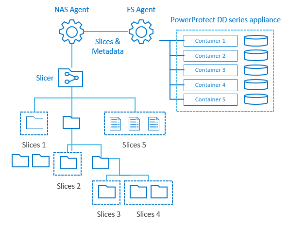
The slicer partitions NAS assets dynamically before each backup. Based on backup history and changes in the content of the NAS asset being sliced, relevant slices are added, removed, or rebalanced. Periodically, unbalanced trees are automatically managed as content changes over time. No manual reconfiguration is required. The default slice size is 200 GB or 1 million files.
For a full backup, a complete share is traversed in parallel to create slices. For an Incremental backup, only modified slices are traversed based on backup history.
Auto distribution of backup streams
Dynamic NAS protection enables automated load balancing of protection engine hosts, and automatic scaling for containers to achieve maximum backup streams and reduce manual management overhead. The NAS protection containers spin up and tear down, depending upon the workload. Each NAS Protection Engine can run multiple containers. Each container is pre-installed with a NAS agent and an FSA agent.
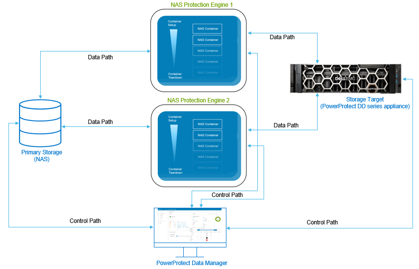
Protecting NAS assets with Data Manager
With the Data Manager 19.9 software release, the Dynamic NAS solution supports protection for Dell PowerStore, Dell Unity, and Dell PowerScale (Isilon) NAS products, and any NFS or CIFS share using generic NAS for vendors such as NetApp, Windows, and Linux file servers.
Data Manager can protect NAS assets in two ways:
- Appliances: Automatic discovery of shares on supported Dell PowerStore, Dell Unity, and Dell PowerScale (Isilon) products.
- Shares: Network File System (NFS) and Common Internet File System (CIFS) shares from other NAS platforms.
Restoring the NAS assets with Data Manager
Data Manager provides support to restore a NAS asset to the original location or to an alternate location. Data Manager also supports FLR using the search engine to restore individual files and folders from NAS backups. Once the Search Engine is deployed and NAS protection policy is enabled with indexing, individual files and folders can be restored from one or more NAS backups by using the File Search option.
Data Manager for NAS protection supports the following restore use cases:
- Share-level restore
- Restore to any device, NFS or CIFS
- Restore to original and alternate NAS shares
- File-Level Recovery (FLR): NAS backups are indexed on the Search Engine for search and restore operations.
With many enhancements across our Dell data protection software offerings, Dell Technologies continues to drive innovation without compromise. We stop at nothing to give you technology innovations that modernize the protection of your NAS infrastructure.
Easily automate and optimize with Dynamic NAS protection available with Data Manager. With its snapshot technology and intelligent slicing, Data Manager protects NAS data efficiently within the required backup window. Dynamic NAS protection offers up to 3x faster backups[1] and up to 2x faster restores[2].
For more details on Data Manager Dynamic NAS protection, see the white paper Dell PowerProtect Data Manager: Dynamic NAS Protection and visit the Dell PowerProtect Data Manager web site.
Author: Vinod Kumar Kumaresan, Senior Engineering Technologist, Data Protection Division
[1] When comparing PowerProtect Data Manager 19.9 with Dynamic NAS protection backup performance to NDMP backup performance with Avamar. Based on Dell internal testing. August 2021.
[2] When comparing PowerProtect Data Manager 19.9 with Dynamic NAS protection restore performance to NDMP restore performance with Avamar. Based on Dell internal testing. August 2021.

OpenShift Covered Under the Shield of Dell PowerProtect Data Manager
Wed, 09 Feb 2022 19:59:36 -0000
|Read Time: 0 minutes
About a decade ago, no one thought there could be hassle free deployment and management of applications without worrying about the OS and infrastructure. When I first started using containerization, I was a little surprised and relaxed because I didn’t need to worry about whether my code/application would run on a different platform/machine or not.
Container technologies are widely being accepted and used owing to application modernization and DevOps. Kubernetes is an open-source container management platform that unifies a cluster of machines into a single pool of compute resources. OpenShift is a PaaS platform that is built on top of Kubernetes and automates the development to deployment workflow for an application.
There has also been a continued emphasis on distributed data intensive applications that leverage both traditional relational (SQL) and non-relational (NoSQL) databases for data persistence. Databases deployed on OpenShift can be used in conjunction with both Container Storage Interface (CSI) and VMware Cloud Native Storage variants. With containers deployed in distributed environments, it becomes more important to protect these workloads and to ensure availability in case of a disaster recovery situation. Here comes Dell PowerProtect Data Manager to the rescue.
PowerProtect Data Manager! Saving the day!
PowerProtect Data Manager ensures that data is easy to back up and restore, and remains available, consistent, and durable in a Kubernetes workload. PowerProtect DD Series appliances are the preferred target for PowerProtect Data Manager, which brings the benefit of deduplication, performance, efficiency, and security. PowerProtect Data Manager provides a centralized management UI where protection policies can be defined to manage clusters, namespaces, and other OpenShift components.
Protecting OpenShift workloads with PowerProtect Data Manager
OpenShift adds several additional components on top of standard Kubernetes meta data components including Build, BuildConfig, ImageStream, ImageStreamTag, DeploymentConfig. These additional components allow a supporting source-to-image and image-to-deployment workflow that takes an existing source code repository and converts an associated container to Docker images. These components are required to be protected when restoring OpenShift namespaces.
An OpenShift Kubernetes cluster can be registered with PowerProtect Data Manager by adding the details of the cluster in the PowerProtect Data Manager portal. Once you add the cluster, associated namespaces are available to be protected. Policies can be created to schedule and run the backup and you can also replicate and restore the protected assets.
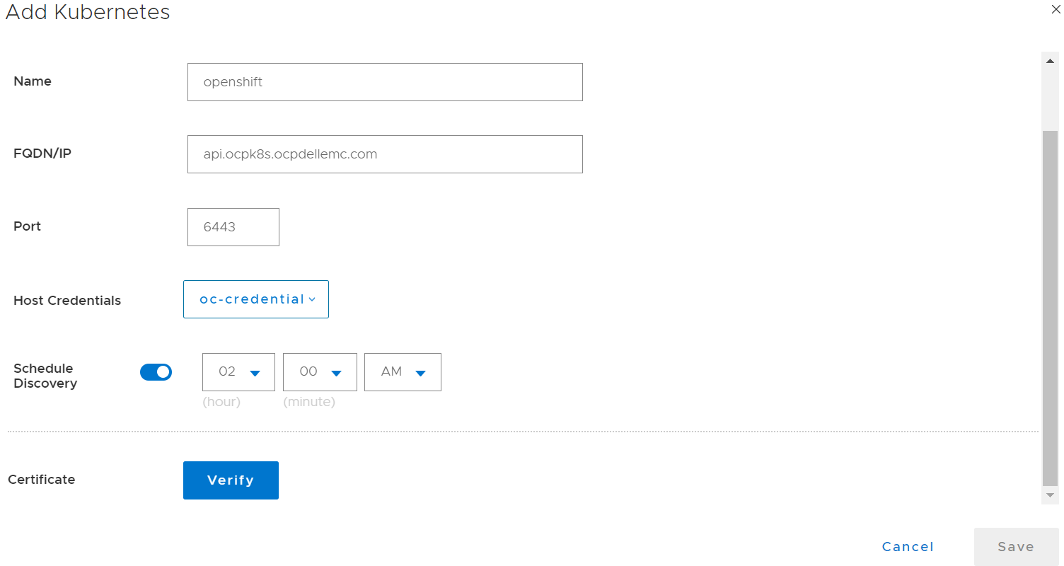
Figure 1. Adding OpenShift Kubernetes cluster as an asset source
The powerprotect and velero-ppdm namespaces are created automatically once the cluster is integrated with PowerProtect Data Manager. During the discovery process, when OpenShift cluster is detected in PowerProtect Data Manager, the OpenShift Application Data Protection (OADP) operator is automatically installed, which further deploys velero and required plugins. During backups and restores, the OpenShift plugin will be leveraged to back up the associated OpenShift components. This process is transparent to the user in terms of policy creation and during restores.

Figure 2. PowerProtect Data Manager Controller with OADP
PowerProtect Controller is the component that is installed on the Kubernetes cluster when PowerProtect Data Manager discovers the cluster. The backup and restore controllers manage BackupJob Custom Resource (CR) and RestoreJob CR definitions and are responsible for the backup and restore of Persistent Volumes.
The stateless containerized proxy (cProxy) gets installed on Kubernetes cluster when the backup and restore process initiates and gets deleted when those processes are completed. It is responsible for managing Persistent Volume snapshots (snap copies) and mounting snapshots and for moving the data to the target storage. It is also responsible for restoring data into Persistent Volumes from target storage and making the data available for attaching to Pods. It also acts as an agent plug-in orchestrator for application aware backups.
PowerProtect Data Manager can easily integrate with OpenShift Kubernetes cluster, ensuring that data on the cluster is easy to back up and restore, always available, consistent, and durable.
For more details on how to protect OpenShift Kubernetes cluster, see the white paper PowerProtect Data Manager Protecting OpenShift Workloads.
Author: Charu

Dell PowerProtect Hadoop Data Protection – a Modern and Cost-effective Solution for Big Data Apache Hadoop
Thu, 27 Jan 2022 19:10:36 -0000
|Read Time: 0 minutes
Big Data is no longer a buzzword. Over the past decade, big data and analytics have become the most reliable source of insight for businesses as they harness collective data to align strategy, help teams collaborate, uncover new opportunities, and compete in the global marketplace. The market size for business data analytics (BDA) was USD 206.95 billion in 2020 and USD 231.43 billion in 2021, according to Fortune Business Insights™ in its report, titled, “Big Data Analytics Market, 2021-2028”.
With big data analytics on the course to become the most mission critical enterprise application, enterprises are demanding a robust level of backup, recovery, and disaster recovery solutions for their big data environment, in particular Apache Hadoop®. Apache Hadoop is a clustered distributed system that is used to process massive amounts of data. It provides software and a framework for distributed storage and processing of big data, using various distributed processing models.
Some common mistakes that make data protection challenging in Apache Hadoop:
- Because Apache Hadoop has 3X replication by default, many administrators do not plan to back up the data again.
- A very common misconception is that Apache Hadoop is just a repository for data that resides in existing data warehouses or transactional systems, so the data can be reloaded.
- Data is unstructured and often huge in size and it takes a very long time for backups to complete.
- Administrators mistakenly believe that Apache Hadoop is missing built-in technologies such as replication and mirroring with Apache Falcon, distcp, HBase, and Hive Replication.
Why do we need a dedicated Data Protection solution in Apache Hadoop aside from replication and in-built snapshots?
- Apache Hadoop infrastructure with 3x replication is a costly solution and long-time retention is not possible for huge volumes of data, so we need a cost-effective solution that can save multiple copies of important data.
- Social media data, ML models, logs, third-party feeds, open APIs, IoT data, banking transactions, and other sources of data may not be reloadable, easily available, or in the enterprise at all. So, this is critical single-source data that must be backed up and stored forever for meeting internal or legal compliance requirements for RPO and RTO.
- Synchronously replicating data will negatively impact application performance. Synchronous replication will also intercept all writes to the file system. This can destabilize the production system and requires extensive testing prior to putting it into production.
- Some natural disaster that takes out an entire data center, an extended power outage that makes the Apache Hadoop platform unavailable, a DBA accidentally dropping an entire database, an application bug corrupting data stored on HDFS, or worse: a cyberattack such as ransomware.
Overview of Dell PowerProtect Hadoop Data Protection
Dell Technologies has developed a Hadoop File System driver for PowerProtect DD series appliances that allows Hadoop data management functions to transparently use DD series appliances for the efficient storage and retrieval of data. This driver is called DD Hadoop Compatible File System (DDHCFS).
DDHCFS is the Hadoop-compatible file system that is used by DD series appliances. It provides versioned backups and recoveries of the Hadoop Distributed File System (HDFS) by using DD snapshots. It provides source-level deduplication and direct backups to DD series appliances. DDHCFS can also distribute backup-and-restore streams across all HDFS DataNodes, making backups and restores faster. It can also be integrated with Kerberos and Hadoop local credentials.
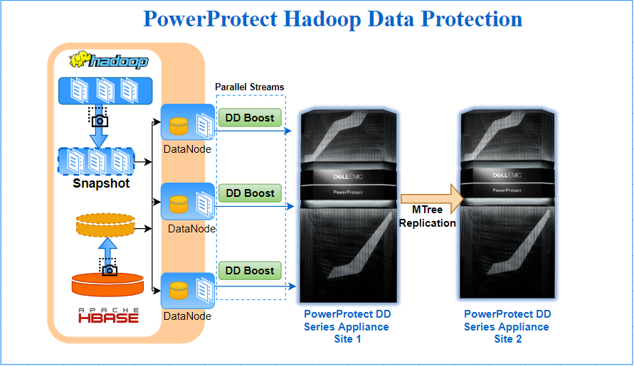
PowerProtect Hadoop Data Protection requires minimal configuration and installs only on the one node of the Hadoop Cluster. It is tightly integrated into the Hadoop file system, and leverages Hadoop’s scale-out distributed processing architecture to parallelize data transfer from Hadoop to the PowerProtect DD series appliance. DD Boost provides a network-efficient data transfer with client-side deduplication, while PowerProtect DD provides storage efficiency through deduplication and compression. Together this makes it the most efficient method of moving large amounts of data from a Hadoop cluster to a PowerProtect DD series appliance. Internally standard Hadoop constructs like Distributed File Copy & HDFS/HBase snapshots are leveraged to accomplish backup tasks.
Some highlights of the PowerProtect Hadoop Data protection solution for Hadoop environments are:
- True point-in-time backup and recovery of HDFS data to the PowerProtect DD series appliance
- Full backups at the low cost of incremental (synthetic full) – incremental forever
- Flexible Licensing (included in the PowerProtect and DP Suite license)
- Bandwidth efficiency of DD Boost sends only unique data over the network
- Capacity savings of up to 70% by means of global deduplication and compression on DD series appliances
- Source level deduplication and load balancing via DDBoost interface group
- HDFS integration transparently works through the three way storage redundancy to back up one consistent copy of the data
- Uses standard Hadoop constructs (such as MapReduce and distcp) to spawn distributed DD Boost agents to parallelize data transfer to PowerProtect DD series appliances
- Self-service, script-based backup, restores, and listing. Every Hadoop administrator can readily use these commands and incorporate them into other workflows
- Backup operations can be further scheduled and automated by Oozie
- Audit log of configuration changes and backup monitoring
Conclusion
PowerProtect Hadoop Data Protection, which is part of the Dell Data Protection Suite Family, provides complete Hadoop data protection. Apache Hadoop customers further benefit from PowerProtect DD series appliances when using the power of DD Boost, with strong backup performance, reduced bandwidth requirements, and improved load balancing and reliability.
The PowerProtect DD series appliances’s Data Invulnerability Architecture provides outstanding data protection, ensuring that data from your Hadoop cluster can be recovered when needed and the data can be trusted. It provides storage efficiency through variable-length deduplication and compression, typically reducing storage requirements by 10-30x[1].
Throughput with DD Boost technology can scale from 7TB/hr on the DD3300 to 94TB/hr on the DD9900. What makes DD Boost special is the deduplication taking place at the source client: only unique data is sent through the network to the PowerProtect DD systems. According to IDC, PowerProtect DD is the #1 product in the Purpose Built Backup Appliance (PBBA) market[2].
If you are already using PowerProtect DD series appliances for other data protection needs, you can leverage the same processes and expertise to protect your big data Hadoop environment.
Author: Sonali Dwivedi LinkedIn
[1] Based on Dell internal testing, January 2020. https://www.delltechnologies.com/en-ca/data-protection/powerprotect-backup-appliances.htm#overlay=//www.dellemc.com/en-ca/collaterals/unauth/analyst-reports/products/data-protection/esg-techreview-next-generation-performance-with-powerprotect.pdf.
[2] Based on IDC WW Purpose-Built Backup Appliance Systems Tracker, 1Q21 (revenue), June 2021.

PowerProtect Data Manager – Protecting AWS EKS (Elastic Kubernetes Service)
Tue, 29 Nov 2022 22:22:38 -0000
|Read Time: 0 minutes
NOTE: After seeing several questions and mails about the process, I want to clarify: the process described in this blog is relevant for PPDM 19.9. I recommend that you check the latest EKS protection with PowerProtect Data Manager in this blog by Idan Kentor: https://infohub.delltechnologies.com/p/powerprotect-data-manager-how-to-protect-aws-eks-elastic-kubernetes-service-workloads/.
Recently I had the chance to deploy PowerProtect Data Manager 19.9 on AWS with a PowerProtect DD Virtual Edition and I wanted to test the AWS EKS (Elastic Kubernetes Service) protection feature to see the differences between any other Kubernetes deployments.
The PowerProtect Data Manager deployment itself was super easy. Initiated from the AWS marketplace, it created a CloudFormation stack that deployed all of the needed services after asking for network and other settings. What I especially liked about it was that it deployed the PowerProtect DD as well, so I didn’t have to deploy it separately.
Deploying and configuring the EKS cluster and its Node-Group was easy, but the installation of AWS EBS CSI drivers was a bit challenging, so I decided to share the procedure and my thoughts so others could do it just as easily.
Before you begin, you should make sure that you have kubectl and AWS CLI installed on your computer.
I started by deploying the EKS cluster using the AWS management console and used the 1.21 version (which was also the default one). I then created a Node-Group just as described in the AWS documentation. (This step involved attaching a role, but other than that it’s very intuitive and you could manage on your own without the documentation).
It’s highly recommended to read all of the relevant documentation to understand the following steps. I’ll summarize what I did.
I know it has a lot of steps and it looks scary, but this would probably make your life so much easier and will get you protecting EKS namespaces in no time!
1. Configure kubectl to allow you to connect to the EKS cluster:
aws eks --region <region-code> update-kubeconfig --name <eks-cluster-name>
2. Create a secret.yaml file on your computer, which will be used to configure the AWS EBS CSI drivers.
Add your credentials to the file itself. The required permissions are described here:
https://docs.aws.amazon.com/eks/latest/userguide/ebs-csi.html).
The yaml structure and more details are available at the AWS EBS CSI driver git page here:
aws-ebs-csi-driver/secret.yaml at master · kubernetes-sigs/aws-ebs-csi-driver · GitHub
3. Apply the secret:
kubectl apply -f secret.yaml
4. Install the EBS CSI driver:
kubectl apply -k "github.com/kubernetes-sigs/aws-ebs-csi-driver/deploy/kubernetes/overlays/stable/?ref=release-1.2"
5. The default storage class on EKS is gp2. Because PowerProtect Data Manager does not support it, it needs to be changed to EBS-SC which works with the EBS CSI driver.
Install the EBS Storage Class.
kubectl apply -f ebs-sc.yaml
6. Apply all of these:
kubectl apply -f https://raw.githubusercontent.com/kubernetes-csi/external-snapshotter/master/client/config/crd/snapshot.storage.k8s.io_volumesnapshotclasses.yaml
kubectl apply -f https://raw.githubusercontent.com/kubernetes-csi/external-snapshotter/master/client/config/crd/snapshot.storage.k8s.io_volumesnapshotcontents.yaml
kubectl apply -f https://raw.githubusercontent.com/kubernetes-csi/external-snapshotter/master/client/config/crd/snapshot.storage.k8s.io_volumesnapshots.yaml
kubectl apply -f https://raw.githubusercontent.com/kubernetes-sigs/aws-ebs-csi-driver/master/examples/kubernetes/snapshot/specs/classes/snapshotclass.yaml
kubectl apply -f https://raw.githubusercontent.com/kubernetes-csi/external-snapshotter/master/deploy/kubernetes/snapshot-controller/rbac-snapshot-controller.yaml
kubectl apply -f https://raw.githubusercontent.com/kubernetes-csi/external-snapshotter/master/deploy/kubernetes/snapshot-controller/setup-snapshot-controller.yaml
7. Change the default Storage Class to EBS:
kubectl patch storageclass gp2 -p "{\"metadata\": {\"annotations\":{\"storageclass.kubernetes.io/is-default-class\":\"false\"}}}"
kubectl patch storageclass ebs-sc -p "{\"metadata\": {\"annotations\":{\"storageclass.kubernetes.io/is-default-class\":\"true\"}}}"
8. Create a service account on the EKS cluster in order to connect to the PowerProtect Data Manager server and allow the EKS cluster discovery:
kubectl apply -f ppdm-discovery.yaml
9. Create another one for the protection itself:
kubectl apply -f ppdm-rbac.yaml
Both of the previous yaml files can be found on any PowerProtect Data Manager at the following path: /usr/local/brs/lib/cndm/misc/rbac.tar.gz
At this point you should already have, or should create, a new namespace on your EKS cluster and have an application that you want to protect running on it.
10. List the secrets in the powerprotect namespace that was created by running the previous yaml file:
kubectl get secret -n powerprotect
11. Get the relevant secret from the list that you got from the previous command (the name will change in every deployment, but should be in the following format):
kubectl describe secret ppdm-discovery-serviceaccount-token-45abc -n powerprotect
This will output a string with the secret that you need in order to register the EKS cluster in PowerProtect Data Manager.
12. Get the FQDN to register the EKS cluster (You’re looking for the Kubernetes control plane, and must remove the “https://”):
kubectl cluster-info
13. Get the EKS Cluster Certificate authority from the AWS EKS cluster UI, and convert it from BASE64. Use this website for example: https://www.base64decode.org/.
14. SSH to the PowerProtect Data Manager server, then create a new eks-root.pem file with the decoded BASE64 result (including the BEGIN and END CERTIFICATE lines).
15. Run the following command:
keytool -importcert -alias <your-eks-cluster-name> -keystore /etc/ssl/certificates/extserver/extserver.truststore -storepass extserver -file eks-root.pem
16. Connect to the PowerProtect Data Manager UI, and add a new Kubernetes Asset Source.
Use the FQDN from Step 12 (again, without the https://) and create new credentials with the Service Account Token that you got in Step 11.
After the EKS cluster is added as an Asset Source, you can protect the namespaces in your EKS cluster by creating a new Protection Policy. For more info, check out the interactive demos at the Dell Technologies Demo Center.
Author: Eli Persin

Protect your SUSE Rancher managed RKE downstream Kubernetes workloads with Dell EMC PowerProtect Data Manager
Thu, 09 Dec 2021 15:43:42 -0000
|Read Time: 0 minutes
We have been continuously working to extend the level of support for Kubernetes with Dell EMC PowerProtect Data Manager, to protect Kubernetes workloads on different platforms.
With this continued services path, we now protect SUSE Rancher managed Kubernetes workloads with PowerProtect Data Manager by taking advantage of a partnership with SUSE Rancher.
Kubernetes cluster and containers have become a popular option for deploying enterprise applications in the cloud and in on-premise environments. SUSE Rancher is a Kubernetes management platform that simplifies cluster installation and operations, whether they are on-premises, in the cloud, or at the edge, giving the freedom to build and run containerized applications. PowerProtect Data Manager protects SUSE Rancher managed Kubernetes workloads and ensures high availability and consistent, reliable backup and restore for Kubernetes workloads during normal operations or during a disaster recovery situation.
Protect SUSE Rancher managed Rancher Kubernetes Engine (RKE) downstream workloads with PowerProtect Data Manager
PowerProtect Data Manager enables customers to protect, manage, and recover data for on-premises, virtualized, or cloud deployments. Using PowerProtect Data Manager, customers can discover, protect, and restore workloads in a SUSE Rancher managed Kubernetes environment to ensure that the data is easy to backup and restore.
PowerProtect Data Manager enhances the protection by sending the data directly to the Dell EMC PowerProtect DD series appliance to gain benefits from unmatched efficiency, deduplication, performance, and scalability. See the solution brief and this technical white paper for more details.
About SUSE Rancher and RKE
SUSE Rancher is an enterprise computing platform for running Kubernetes for on-premises, cloud, and edge environments. With Rancher, you can form your own Kubernetes-as-a-Service by creating, upgrading, and managing Kubernetes clusters. Rancher can set up clusters by itself or work with a hosted Kubernetes provider. It addresses the operational and security challenges of managing multiple Kubernetes clusters anywhere. SUSE Rancher also provides IT operators and development teams with integrated tools for building, deploying, and running cloud-native workloads.
SUSE Rancher supports the management of CNCF-Certified Kubernetes distributions, such as Rancher Kubernetes Engine (RKE). RKE is a certified Kubernetes distribution for both bare-metal and virtualized servers.
Protecting data by integrating SUSE Rancher managed RKE downstream Kubernetes clusters with PowerProtect Data Manager
You can integrate PowerProtect Data Manager with SUSE Rancher managed Kubernetes clusters through Kubernetes APIs to discover namespaces and associated persistent resources PersistentVolumeClaims (PVCs). PowerProtect Data Manager discovers the Kubernetes clusters using the IP address or fully qualified domain name (FQDN). PowerProtect Data Manager uses the discovery service account and the token kubeconfig file to integrate with kube-apiserver.
PowerProtect Data Manager integrates with SUSE Rancher managed Kubernetes clusters for data protection in the following ways:
- Directly connecting to the RKE downstream single node with controlplane and etcd roles.
- Through an external load balancer, when there are multiple RKE nodes for high availability with controlplane and etcd roles in an RKE downstream cluster.
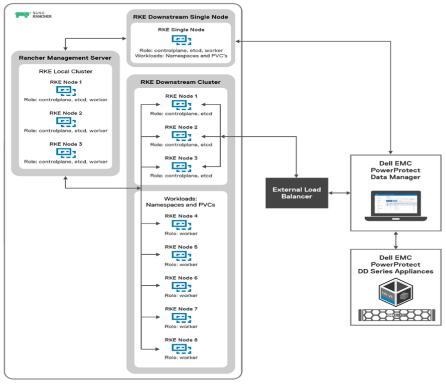
SUSE Rancher managed RKE downstream Kubernetes clusters integration with PowerProtect Data Manager
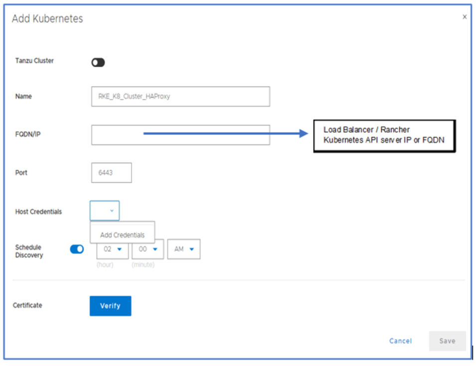
Adding the RKE downstream Kubernetes cluster with PowerProtect Data Manager as an asset source
Once the Kubernetes cluster is added as an asset source in PowerProtect Data Manager and the discovery is complete, the associated namespaces are available as assets for protection. PowerProtect Data Manager protects two types of Kubernetes cluster assets: Namespaces and PVCs. Note that PPDM also protects the associated metadata for namespaces and cluster resources that include secrets, ConfigMaps, custom resources, RoleBindings, and so on.
During the discovery process, PowerProtect Data Manager creates the following namespaces in the cluster:
- Velero-ppdm: This namespace contains a Velero pod to back up metadata and stage to target storage in bare-metal environments. It performs PVC snapshot and metadata backup for VMware cloud native storage.
- PowerProtect: This namespace contains a PowerProtect controller pod to drive persistent volume claim snapshot and backup, and to send the backups to the target storage using dynamically deployed cProxy pods.
Kubernetes uses persistent volumes to store persisted application data. Persistent volumes are created on external storage and then attached to a particular pod using PVCs. PVCs are included along with other namespaces in PowerProtect Data Manager backup and recovery operations. Dell EMC PowerStore, PowerMax, XtremIO, and PowerFlex storage platforms all come with CSI plugins to support containerized workloads running on Kubernetes.
With this easy integration for data protection with PowerProtect Data Manager, Dell Technologies empowers Kubernetes admins to perform backup/recovery operations and ensure that SUSE Rancher managed Kubernetes cluster workloads are available, consistent, durable, and recoverable.
For more details, see the white paper SUSE Rancher and RKE Kubernetes cluster using CSI Driver on DELL EMC PowerFlex about how to protect SUSE Rancher managed Kubernetes workloads with PowerProtect Data Manager.
Author: Vinod Kumaresan

Cloud DR - Deployments over a Private Network
Thu, 21 Jul 2022 16:21:20 -0000
|Read Time: 0 minutes
Dell EMC launched Cloud Disaster Recovery (Cloud DR) in 2017, to help customers expand their DR to the cloud and meet their compliance demands, and to give them peace of mind about running their workloads in the cloud in case of a disaster scenario.
The initial phase was to support the most used cloud platforms back then, AWS and Azure, and focus on simplicity and automation, all while leveraging existing data protection technologies that customers already have, such as Avamar and Data Domain.
From its first release, Cloud DR supported automated deployment. This process created everything the solution needed on the customer’s cloud account, and was initiated from the on-prem component (the Cloud DR Add-on (CDRA)) over the internet -- the most common way to connect small or medium size organizations to the cloud.
Over time, more and more organizations reached a level of maturity of cloud usage: in the way they worked with it, protected their resources running on the cloud, and in how they planned to combine that with their on-prem resources. All of this resulted in larger organizations requiring more advanced and up-to-date features that Cloud DR already offered.
To support those new and larger organizations, Cloud DR’s core functionality was integrated into additional data protection technologies, such as RecoverPoint for VMs, PowerProtect Data Manager, and PowerProtect DP (what used to be called IDPA), so organizations who were already working and using these solutions would also be able to benefit from Cloud DR features and to protect and recover their VMs to, and on, the cloud.
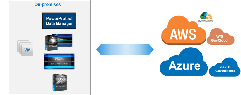
Naturally, larger organizations are more complex. They usually combine their cloud and on-prem resources, connecting the environments with VPN. Some also use a dedicated network (such as Direct Connect in AWS or ExpressRoute in Azure).
These customers wanted to leverage their private connections for the deployment and usage, but since Cloud DR's core ability was to deploy over the public internet and create its AWS or Azure resources with an auto generated public IP (because it was the original design that fit almost all of the customers, and because some customers had strict security rules preventing any public IP creation), there was naturally a rising demand to add support for VPN connections, without creating or using any public IP.
To address that concern, a solution was introduced for CDRA users to switch the way the CDRA communicates with the Cloud DR Server (CDRS), changing its default deployment from using a public IP to using its private IP, but this was relevant only for CDRA and only for specific Cloud DR releases (19.5 - 19.8).
In Cloud DR 19.9 (which is also included in PowerProtect Data Manager 19.9), released in September 2021, this requirement is further simplified. Cloud DR allows you to deploy over your existing private connection. In the web UI, you can also easily select whether you want to deploy through the internet and create a public IP, or deploy through your private network.
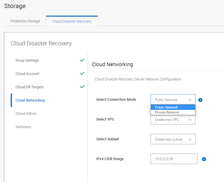
While the Cloud DR interface makes it easy and intuitive to select the connection mode, it’s important that you configure the networks properly to support private connectivity. (The most common cause for failed deployments is related to misconfigured networks, routing, and firewalls.)
This new feature should work as-is for well configured environments. You need to make sure your on-prem CDRA or PowerProtect Data Manager can reach and send its protected data to the cloud object storage (AWS S3 bucket / Azure Storage Account) over VPN. That’s because by default the object storage is reachable through the internet. Of course, you can also keep and use that default behavior and make sure that the CDRA or PowerProtect Data Manager can also send files through the internet, and connect to the CDRS through your VPN connection.
With Cloud DR and PowerProtect Data Manager you can protect your workloads with an easy deployment to your cloud account, and now also with a simplified deployment over your VPN.
Be sure to check out our Cloud DR best practices white paper, demos, and interactive demos:
Cloud DR Best practices whitepaper
Demos:
- PowerProtect Data Manager - Cloud DR Configuration and Deployment to AWS Demo
- PowerProtect Data Manager - Protection to the Cloud Demo
- PowerProtect Data Manager - Recovery from the Cloud Demo
- Cloud Disaster Recovery - Configuration and Deployment using CDRA to AWS Demo
- Cloud Disaster Recovery - Protection to the Cloud using Avamar Demo
- Cloud Disaster Recovery - Recovery Demo
Interactive Demos:
- Cloud DR with Avamar, RecoverPoint for VMs and PowerProtect DP
- Cloud DR with PowerProtect Data Manager
Author: Eli Persin

A Quick Update on how PowerProtect Data Manager Discovers Oracle Databases
Wed, 30 Nov 2022 23:09:59 -0000
|Read Time: 0 minutes
There’s a new Oracle database discovery method introduced in PowerProtect Data Manager version 19.9!
Dell EMC PowerProtect Data Manager provides software defined data protection, automated discovery, deduplication, operational agility, self-service, and IT governance for physical, virtual, and cloud environments. PowerProtect Data Manager helps you to:
- Orchestrate protection directly through an intuitive interface or empower data owners to perform self-service backup and restore operations from their native applications
- Enjoy unique VMware protection: Protect VMware VMs without business disruption
- Ensure compliance and meet even the strictest service level objectives
- Leverage your existing Dell EMC PowerProtect appliances
PowerProtect Data Manager gives you valuable insight into protected on-premises and in-cloud workloads, applications, file systems, and virtual machines. Designed with operational simplicity and agility in mind, PowerProtect Data Manager enables protecting traditional workloads, such as Oracle, Exchange, SQL, SAP HANA, and file systems, as well as Kubernetes containers and virtual environments.
PowerProtect Data Manager supports discovering Oracle databases through either the traditional /etc/oratab file located on the Oracle server or starting in PPDM 19.9, by using Oracle PMON (Process MONitor) processes. Let’s review these two methods.
Method 1:
PowerProtect Data Manager uses the /etc/oratab file to discover Oracle databases. Note that since the appearance of Oracle release 12.2, Oracle no longer updates the /etc/oratab file with information such as ORACLE_HOME and ORACLE_SID automatically. Administrators can still update the /etc/oratab file manually to continue using this discovery method.
Here’s an example of an /etc/oratab file with entries for a database called “oradb105”.
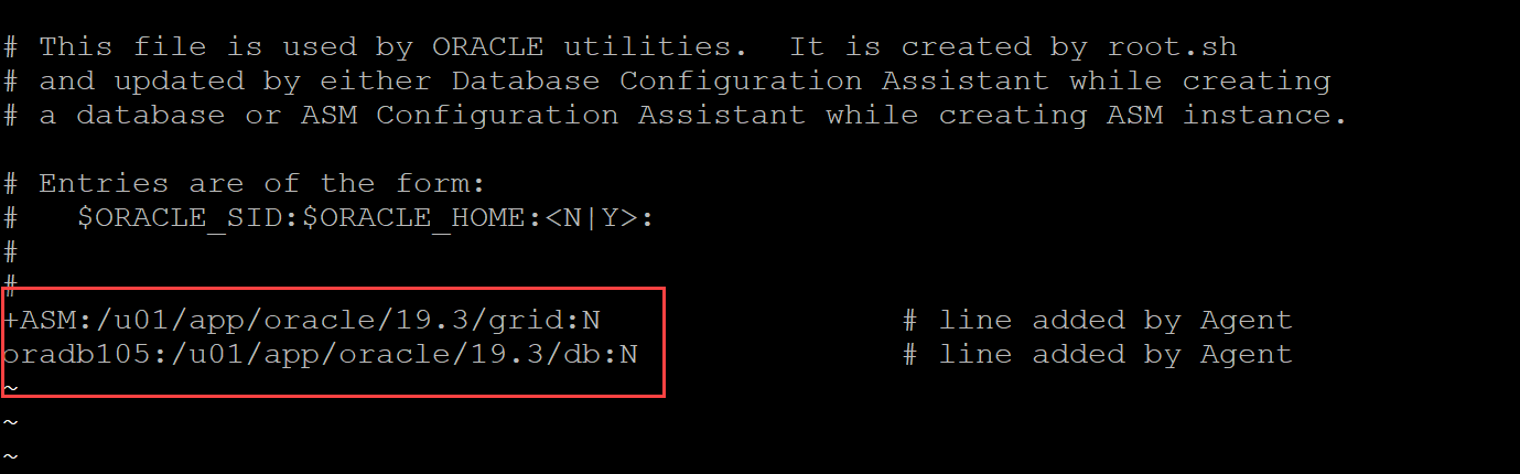
Method 2:
PowerProtect Data Manager 19.9 introduces a new mechanism for discovering Oracle databases. This method uses information contained in the Oracle PMON processes and doesn’t have dependencies on /etc/oratab entries. PMON is an Oracle background process created when a database instance is started.
Here’s an example of a PMON process for the same database mentioned earlier:
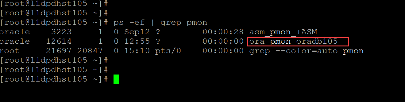
The PMON process contains the name of the database. The PowerProtect Data Manager discovery job will look for those PMON processes and add the database to the asset list (as in the following figure).
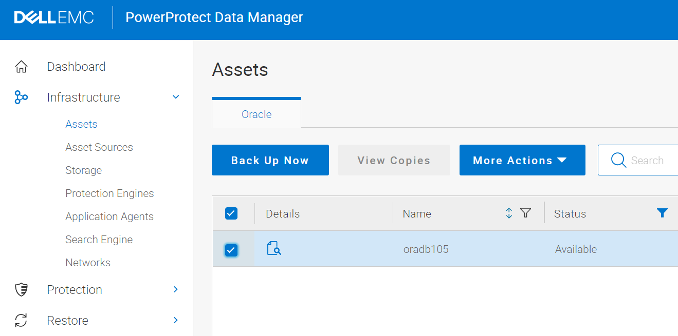
In conclusion, PowerProtect Data Manager no longer requires entries in the /etc/oratab to discover Oracle databases. Those entries will continue to have the highest precedence, but it will also look for Oracle PMON processes to gather the full list of assets.
I urge you to check out this interactive demo of PowerProtect Data Manager 19.9.
For more information, see the whitepaper PowerProtect Data Manager: Oracle® RMAN Agent Backup and Recovery that provides details about the Oracle RMAN agent architecture and the backup and restore workflow.
Author: Frank Gagnon